1991 ACURA NSX brake
[x] Cancel search: brakePage 1552 of 1640
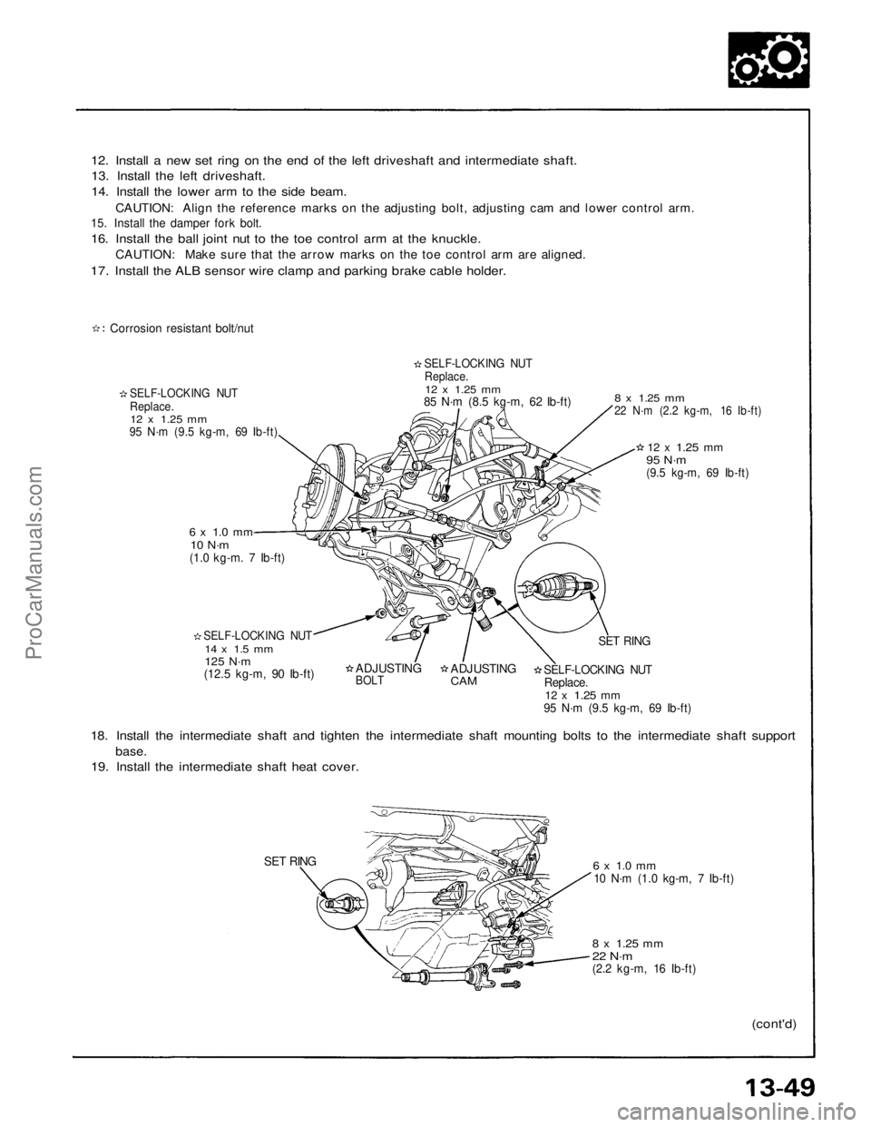
12. Install a new set ring on the end of the left driveshaft and intermediate shaft.
13. Install the left driveshaft.
14. Install the lower arm to the side beam.
CAUTION: Align the reference marks on the adjusting bolt, adjusting cam and lower control arm.
15. Install the damper fork bolt.
16. Install the ball joint nut to the toe control arm at the knuckle.
CAUTION: Make sure that the arrow marks on the toe control arm are aligned.
17. Install the ALB sensor wire clamp and parking brake cable holder.
Corrosion resistant bolt/nut
SELF-LOCKING NUT
Replace.
12 x
1.25
mm
95 N·m (9.5 kg-m, 69 Ib-ft)
SELF-LOCKING NUT
Replace.
12 x
1.25
mm
85 N·m (8.5 kg-m, 62 Ib-ft)
6 x 1.0 mm
10 N·m
(1.0 kg-m. 7 Ib-ft)
SELF-LOCKING NUT
14 x 1.5 mm
125 N·m
(12.5 kg-m, 90 Ib-ft)
8 x
1.25
mm
22 N·m (2.2 kg-m, 16 Ib-ft)
12 x
1.25
mm
95 N·m
(9.5 kg-m, 69 Ib-ft)
ADJUSTING
BOLT
ADJUSTING
CAM
SET RING
SELF-LOCKING NUT
Replace.
12 x
1.25
mm
95 N·m (9.5 kg-m, 69 Ib-ft)
18. Install the intermediate shaft and tighten the intermediate shaft mounting bolts to the intermediate shaft support
base.
19. Install the intermediate shaft heat cover.
SET RING
6 x 1.0 mm
10 N·m (1.0 kg-m, 7 Ib-ft)
8 x
1.25
mm
22 N·m
(2.2 kg-m, 16 Ib-ft)
(cont'd)ProCarManuals.com
Page 1553 of 1640
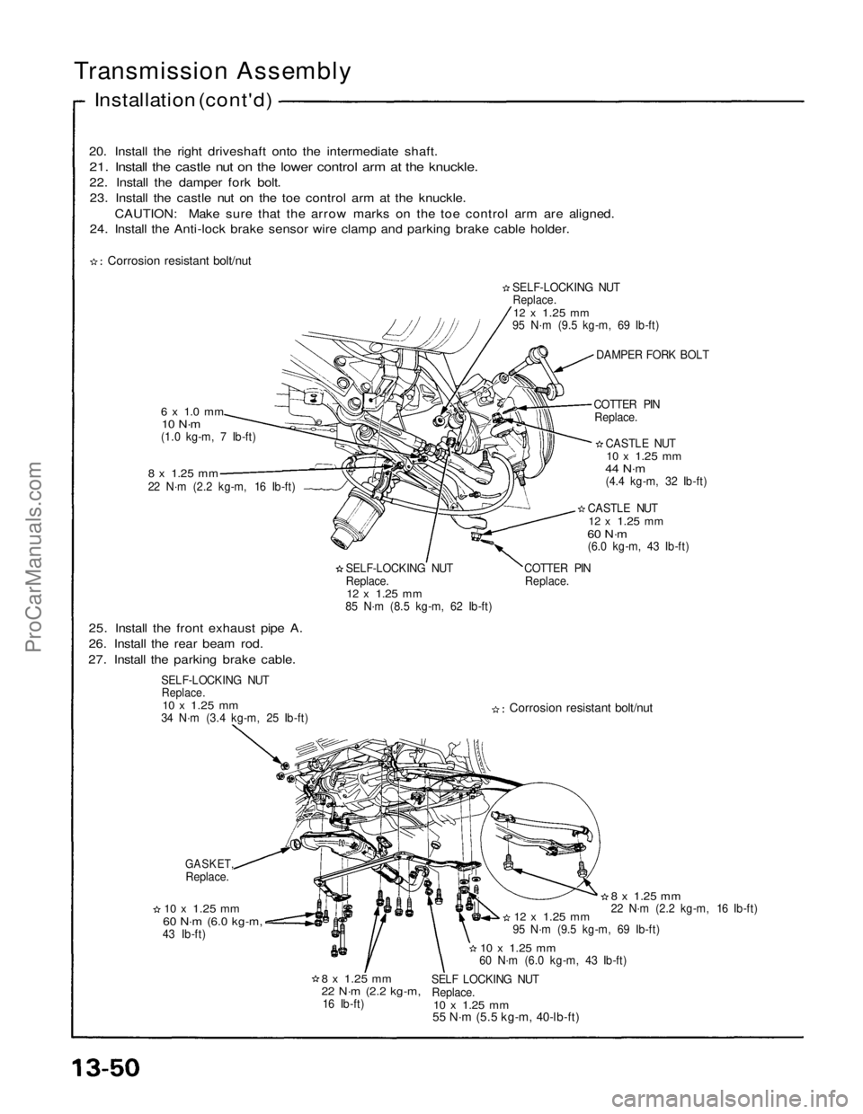
20. Install the right driveshaft onto the intermediate shaft.
21. Install the castle nut on the lower control arm at the knuckle.
22. Install the damper fork bolt.23. Install the castle nut on the toe control arm at the knuckle.
CAUTION: Make sure that the arrow marks on the toe control arm are aligned.
24. Install the Anti-lock brake sensor wire clamp and parking brake cable holder.
Transmission Assembly
Installation (cont'd)
Corrosion resistant bolt/nut
6 x 1.0 mm
10 N·m
(1.0 kg-m, 7 Ib-ft)
8 x
1.25
mm
22 N·m (2.2 kg-m, 16 Ib-ft)
SELF-LOCKING NUT
Replace.
12 x
1.25
mm
85 N·m (8.5 kg-m, 62 Ib-ft) COTTER PIN
Replace. CASTLE NUT
12 x
1.25
mm
60 N·m
(6.0 kg-m, 43 Ib-ft) CASTLE NUT
10 x
1.25
mm
44 N·m
(4.4 kg-m, 32 Ib-ft)
COTTER PIN
Replace. DAMPER FORK BOLT
SELF-LOCKING NUT
Replace.
12 x
1.25
mm
95 N·m (9.5 kg-m, 69 Ib-ft)
25. Install the front exhaust pipe A.
26. Install the rear beam rod.
27. Install the parking brake cable.
SELF-LOCKING NUT
Replace.
10 x
1.25
mm
34 N·m (3.4 kg-m, 25 Ib-ft)
Corrosion resistant bolt/nut
GASKET,
Replace.
10 x
1.25
mm
60 N·m
(6.0 kg-m,
43 Ib-ft)
8 x
1.25
mm
22 N·m
(2.2 kg-m,
16 Ib-ft) SELF LOCKING NUT
Replace.
10 x
1.25
mm
55 N·m (5.5 kg-m, 40-lb-ft)
10 x
1.25
mm
60 N·m (6.0 kg-m, 43 Ib-ft)
12 x
1.25
mm
95 N·m (9.5 kg-m, 69 Ib-ft)
8 x
1.25
mm
22 N·m (2.2 kg-m, 16 Ib-ft)ProCarManuals.com
Page 1569 of 1640
Troubleshooting
Anti-lock Brake System Indicator Light
Temporary Driving Conditions:
1. The anti-lock brake system indicator light will come
on and the control unit memorizes the problem
under certain conditions.
NOTE: Problem codes are explained on pages
19 - 46.
The tire(s) adhesion is lost due to excessive cor-
nering speed.
Problem codes: 5, 5-4, 5-8. The vehicle loses traction when starting from a
stuck condition on a muddy, snowy, or sandy
road.
Problem code: 4-1, 4-2, 4-4, 4-8. When the parking brake is applied for more than
30 seconds while the vehicle is being driven.
Problem code: 2. The vehicle is driven on extremely rough road.
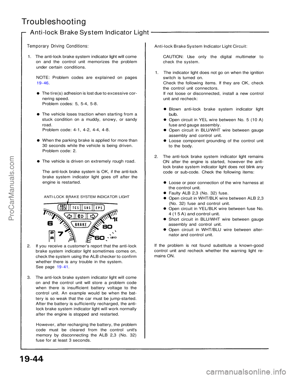
The anti-lock brake system is OK, if the anti-lock brake system indicator light goes off after the
engine is restarted.
ANTI-LOCK BRAKE SYSTEM INDICATOR LIGHT
2. If you receive a customer's report that the anti-lock brake system indicator light sometimes comes on,
check the system using the ALB checker to confirm
whether there is any trouble in the system.
See page 19 - 41.
3. The anti-lock brake system indicator light will come on and the control unit will store a problem codewhen there is insufficient battery voltage to the
control unit. An example would be when the bat-
tery is so weak that the car must be jump-started. After the battery is sufficiently recharged, the anti-lock brake system indicator light will work normally
after the engine is stopped and restarted.
However, after recharging the battery, the problem
code must be cleared from the control unit's
memory by disconnecting the ALB 2,3 (No. 32)
fuse for at least 3 seconds. Anti-lock Brake System Indicator Light Circuit:
CAUTION: Use only the digital multimeter to
check the system.
1. The indicator light does not go on when the ignition switch is turned on.
Check the following items. If they are OK, check
the control unit connectors. If not loose or disconnected, install a new control
unit and recheck:
Blown anti-lock brake system indicator light
bulb.
Open circuit in YEL wire between No. 5 (10 A)
fuse and gauge assembly. Open circuit in BLU/WHT wire between gauge
assembly and control unit. Loose component grounding of the control unit
to the body.
2. The anti-lock brake system indicator light remains ON after the engine is started, however the anti-lock brake system indicator light does not blink any
code or sub-code. Check the following items:
Loose or poor connection of the wire harness at
the control unit.
Faulty ALB 2,3 (No. 32) fuse.
Open circuit in WHT/BLK wire between ALB 2,3(No. 32) fuse and control unit.
Open circuit in YEL/BLK wire between fuse No.
4 (1 5 A) and control unit.
Short circuit in BLU/WHT wire between gauge
assembly and control unit. Open circuit in WHT/BLU wire between alter-
nator and control unit.
If the problem is not found substitute a known-good
control unit and recheck whether the warning light re-
mains ON.ProCarManuals.com
Page 1570 of 1640
Comes on and remains on while running:
1. Stop the engine.
2. Turn the ignition switch on and make sure that the anti-lock brake system indicator light comes on.
3. Restart the engine and check the anti-lock brake system indicator light.
There is no problem in the anti-lock brake system, if the anti-lock brake system indicator light goes off. Go to step 4, if the anti-lock brake system indicator light remains on.
4. Stop the engine.
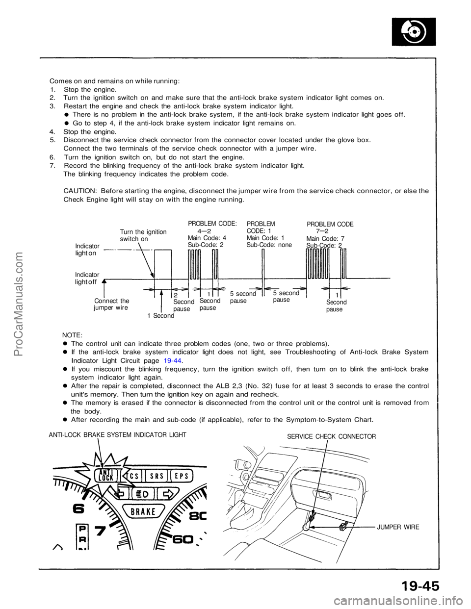
5. Disconnect the service check connector from the connector cover located under the glove box.
Connect the two terminals of the service check connector with a jumper wire.
6. Turn the ignition switch on, but do not start the engine. 7. Record the blinking frequency of the anti-lock brake system indicator light.
The blinking frequency indicates the problem code.
CAUTION: Before starting the engine, disconnect the jumper wire from the service check connector, or else the
Check Engine light will stay on with the engine running.
Turn the ignition
switch on
PROBLEM CODE:
4– 2
Main Code: 4
Sub-Code: 2
PROBLEM
CODE: 1
Main Code: 1
Sub-Code: none
PROBLEM CODE
7–2
Main Code: 7
Sub-Code: 2
Indicator
light on
Indicator
light off
Connect the
jumper wire
2
Second
pause
1
Second
pause
5 second
pause
5 second
pause
1
Second
pause
1 Second
NOTE:
The control unit can indicate three problem codes (one, two or three problems). If the anti-lock brake system indicator light does not light, see Troubleshooting of Anti-lock Brake System
Indicator Light Circuit page 19-44.
If you miscount the blinking frequency, turn the ignition switch off, then turn on to blink the anti-lock brake
system indicator light again. After the repair is completed, disconnect the ALB 2,3 (No. 32) fuse for at least 3 seconds to erase the control
unit's memory. Then turn the ignition key on again and recheck.
The memory is erased if the connector is disconnected from the control unit or the control unit is removed from
the body. After recording the main and sub-code (if applicable), refer to the Symptom-to-System Chart.
ANTI-LOCK BRAKE SYSTEM INDICATOR LIGHT
SERVICE CHECK CONNECTOR
JUMPER WIREProCarManuals.com
Page 1571 of 1640
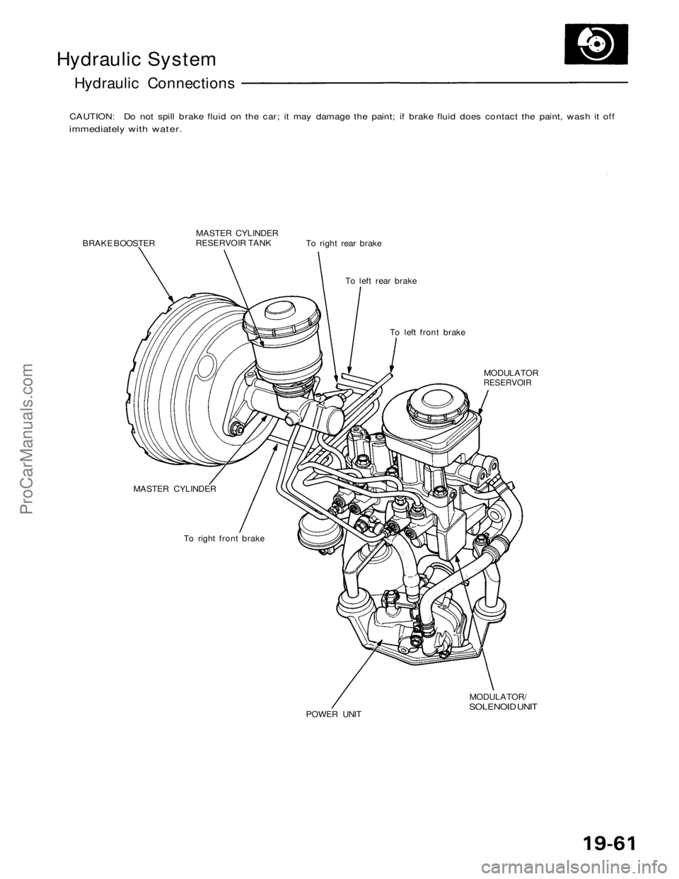
Hydraulic System
Hydraulic Connections
CAUTION: Do not spill brake fluid on the car; it may damage the paint; if brake fluid does contact the paint, wash it off
immediately with water.
BRAKE BOOSTER
MASTER CYLINDER
RESERVOIR TANK
To right rear brake
To left rear brake
To left front brake
MASTER CYLINDER
To right front brake
POWER UNIT
MODULATOR/
SOLENOID UNIT
MODULATOR
RESERVOIRProCarManuals.com
Page 1572 of 1640
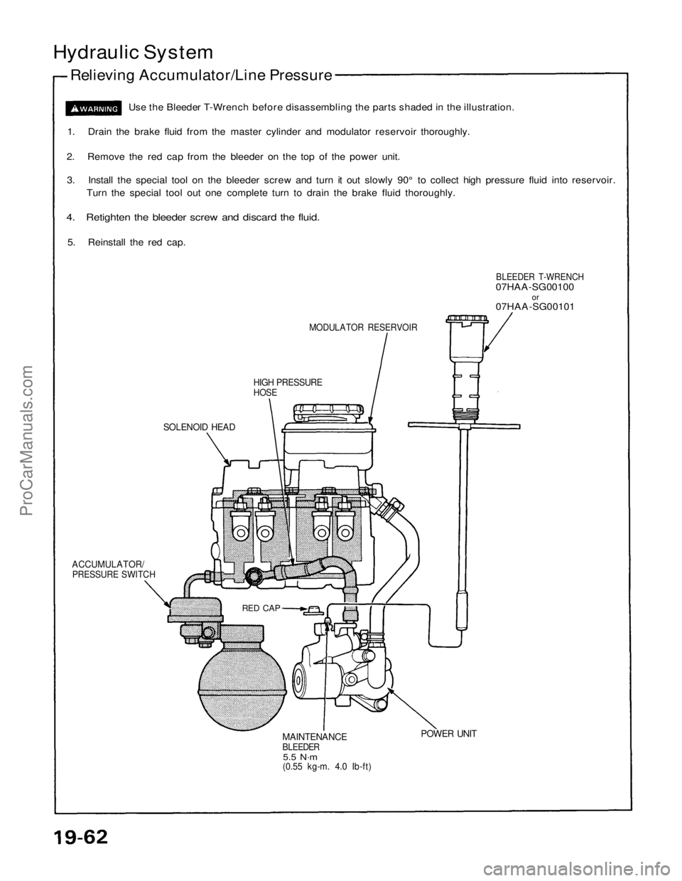
Hydraulic System
Relieving Accumulator/Line Pressure
Use the Bleeder T-Wrench before disassembling the parts shaded in the illustration.
1. Drain the brake fluid from the master cylinder and modulator reservoir thoroughly.
2. Remove the red cap from the bleeder on the top of the power unit.
3. Install the special tool on the bleeder screw and turn it out slowly 90° to collect high pressure fluid into reservoir.
Turn the special tool out one complete turn to drain the brake fluid thoroughly.
4. Retighten the bleeder screw and discard the fluid.
5. Reinstall the red cap.
MODULATOR RESERVOIR
HIGH PRESSURE
HOSE
BLEEDER T-WRENCH
07HAA-SG00100
or
07HAA-SG00101
SOLENOID HEAD
ACCUMULATOR/
PRESSURE SWITCH
RED CAP
MAINTENANCE
BLEEDER
5.5 N·m
(0.55 kg-m. 4.0 Ib-ft)
POWER UNITProCarManuals.com
Page 1573 of 1640
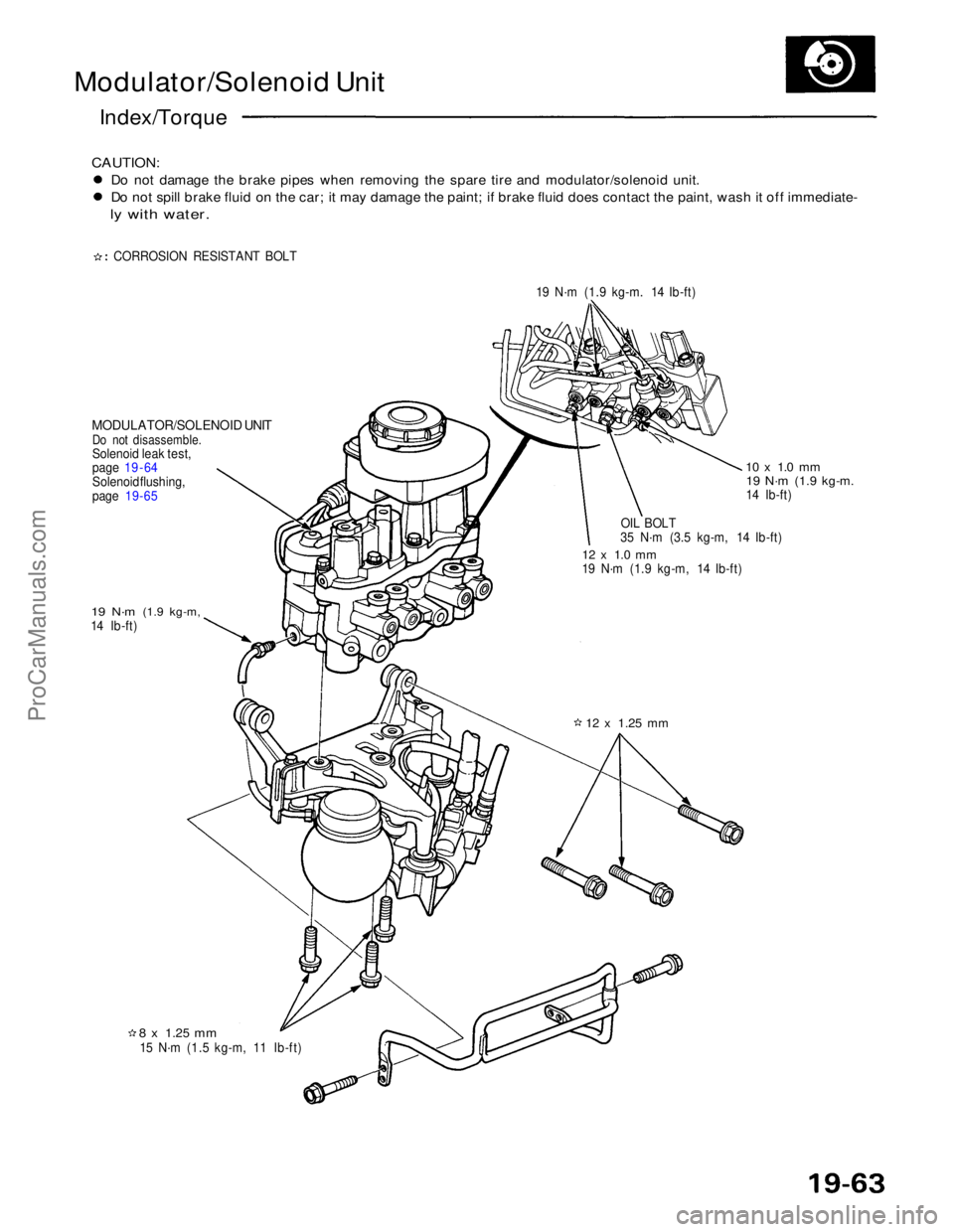
Modulator/Solenoid Unit
Index/Torque
CAUTION:
Do not damage the brake pipes when removing the spare tire and modulator/solenoid unit.
Do not spill brake fluid on the car; it may damage the paint; if brake fluid does contact the paint, wash it off immediate-
ly with water.
CORROSION RESISTANT BOLT 19 N·m (1.9 kg-m. 14 Ib-ft)
MODULATOR/SOLENOID UNIT
Do not disassemble.
Solenoid leak test,
page 19 - 64
Solenoid flushing,
page
19-65
19 N·m
(1.9 kg-m,
14 Ib-ft)
8 x
1.25
mm
15 N·m (1.5 kg-m, 11 Ib-ft)
12 x
1.25
mm
12 x 1.0 mm
19 N·m (1.9 kg-m, 14 Ib-ft)
OIL BOLT
35 N·m (3.5 kg-m, 14 Ib-ft)
10 x 1.0 mm
19 N·m
(1.9 kg-m.
14 Ib-ft)ProCarManuals.com
Page 1574 of 1640
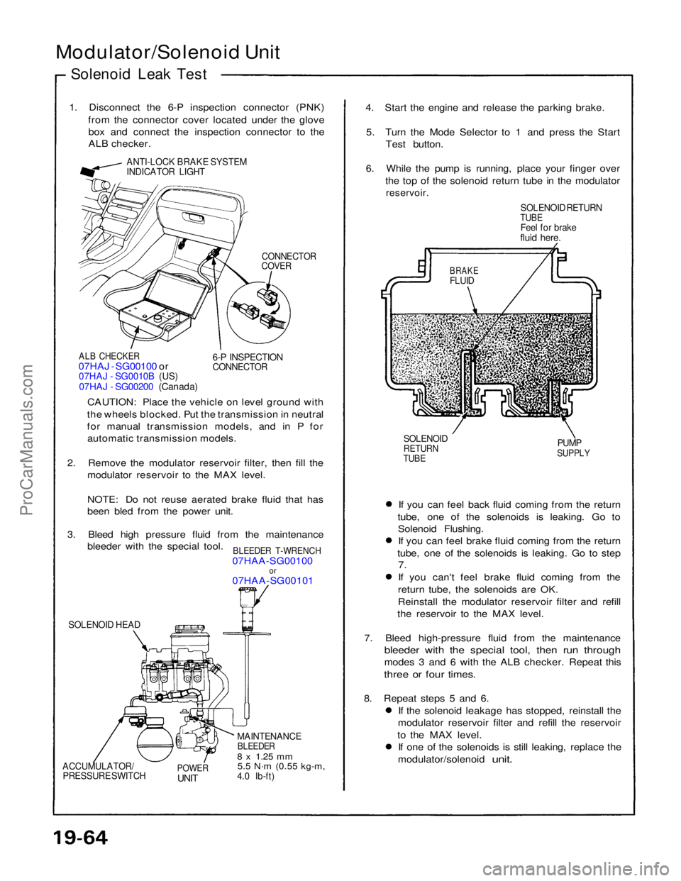
Modulator/Solenoid Unit
Solenoid Leak Test
1. Disconnect the 6-P inspection connector (PNK) from the connector cover located under the glovebox and connect the inspection connector to the
ALB checker.
ANTI-LOCK BRAKE SYSTEM
INDICATOR LIGHT
CONNECTOR
COVER
ALB CHECKER
07HAJ - SG00100 or
07HAJ - SG0010B (US)
07HAJ - SG00200 (Canada)
6-P INSPECTION
CONNECTOR
CAUTION: Place the vehicle on level ground with
the wheels blocked. Put the transmission in neutral
for manual transmission models, and in P for automatic transmission models.
2. Remove the modulator reservoir filter, then fill the modulator reservoir to the MAX level.
NOTE: Do not reuse aerated brake fluid that has
been bled from the power unit.
3. Bleed high pressure fluid from the maintenance bleeder with the special tool.
BLEEDER T-WRENCH
07HAA-SG00100
or
07HAA-SG00101
SOLENOID HEAD
MAINTENANCE
BLEEDER
8 x
1.25
mm
5.5 N·m
(0.55 kg-m,
4.0 Ib-ft)
POWER
UNIT
ACCUMULATOR/
PRESSURE SWITCH
If you can feel back fluid coming from the return
tube, one of the solenoids is leaking. Go to Solenoid Flushing.If you can feel brake fluid coming from the return
tube, one of the solenoids is leaking. Go to step
7.
If you can't feel brake fluid coming from the return tube, the solenoids are OK.
Reinstall the modulator reservoir filter and refill
the reservoir to the MAX level.
7. Bleed high-pressure fluid from the maintenance
bleeder with the special tool, then run through
modes 3 and 6 with the ALB checker. Repeat this
three or four times.
8. Repeat steps 5 and 6. If the solenoid leakage has stopped, reinstall the
modulator reservoir filter and refill the reservoir
to the MAX level. If one of the solenoids is still leaking, replace the
modulator/solenoid
unit.
SOLENOID
RETURN
TUBE
PUMP
SUPPLY
BRAKE
FLUID
SOLENOID RETURN
TUBE
Feel for brake
fluid here.
4. Start the engine and release the parking brake.
5. Turn the Mode Selector to 1 and press the Start Test button.
6. While the pump is running, place your finger over the top of the solenoid return tube in the modulator
reservoir.ProCarManuals.com