1991 ACURA NSX brake
[x] Cancel search: brakePage 524 of 1640
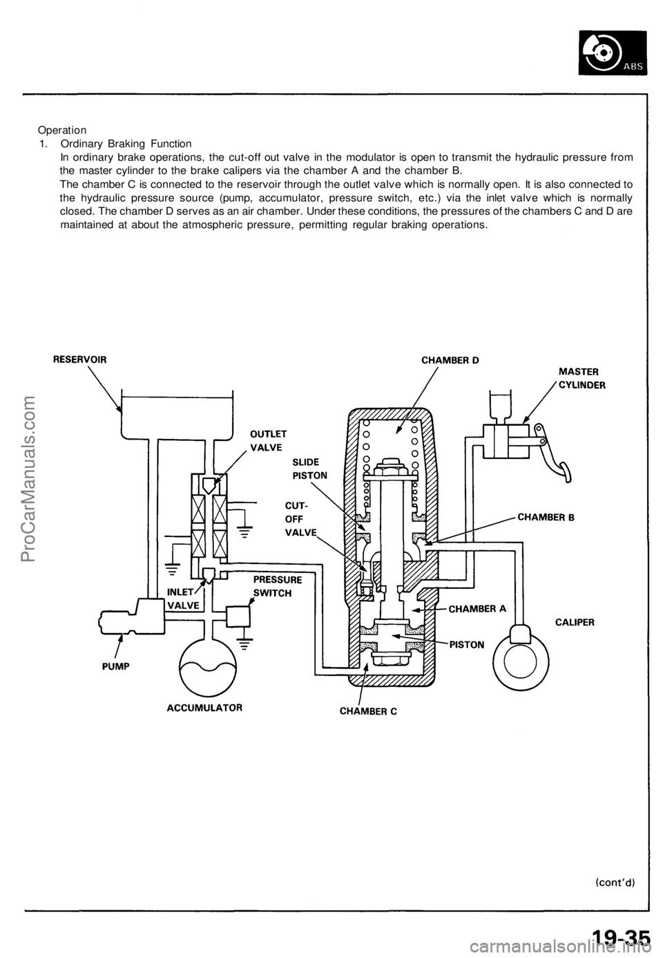
Operation
1. Ordinary Braking Function
In ordinary brake operations, the cut-off out valve in the modulator is open to transmit the hydraulic pressure from
the master cylinder to the brake calipers via the chamber A and the chamber B.
The chamber C is connected to the reservoir through the outlet valve which is normally open. It is also connected to
the hydraulic pressure source (pump, accumulator, pressure switch, etc.) via the inlet valve which is normally
closed. The chamber D serves as an air chamber. Under these conditions, the pressures of the chambers C and D are
maintained at about the atmospheric pressure, permitting regular braking operations.ProCarManuals.com
Page 527 of 1640
ALB Checke r
Function Tes t
NOTE :
• Th e AL B checke r i s designe d t o confir m prope r
operatio n of the anti-loc k brak e syste m (ABS ) b y
simulatin g eac h syste m functio n an d operatin g con -
dition . Befor e usin g th e checker , confir m tha t th e
anti-loc k brak e syste m (ABS ) indicato r ligh t i s no t in -
dicatin g som e othe r proble m wit h th e system . Th e
light shoul d g o o n whe n th e ignitio n i s firs t turne d o n
an d the n g o of f an d sta y of f on e secon d afte r th e
engin e i s started .
• Th e checke r shoul d b e use d throug h modes ,
1-5, t o
confir m prope r operatio n of the system , i n an y on e
of th e followin g situations :
Afte r replacin g an y AB S component .
Afte r replacin g o r bleedin g th e syste m flui d ( 0
mod e no t necessary) .
Afte r an y bod y o r suspensio n repai r tha t ma y
hav e affecte d th e sensor s o r thei r wiring .
• Th e procedur e fo r mode s
1-5 ar e o n thi s pag e an d
19-42 , mod e 0 (whee l senso r signal ) i s o n pag e
19-43 .
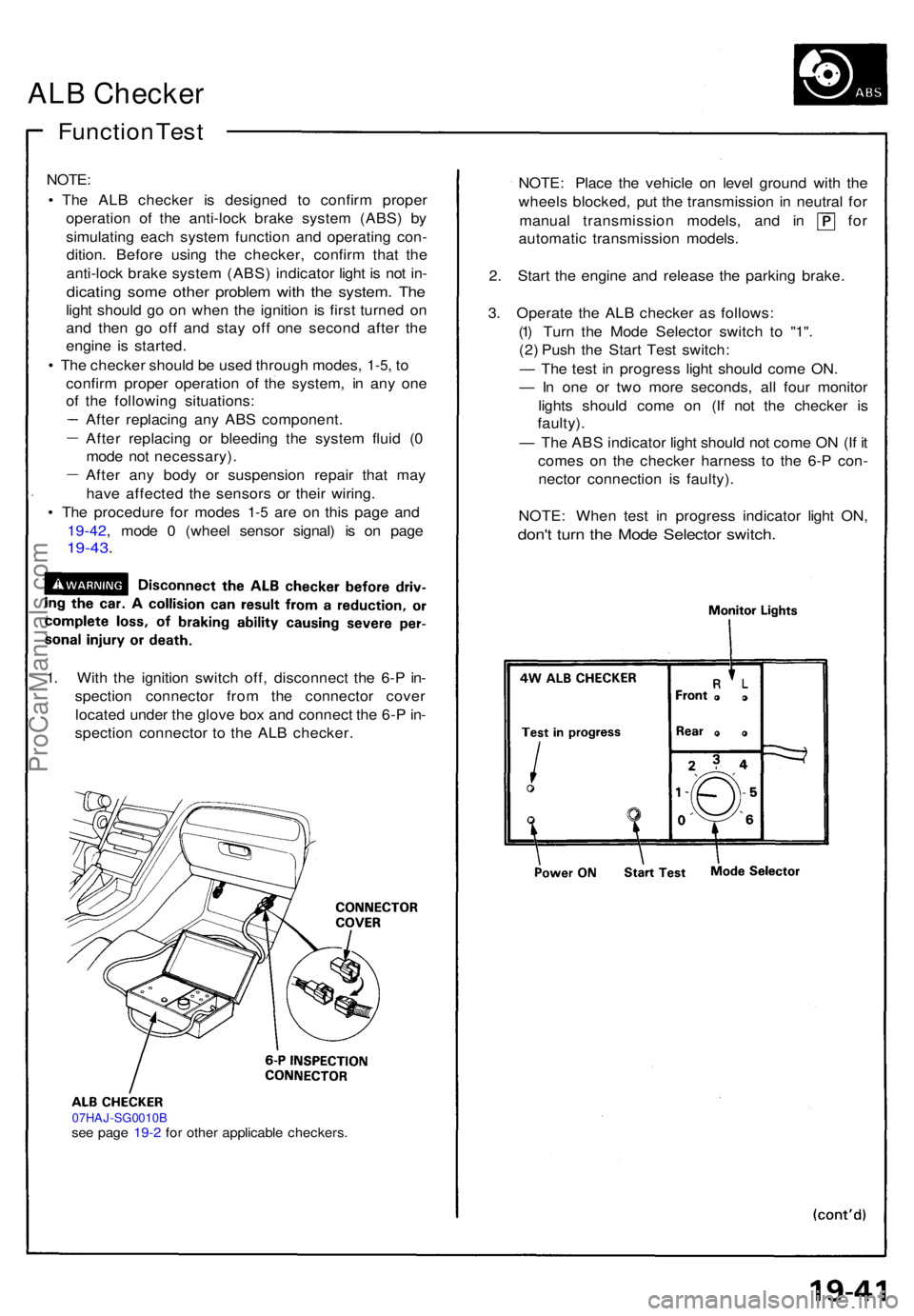
1. Wit h th e ignitio n switc h off , disconnec t th e 6- P in -
spectio n connecto r fro m th e connecto r cove r
locate d unde r th e glov e bo x an d connec t th e 6- P in -
spectio n connecto r t o th e AL B checker .
07HAJ-SG0010Bsee pag e 19- 2 fo r othe r applicabl e checkers .
NOTE: Plac e th e vehicl e o n leve l ground with th e
wheel s blocked , pu t th e transmissio n i n neutra l fo r
manua l transmissio n models , an d i n fo r
automati c transmissio n models .
2 . Star t th e engin e an d releas e th e parkin g brake .
3 . Operat e th e AL B checke r a s follows :
(1 ) Tur n th e Mod e Selecto r switc h t o "1" .
(2 ) Pus h th e Star t Tes t switch :
— Th e tes t i n progres s ligh t shoul d com e ON .
— In on e o r tw o mor e seconds , al l fou r monito r
light s shoul d com e o n (I f no t th e checke r i s
faulty) .
— Th e AB S indicato r ligh t shoul d no t com e O N (I f i t
come s o n th e checke r harnes s t o th e 6- P con -
necto r connectio n i s faulty) .
NOTE : Whe n tes t i n progres s indicato r ligh t ON ,
don't tur n th e Mod e Selecto r switch .
ProCarManuals.com
Page 528 of 1640
ALB Checker
Function Test (cont'd)
4. Turn the Mode Selector switch further to "2". 5. Depress the brake pedal firmly and push the Start
Test switch
The ABS indicator light should not go on while the
Test in Progress light is ON. There should bekickback on the brake pedal. If not as described, go
to troubleshooting, page 19-44 ('91-'92) ('93-'96).
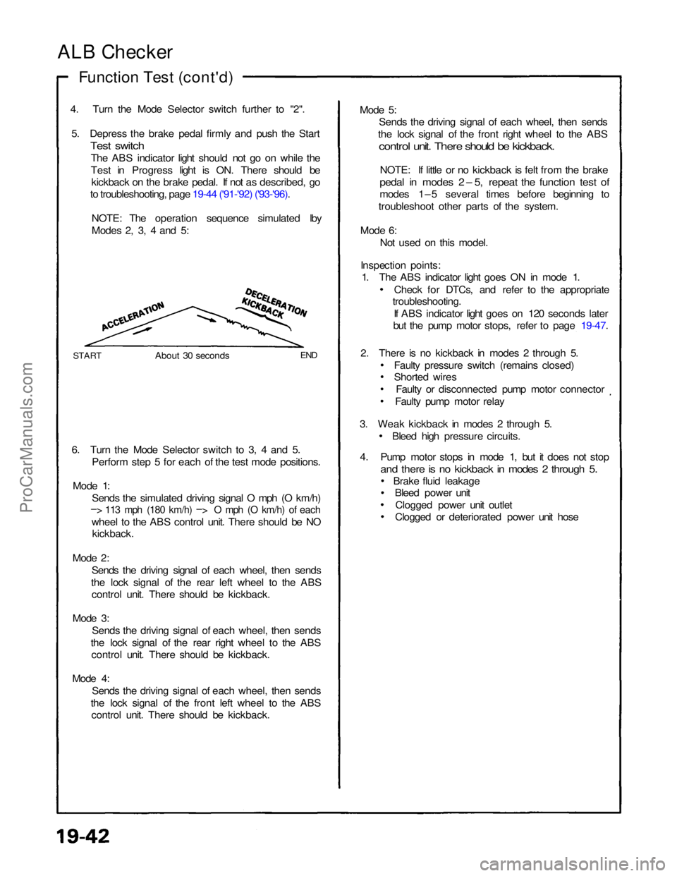
NOTE: The operation sequence simulated lby
Modes 2, 3, 4 and 5:
START
About 30 seconds
END
6. Turn the Mode Selector switch to 3, 4 and 5. Perform step 5 for each of the test mode positions.
Mode 1: Sends the simulated driving signal O mph (O km/h)
– > 113 mph (180 km/h) –
>
O mph (O km/h) of each
wheel to the ABS control unit. There should be NO
kickback.
Mode 2: Sends the driving signal of each wheel, then sends
the lock signal of the rear left wheel to the ABS control unit. There should be kickback.
Mode 3: Sends the driving signal of each wheel, then sends
the lock signal of the rear right wheel to the ABS control unit. There should be kickback.
Mode 4: Sends the driving signal of each wheel, then sends
the lock signal of the front left wheel to the ABS control unit. There should be kickback. Mode 5:
Sends the driving signal of each wheel, then sends
the lock signal of the front right wheel to the ABS
control unit. There should be kickback.
NOTE: If little or no kickback is felt from the brake
pedal in modes 2 – 5, repeat the function test of
modes 1–5 several times before beginning to
troubleshoot other parts of the system.
Mode 6: Not used on this model.
Inspection points: 1. The ABS indicator light goes ON in mode 1.
Check for DTCs, and refer to the appropriate
troubleshooting.
If ABS indicator light goes on 120 seconds later
but the pump motor stops, refer to page 19-47.
2. There is no kickback in modes 2 through 5. Faulty pressure switch (remains closed)
Shorted wiresFaulty or disconnected pump motor connector
Faulty pump motor relay
3. Weak kickback in modes 2 through 5. Bleed high pressure circuits.
4. Pump motor stops in mode 1, but it does not stop
and there is no kickback in modes 2 through 5.
Brake fluid leakageBleed power unit
Clogged power unit outlet
Clogged or deteriorated power unit hoseProCarManuals.com
Page 536 of 1640
Modulator/Solenoid Uni t
Solenoi d Lea k Tes t
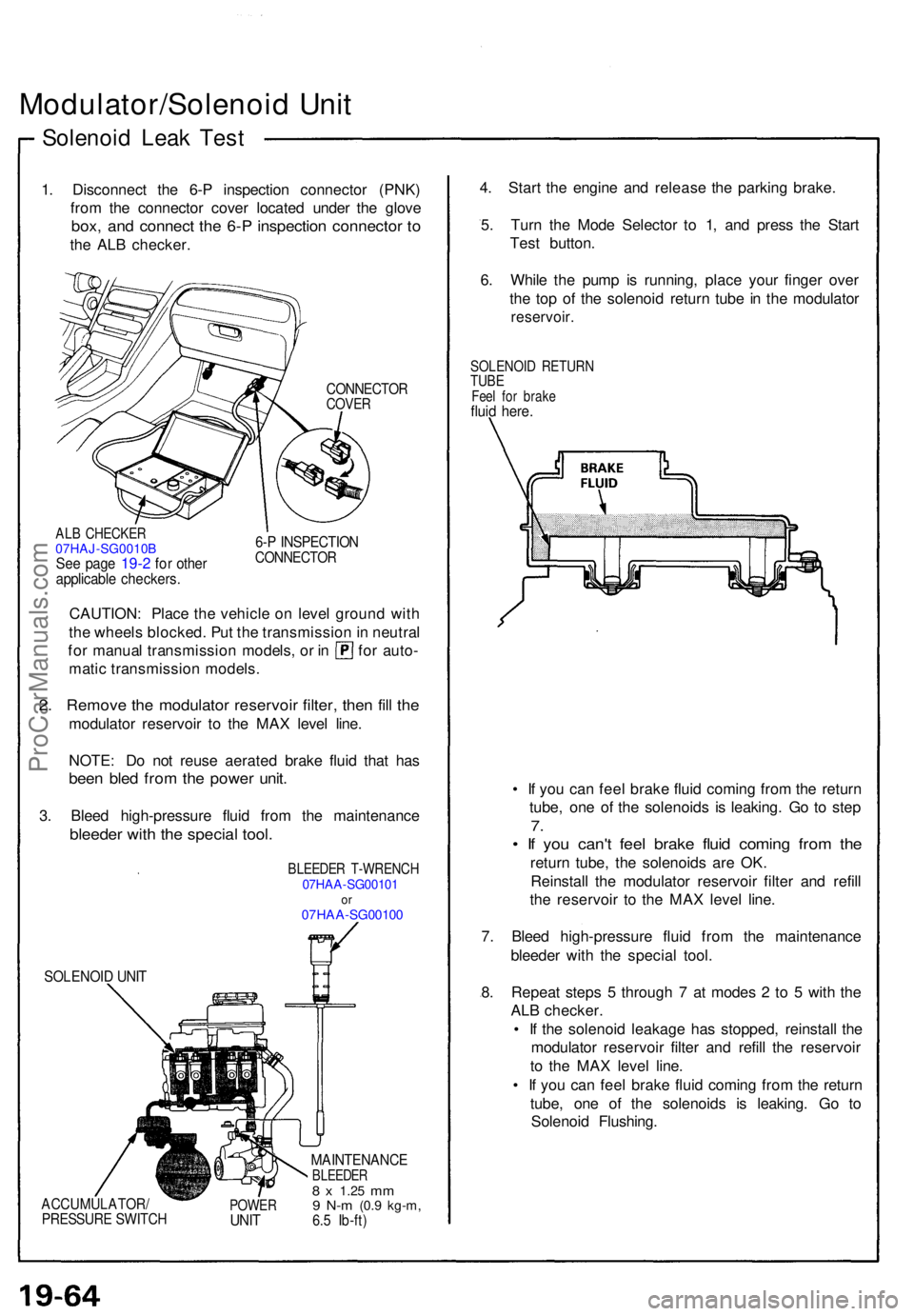
1. Disconnec t th e 6- P inspectio n connecto r (PNK )
fro m th e connecto r cove r locate d unde r th e glov e
box, an d connec t th e 6- P inspectio n connecto r t o
th e AL B checker .
CONNECTO RCOVER
ALB CHECKE R07HAJ-SG0010BSe e pag e 19-2 fo r othe rapplicabl e checkers .
6-P INSPECTIO NCONNECTO R
CAUTION: Plac e th e vehicl e o n leve l groun d wit h
th e wheel s blocked . Pu t th e transmissio n in neutra l
for manua l transmissio n models , o r i n fo r auto -
mati c transmissio n models .
2. Remov e th e modulato r reservoi r filter , the n fil l th e
modulato r reservoi r t o th e MA X leve l line .
NOTE : D o no t reus e aerate d brak e flui d tha t ha s
bee n ble d fro m th e powe r unit .
3. Blee d high-pressur e flui d fro m th e maintenanc e
bleeder with the specia l tool .
BLEEDE R T-WRENC H07HAA-SG0010 1or07HA A-SG0010 0
SOLENOI D UNI T
ACCUMULATOR /PRESSURE SWITC HPOWERUNIT
MAINTENANC EBLEEDER8 x 1.2 5 mm9 N- m (0. 9 kg-m ,6.5 Ib-ft )
4. Star t th e engin e an d releas e th e parkin g brake .
5 . Tur n th e Mod e Selecto r t o 1 , an d pres s th e Star t
Tes t button .
6 . Whil e th e pum p i s running , plac e you r finge r ove r
th e to p o f th e solenoi d retur n tub e in th e modulato r
reservoir.
SOLENOI D RETUR NTUBEFeel fo r brak efluid here .
• I f yo u ca n fee l brak e flui d comin g fro m th e retur n
tube , on e o f th e solenoid s i s leaking . G o t o ste p
7.
• I f yo u can' t fee l brak e flui d comin g fro m th e
retur n tube , th e solenoid s ar e OK .
Reinstal l th e modulato r reservoi r filte r an d refil l
th e reservoi r t o th e MA X leve l line .
7 . Blee d high-pressur e flui d fro m th e maintenanc e
bleede r wit h th e specia l tool .
8 . Repea t step s 5 throug h 7 at mode s 2 to 5 wit h th e
AL B checker .
• I f th e solenoi d leakag e ha s stopped , reinstal l th e
modulato r reservoi r filte r an d refil l th e reservoi r
t o th e MA X leve l line .
• I f yo u ca n fee l brak e flui d comin g fro m th e retur n
tube , on e o f th e solenoid s i s leaking . G o t o
Solenoi d Flushing .
ProCarManuals.com
Page 537 of 1640
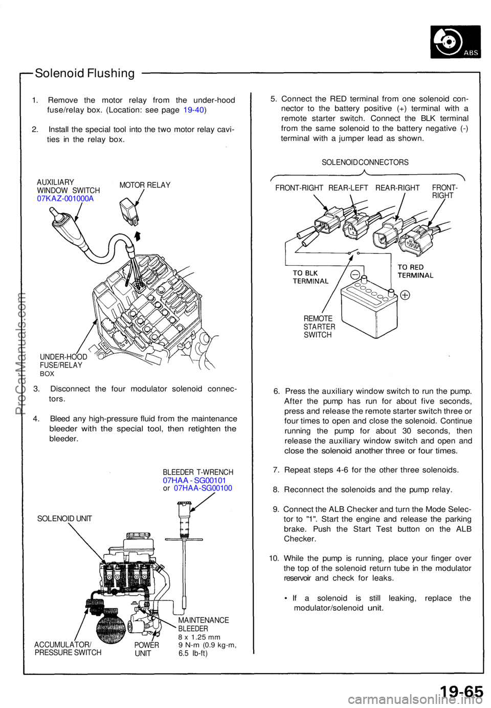
Solenoid Flushin g
1. Remov e th e moto r rela y fro m th e under-hoo d
fuse/rela y box . (Location : se e pag e 19-40 )
2 . Instal l th e specia l too l int o th e tw o moto r rela y cavi -
tie s i n th e rela y box .
AUXILIAR Y
WINDO W SWITC H
07KAZ-001000 A
MOTOR RELA Y
UNDER-HOO DFUSE/RELAYBOX
3. Disconnec t th e fou r modulato r solenoi d connec -
tors .
4 . Blee d an y high-pressur e flui d fro m th e maintenanc e
bleeder wit h th e specia l tool , the n retighte n th e
bleeder .
SOLENOI D UNI T
BLEEDE R T-WRENC H07HAA - SG0010 1or 07HA A-SG0010 0
ACCUMULATOR /
PRESSUR E SWITC HPOWERUNIT
MAINTENANC EBLEEDER8 x 1.2 5 mm9 N- m (0. 9 kg-m ,6.5 Ib-ft )
5. Connec t th e RE D termina l fro m on e solenoi d con -
necto r t o th e batter y positiv e (+ ) termina l wit h a
remot e starte r switch . Connec t th e BL K termina l
fro m th e sam e solenoi d t o th e batter y negativ e (- )
termina l wit h a jumpe r lea d a s shown .
SOLENOI D CONNECTOR S
FRONT-RIGH T REAR-LEF T REAR-RIGH T
FRONT-RIGHT
REMOT ESTARTE RSWITCH
6. Pres s th e auxiliar y windo w switc h t o ru n th e pump .
Afte r th e pum p ha s ru n fo r abou t fiv e seconds ,
pres s an d releas e th e remot e starte r switc h thre e o r
fou r time s t o ope n an d clos e th e solenoid . Continu e
runnin g th e pum p fo r abou t 3 0 seconds , the n
releas e th e auxiliar y windo w switc h an d ope n an d
clos e th e solenoi d anothe r thre e o r fou r times .
7. Repea t step s 4- 6 fo r th e othe r thre e solenoids .
8 . Reconnec t th e solenoid s an d th e pum p relay .
9 . Connec t th e AL B Checke r an d tur n th e Mod e Selec -
to r t o "1" . Star t th e engin e an d releas e th e parkin g
brake . Pus h th e Star t Tes t butto n o n th e AL B
Checker .
10. Whil e th e pum p i s running , plac e you r finge r ove r
th e to p o f th e solenoi d retur n tub e in th e modulato r
reservoi r an d chec k fo r leaks .
• I f a solenoi d i s stil l leaking , replac e th e
modulator/solenoi d
unit.
ProCarManuals.com
Page 539 of 1640
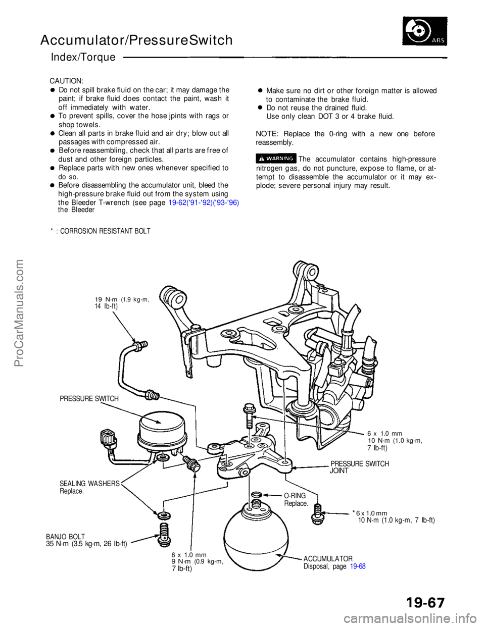
Accumulator/Pressure Switch
Index/Torque
CAUTION: Do not spill brake fluid on the car; it may damage the
paint; if brake fluid does contact the paint, wash it
off immediately with water.
To prevent spills, cover the hose jpints with rags or shop towels.
Clean all parts in brake fluid and air dry; blow out all passages with compressed air.
Before reassembling, check that all parts are free of
dust and other foreign particles. Replace parts with new ones whenever specified to
do so.
Before disassembling the accumulator unit, bleed the
high-pressure brake fluid out from the system using
the Bleeder T-wrench (see page 19-62('91-'92)('93-'96)
the Bleeder
*: CORROSION RESISTANT BOLT
Make sure no dirt or other foreign matter is allowed
to contaminate the brake fluid. Do not reuse the drained fluid.
Use only clean DOT 3 or 4 brake fluid.
NOTE: Replace the 0-ring with a new one before
reassembly. The accumulator contains high-pressure
nitrogen gas, do not puncture, expose to flame, or at-
tempt to disassemble the accumulator or it may ex-
plode; severe personal injury may result.
19 N·m
(1.9 kg-m,
14 Ib-ft)
PRESSURE SWITCH
SEALING WASHERS
Replace.
BANJO BOLT
35 N·m (3.5 kg-m, 26 Ib-ft)
6 x 1.0 mm
9 N·m
(0.9 kg-m,7 Ib-ft)
ACCUMULATOR
Disposal, page 19-68
* 6 x 1.0 mm
10 N·m (1.0 kg-m, 7 Ib-ft)
O-RING
Replace.
PRESSURE SWITCH
JOINT
6 x 1.0 mm
10 N·m
(1.0 kg-m,
7 Ib-ft)ProCarManuals.com
Page 541 of 1640
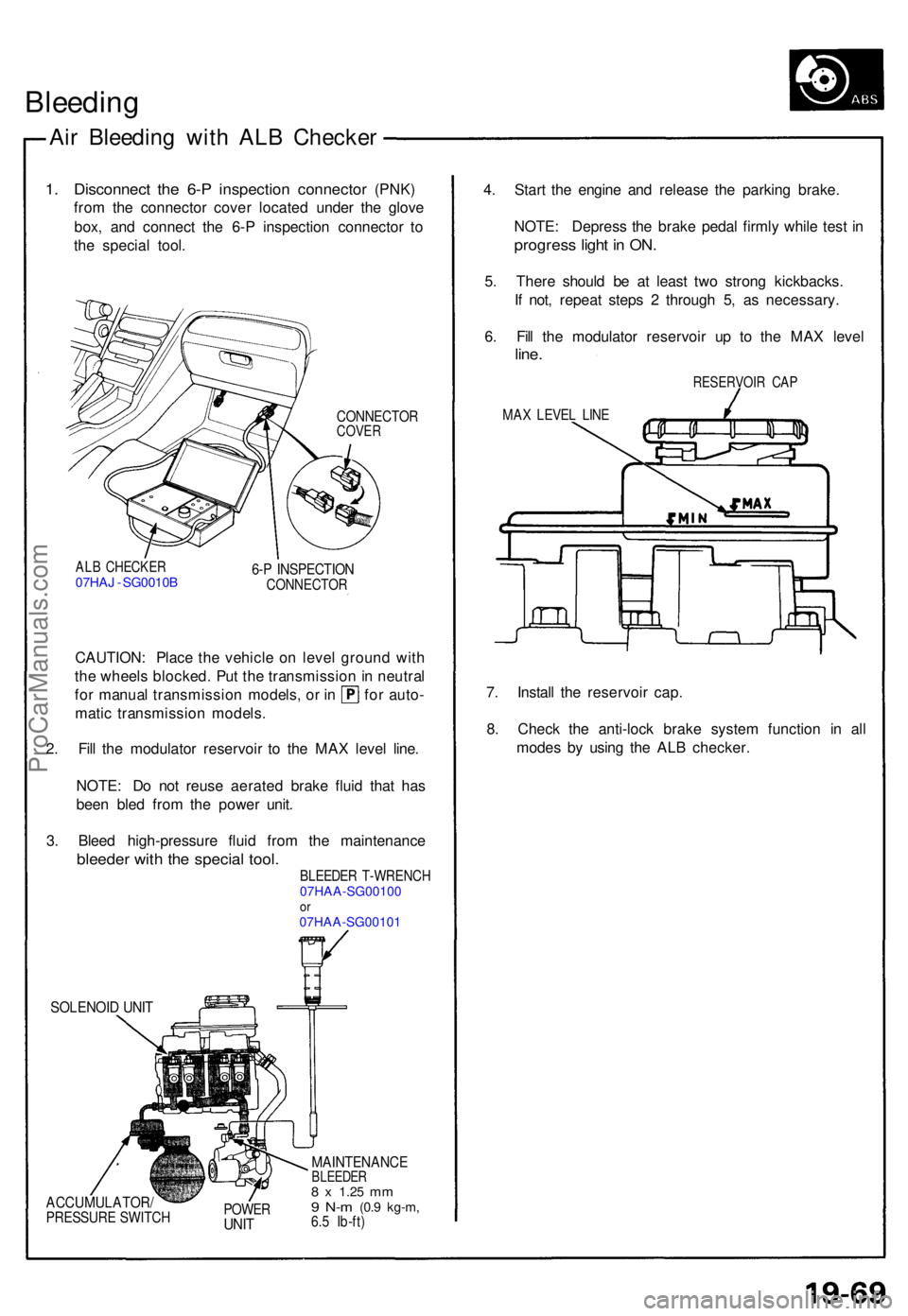
Bleeding
Air Bleedin g wit h AL B Checke r
1. Disconnec t the 6- P inspection connector (PNK )
fro m th e connecto r cove r locate d unde r th e glov e
box , an d connec t th e 6- P inspectio n connecto r t o
th e specia l tool .
CONNECTO RCOVER
ALB CHECKE R07HAJ - SG0010 B 6-P INSPECTIO NCONNECTO R
CAUTION: Plac e th e vehicl e o n leve l groun d wit h
th e wheel s blocked . Pu t th e transmissio n in neutra l
for manua l transmissio n models , o r i n fo r auto -
mati c transmissio n models .
2 . Fil l th e modulato r reservoi r t o th e MA X leve l line .
NOTE : D o no t reus e aerate d brak e flui d tha t ha s
bee n ble d fro m th e powe r unit .
3 . Blee d high-pressur e flui d fro m th e maintenanc e
bleeder wit h th e specia l tool.BLEEDE R T-WRENC H07HAA-SG00100or07HAA-SG00101
SOLENOI D UNI T
ACCUMULATOR /PRESSURE SWITC HPOWERUNIT
MAINTENANC EBLEEDER8 x 1.2 5 mm9 N- m (0. 9 kg-m ,6.5 Ib-ft )
4. Star t th e engin e an d releas e th e parkin g brake .
NOTE : Depres s th e brak e peda l firml y whil e tes t i n
progres s ligh t i n ON .
5. Ther e shoul d b e a t leas t tw o stron g kickbacks .
I f not , repea t step s 2 throug h 5 , a s necessary .
6 . Fil l th e modulato r reservoi r u p t o th e MA X leve l
line.
RESERVOI R CA P
MAX LEVE L LIN E
7. Instal l th e reservoi r cap .
8 . Chec k th e anti-loc k brak e syste m functio n i n al l
mode s b y usin g th e AL B checker .
ProCarManuals.com
Page 609 of 1640
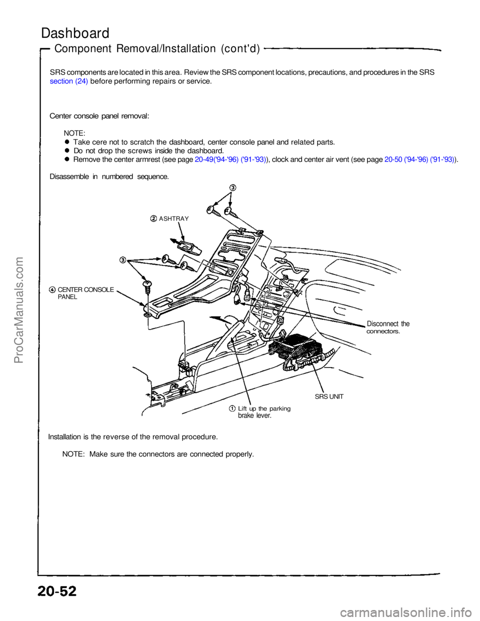
Dashboard
Component Removal/Installation (cont'd)
SRS components are located in this area. Review the SRS component locations, precautions, and procedures in the SRS
section (24) before performing repairs or service.
Center console panel removal:
NOTE:
Take cere not to scratch the dashboard, center console panel and related parts.Do not drop the screws inside the dashboard.
Remove the center armrest (see page 20-49('94-'96) ('91-'93)), clock and center air vent (see page 20-50 ('94-'96) ('91-'93)).
Disassemble in numbered sequence.
ASHTRAY
CENTER CONSOLE
PANEL
Disconnect the
connectors.
Lift up the parking
brake lever.
SRS UNIT
Installation is the reverse of the removal procedure. NOTE: Make sure the connectors are connected properly.ProCarManuals.com