Page 860 of 1640

(G551) '95-'96 Models.
(G401,G402,G551) '93-94 Models or
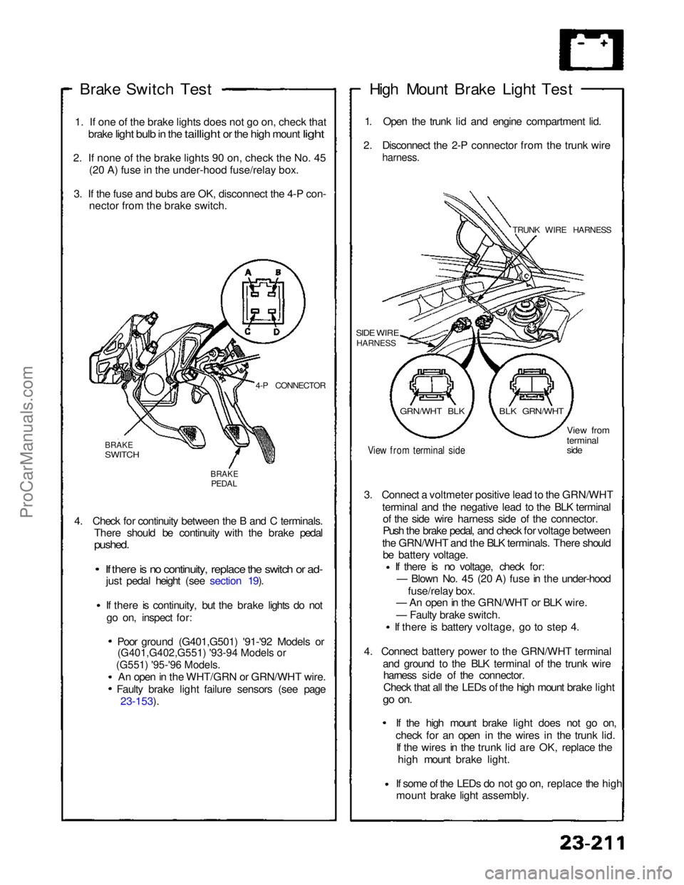
Brake Switch
Test
1
.
If one of the brake lights does not go on, check that
brake
light bulb in the taillight or the high mount light
2
.
If none of the brake lights 90 on, check the No. 45 (2
0
A) fuse in the under-hood fuse/relay box.
3
.
If the fuse and bubs are OK, disconnect the 4-P con- necto
r
from the brake switch.
4-P CONNECTOR
BRAKE
SWITCH
BRAKE
PEDAL
4. Check for continuity between the B and C terminals. There should be continuity with the brake pedal
pushed.
If there is no continuity, replace the switch or ad-
just pedal height (see section 19).
If there is continuity, but the brake lights do not
go on, inspect for:
Poor ground (G401,G501) '91-'92 Models or
An open in the WHT/GRN or GRN/WHT wire. Faulty brake light failure sensors (see page 23-153). High Mount Brake Light Test
1. Open the trunk lid and engine compartment lid.
2. Disconnect the 2-P connector from the trunk wire
harness.
TRUNK WIRE HARNESS
SIDE WIRE
HARNESS
View from terminal side
View from
terminal
side
3. Connect a voltmeter positive lead to the GRN/WHT terminal and the negative lead to the BLK terminalof the side wire harness side of the connector.
Push the brake pedal, and check for voltage between
the GRN/WHT and the BLK terminals. There should be battery voltage. If there is no voltage, check for:
— Blown No. 45 (20 A) fuse in the under-hood
fuse/relay box.
— An open in the GRN/WHT or BLK wire.
— Faulty brake switch.
If there is battery voltage, go to step 4.
4. Connect battery power to the GRN/WHT terminal and ground to the BLK terminal of the trunk wireharness side of the connector.
Check that all the LEDs of the high mount brake light
go on.
If the high mount brake light does not go on,check for an open in the wires
in the trunk lid.
If the wires in the trunk lid are OK, replace the
high mount brake light.
If some of the LEDs do not go on,
replace the high
mount brake light assembly.
GRN/WHT BLK
BLK GRN/WHTProCarManuals.com
Page 861 of 1640
Brake Lights
High Mount Brake Light Replacement
CAUTION: Be careful not to damage the high mount
brake light, rear spoiler, and trunk lid.
1. Open the trunk lid.
2. Remove the caps and five screws from the rear
spoiler.
REAR
SPOILER
SCREW
CAP
3. Carefully pull the high mount brake light out of the
rear spoiler, then disconnect the 2-P connector from
the high mount brake light.
REAR SPOILER
2-P CONNECTOR
HIGH MOUNT BRAKE LIGHT
(LED)
Rear Spoiler Replacement
CAUTION: Be careful not to damage the high mount
brake light, rear spoiler, and trunk lid.
1. Open the trunk lid.
2. Remove the six mounting nuts.
REAR
SPOILER
3.
Carefully
lift
the
rear
spoiler assembly
off the
rear
trunk lid.
REAR SPOILER
2-P CONNECTOR (Trunk sub-harness side)
4. Disconnect the 2-P connector from the trunk sub-
harness.ProCarManuals.com
Page 933 of 1640
Cruise Control
Component Location Index
SRS components are located in this area. Review the
SRS component locations, precautions, and procedures
in the SRS section (24) before performing repairs or ser-
vice.
BRAKE SWITCH
Test, page 23-308 ('93-'96) ('91-'92) INDICATOR LIGHT and
DIMMIN
G
CIRCUIT
(In tha gauge assembly)
Bulb Locations, page 23-128
('94-'96) ('91-'93)
MAIN SWITCH
Test, page 23-306 Replacement, page 23-305
SET/RESUME SWITCH
Test, page 23-307 ('93-'96) ('91-'92)
Replacement, page 23-307('93-'96) ('91-'92)
A/T GEAR POSITION
SWITCH
Test, 23-309 ('93-'96) ('91-'92) Replacement, page 23-161 ('93-'96) ('91-'92)
CABLE REEL
Test, page 23-250
Replacement, see section 24
CLUTCH SWITCH (M/T)
Test, page 23-308 ('93-'96) ('91-'92)ProCarManuals.com
Page 935 of 1640

Cruise Control
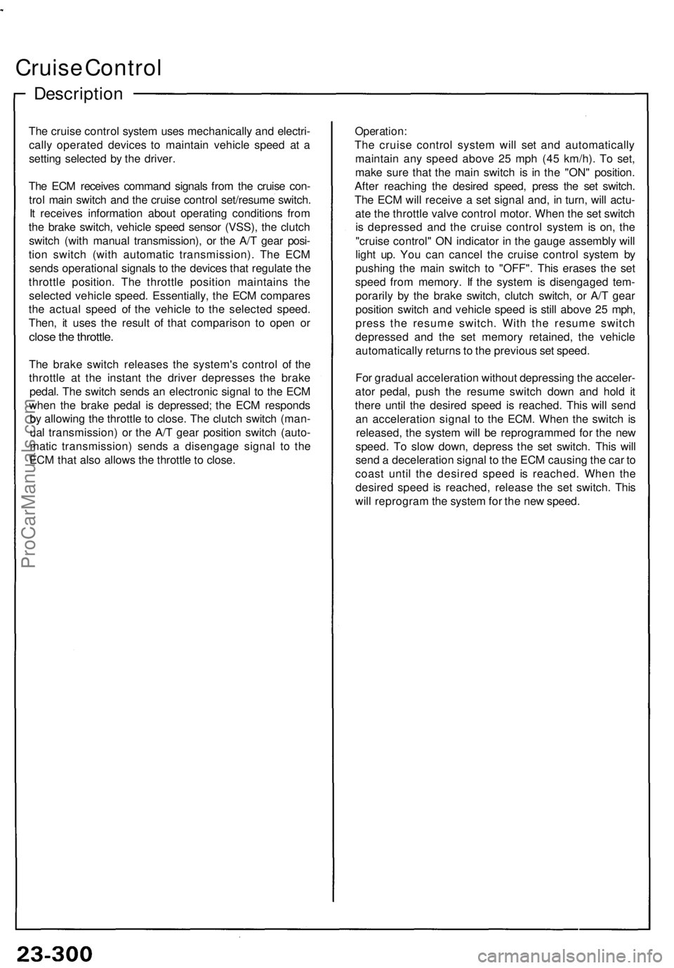
Description
The cruise control system uses mechanically and electri-
cally operated devices to maintain vehicle speed at a
setting selected by the driver.
The ECM receives command signals from the cruise con-
trol main switch and the cruise control set/resume switch.
It receives information about operating conditions from
the brake switch, vehicle speed sensor (VSS), the clutch
switch (with manual transmission), or the A/T gear posi-
tion switch (with automatic transmission). The ECM
sends operational signals to the devices that regulate the
throttle position. The throttle position maintains the
selected vehicle speed. Essentially, the ECM compares
the actual speed of the vehicle to the selected speed.
Then, it uses the result of that comparison to open or
close the throttle.
The brake switch releases the system's control of the
throttle at the instant the driver depresses the brake
pedal. The switch sends an electronic signal to the ECM
when the brake pedal is depressed; the ECM responds
by allowing the throttle to close. The clutch switch (man-
ual transmission) or the A/T gear position switch (auto-
matic transmission) sends a disengage signal to the
ECM that also allows the throttle to close.
Operation:
The cruise control system will set and automatically
maintain any speed above 25 mph (45 km/h). To set,
make sure that the main switch is in the "ON" position.
After reaching the desired speed, press the set switch.
The ECM will receive a set signal and, in turn, will actu-
ate the throttle valve control motor. When the set switch
is depressed and the cruise control system is on, the
"cruise control" ON indicator in the gauge assembly will
light up. You can cancel the cruise control system by
pushing the main switch to "OFF". This erases the set
speed from memory. If the system is disengaged tem-
porarily by the brake switch, clutch switch, or A/T gear
position switch and vehicle speed is still above 25 mph,
press the resume switch. With the resume switch
depressed and the set memory retained, the vehicle
automatically returns to the previous set speed.
For gradual acceleration without depressing the acceler-
ator pedal, push the resume switch down and hold it
there until the desired speed is reached. This will send
an acceleration signal to the ECM. When the switch is
released, the system will be reprogrammed for the new
speed. To slow down, depress the set switch. This will
send a deceleration signal to the ECM causing the car to
coast until the desired speed is reached. When the
desired speed is reached, release the set switch. This
will reprogram the system for the new speed.ProCarManuals.com
Page 943 of 1640
Cruise Contro l
Brake Switc h Tes t
1. Disconnec t th e 4- P connecto r fro m th e switch .
BRAKESWITC H
4-P CONNECTO R
BRAKEPEDAL
2. Chec k fo r continuit y betwee n th e terminal s accor -
din g t o th e table .
3 . I f necessary , replac e th e switc h o r adjus t peda l
heigh t (se e sectio n 19 ).
Clutc h Switc h Tes t
1. Disconnec t th e 3- P connecto r fro m th e switch .
CLUTCH
SWITC H 3- P CONNECTO R
CLUTC H BRAK E PEDA L
PEDAL
2. Chec k fo r continuit y betwee n th e terminal s accor -
din g t o th e table.
3 . I f necessary , replac e th e switc h o r adjus t peda l
height (se e sectio n 12 ).
ProCarManuals.com
Page 960 of 1640
Warning/Caution Label Locations
SRS CAUTION LABELS: Refer to page 1-8.
FROZEN
BATTERY CAUTION
BATTERY
CAUTION
RADIATOR BLEED
PLUG CAUTION
AIR CONDITIONING
R-134a CAUTION (U.S.A only)
EXPANSION
TANK CAP
CAUTION
ENGINE COOLANT CAUTION PRECAUTION
SPARK PLUG
CAUTION
TIRE INFORMATION
ABS CAUTION
ABS and BRAKE
FLUID CAUTION
RETRACTABLE
HEADLIGHT CAUTION
EMISSION CONTROL
INFORMATION and
VACUUM HOSE
ROUTING DIAGRAM
(cont'd)ProCarManuals.com
Page 965 of 1640

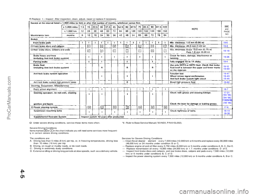
R-Replace I — Inspect After inspection, clean, adjust, repair or replace if necessary.
sec
and
PAGE
NO
19-6 19-8
19-18
19-26
19-4
19-10
19-69
19-41
19-43 19-44
19-62
18-7
17-21
('93-'96)
('94-'96)
17-60('94-'96)
('94-'96)
17-6
18-14
18-30
Under severe driving conditions, service these items more often.
Severe Driving Conditions
Items marked or in the chart indicate you will need some services more frequent-
ly in certain severe driving conditions.
The conditions are:
A: Driving loss than 5 miles (8 km) per trip, or, in freezing temperatures, driving less than 10 miles (16 km) per trip.
B: Driving, on rough or muddy roads, or de-iced roads.
C: Driving in extremely dusty conditions.
D: Extensive idling or driving long periods at slow speeds, such as a delivery vehicle. *6 : Ruler to Base Service Manual ('93 NSX, P/N 61SL002).
Services for Severe Driving Conditions
—
Clean
the air
cleaner
element
every
7,500 miles
(12,000
kml or 6
months
and
replace every
30,000
miles (48,000 km) or 24 months under condition B or C,
— Replace engine oil and oil filter every 3,750 miles (6,000 km) or\
3 months under conditions A, B, C, Dor E.
— Replace transmission oil every 15,000 miles (24,000 km) or 1 7. months under conditions D of E.
— Inspect front brake discs and calipers, and rear brake dises, calipers and pads every 7,500 miles (12,000
km) or 6 months under conditions B, C of D.
— Inspect the power steering system every 7,500 miles (12,000 km) or 6 months under conditions A, B or C.ProCarManuals.com
Page 969 of 1640
Warning/Caution Label Locations
SRS CAUTION LABELS: Refer to page 1-8.
FROZEN
BATTERY CAUTION
BATTERY
CAUTION
RADIATOR BLEED
PLUG CAUTION
AIR CONDITIONING R-134a CAUTION(U.S.A only)
EXPANSION
TANK CAP CAUTION
ENGINE COOLANT
CAUTION • PRECAUTION
SPARK PLUG
CAUTION
TIRE INFORMATION
EMISSION CONTROL
INFORMATION and
VACUUM HOSE
ROUTING DIAGRAM
RETRACTABLE
HEADLIGHT CAUTION
ABS and BRAKE
FLUID CAUTION ABS CAUTION
(cont'd)ProCarManuals.com