Page 245 of 1640

Idle Contro l Syste m
Brake Switc h Signa l
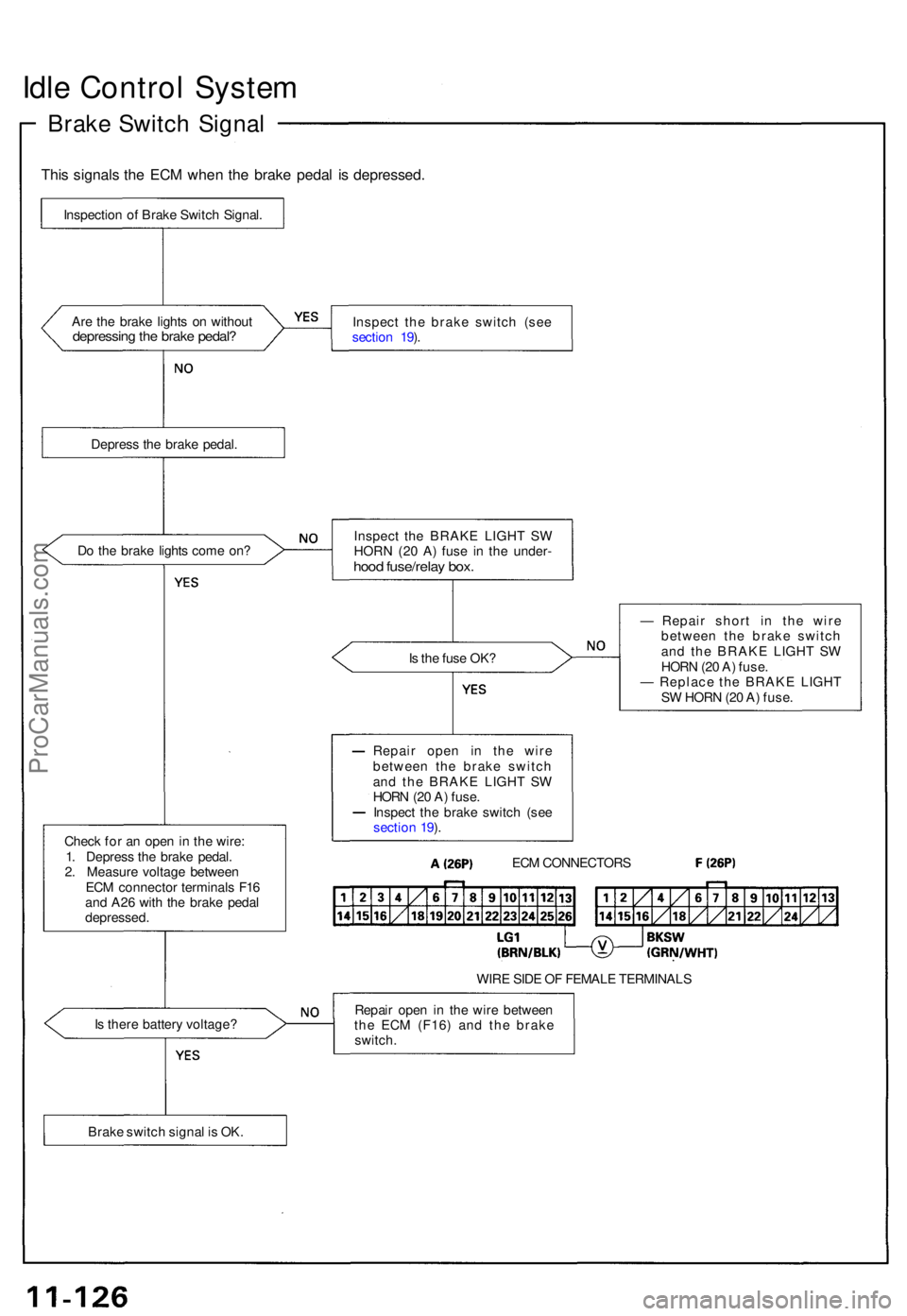
This signal s th e EC M whe n th e brak e peda l i s depressed .
Are th e brak e light s o n withou tdepressin g th e brak e pedal ?Inspec t th e brak e switc h (se e
sectio n 19 ).
Depres s th e brak e pedal .
D o th e brak e light s com e on ?
Is th e fus e OK ?
Chec k fo r a n ope n in th e wire :
1 . Depres s th e brak e pedal .
2 . Measur e voltag e betwee n
EC M connecto r terminal s F1 6
an d A2 6 wit h th e brak e peda l
depressed . —
Repai r shor t i n th e wir e
betwee n th e brak e switc h
an d th e BRAK E LIGH T S W
HOR N (2 0 A ) fuse .
— Replac e th e BRAK E LIGH T
S W HOR N (2 0 A ) fuse .
WIR E SID E O F FEMAL E TERMINAL S
I s ther e batter y voltage ? Repai
r ope n i n th e wir e betwee n
th e EC M (F16 ) an d th e brak e
switch .
Inspectio
n o f Brak e Switc h Signal .
Inspect th e BRAK E LIGH T S W
HORN (20 A ) fus e i n th e under -
hood fuse/rela y box .
Repai r ope n i n th e wir e
betwee n th e brak e switc h
an d th e BRAK E LIGH T S W
HOR N (2 0 A ) fuse .
Inspec t th e brak e switc h (se e
sectio n 19 ).
ECM CONNECTOR S
Brak e switc h signa l i s OK .
ProCarManuals.com
Page 286 of 1640

Slave Cylinde r
Remova l
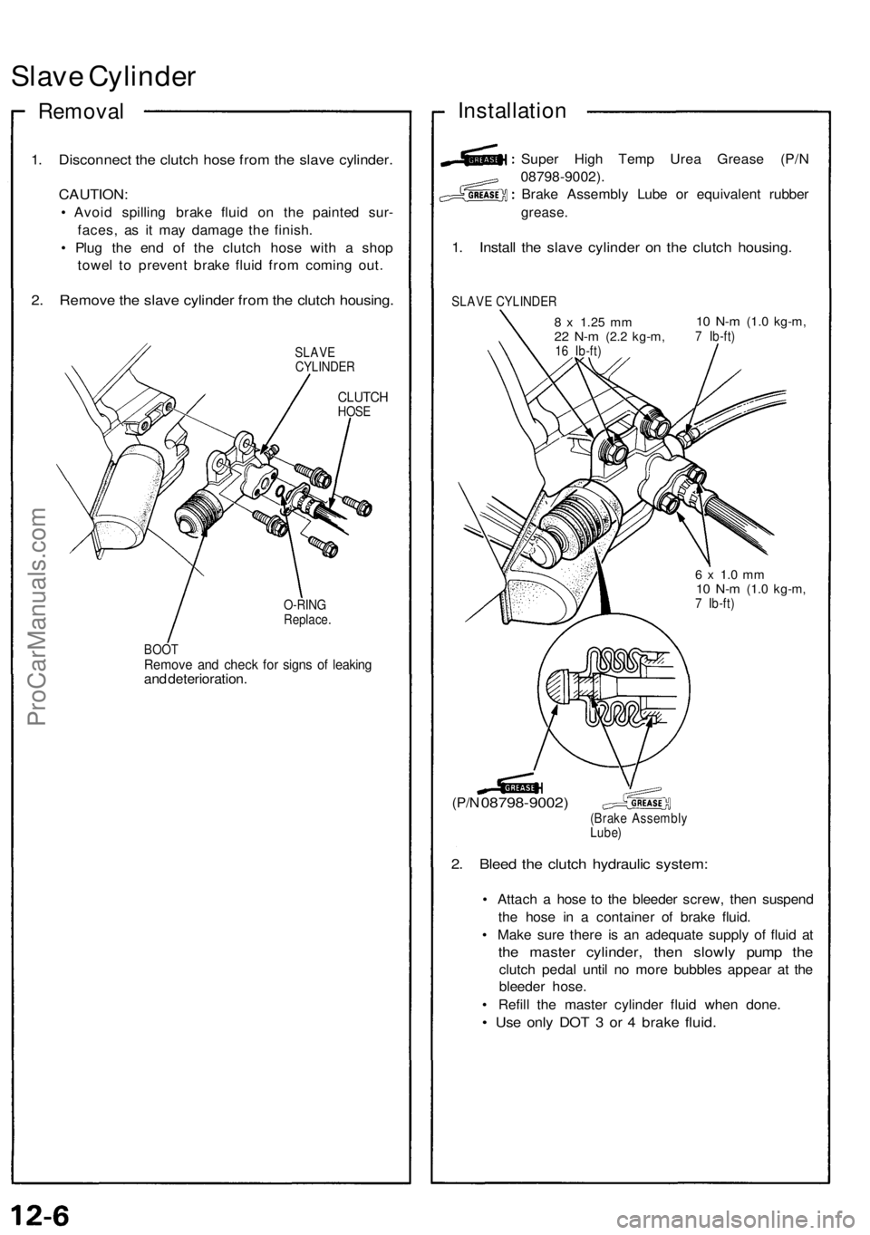
1. Disconnec t th e clutc h hos e fro m th e slav e cylinder .
CAUTION :
• Avoi d spillin g brak e flui d o n th e painte d sur -
faces , a s i t ma y damag e th e finish .
• Plu g th e en d o f th e clutc h hos e wit h a sho p
towe l t o preven t brak e flui d fro m comin g out .
2. Remov e th e slav e cylinde r fro m th e clutc h housing .
SLAVE
CYLINDE R
CLUTCHHOSE
O-RIN G
Replace .
BOO T
Remov e an d chec k fo r sign s o f leakin gand deterioration .
Installation
Super Hig h Tem p Ure a Greas e (P/ N
08798-9002) .
Brake Assembl y Lub e o r equivalen t rubbe r
grease .
1. Instal l th e slav e cylinde r o n th e clutc h housing .
SLAVE CYLINDE R
8 x 1.2 5 mm22 N- m (2. 2 kg-m ,16 Ib-ft )
10 N- m (1. 0 kg-m ,7 Ib-ft )
(P/N 08798-9002 )(Brake Assembl y
Lube )
2. Blee d th e clutc h hydrauli c system :
• Attac h a hos e t o th e bleede r screw , the n suspen d
th e hos e i n a containe r o f brak e fluid .
• Mak e sur e ther e i s a n adequat e suppl y of flui d a t
the maste r cylinder , the n slowl y pum p th e
clutc h peda l unti l n o mor e bubble s appea r a t th e
bleede r hose .
• Refil l th e maste r cylinde r flui d whe n done .
• Us e onl y DO T 3 or 4 brak e fluid .
6 x 1. 0 m m10 N- m (1. 0 kg-m ,7 Ib-ft )
ProCarManuals.com
Page 288 of 1640
Slave Cylinder (Canada)
Overhaul/Inspection
Super High Temp
Urea
Grease
(P/N
08798-9002).
Brake Assembly Lube or equivalent rubber grease.
SLAVE CYLINDER SPRING
Install with small end
facing piston.
(Brake Assembly
Lube)
SLAVE CYLINDER BODY
Inspect the cylinder wall for
scoring and wear.
(Brake Assembly
Lube)
BLEEDER SCREW
10 N-m (1.0 kg-m, 7 Ib-ft)
SLAVE CYLINDER PISTON
Inspect for wear and damage.
(P/N 08798-9002)
(Brake Assembly
Lube)
BOOT
Check that it is fitted securely
over cylinder body.
PUSH ROD
PISTON CUP B
Replace.
PISTON CUP A
Replace.ProCarManuals.com
Page 306 of 1640

Transmission Assembly
Removal
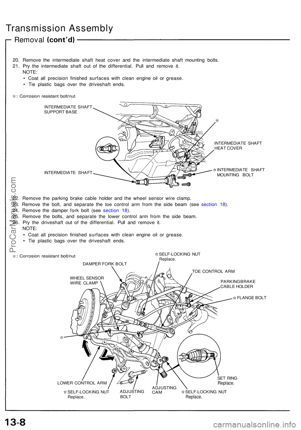
20. Remove the intermediate shaft heat cover and the intermediate shaft mounting bolts.
21. Pry the intermediate shaft out of the differential. Pull and remove it. NOTE:
• Coat all precision finished surfaces with clean engine oil or grease.
• Tie plastic bags over the driveshaft ends.
Corrosion resistant bolt/nut
INTERMEDIATE SHAFT
SUPPORT BASE
INTERMEDIATE SHAFT INTERMEDIATE SHAFT
HEAT COVER
INTERMEDIATE SHAFT
MOUNTING BOLT
22. Remove the parking brake cable holder and the wheel sensor wire clamp.
23. Remove the bolt, and separate the toe control arm from the side beam (see section 18).
24. Remove the damper fork bolt (see section 18).
25. Remove the bolts, and separate the lower control arm from the side beam. 26. Pry the driveshaft out of the differential. Pull and remove it. NOTE:
• Coat all precision finished surfaces with clean engine oil or grease.
• Tie plastic bags over the driveshaft ends.
Corrosion resistant bolt/nut
DAMPER FORK BOLT SELF-LOCKING NUT
Replace.
TOE CONTROL ARM
WHEEL SENSOR WIRE CLAMP PARKING BRAKE
CABLE HOLDER
FLANGE BOLT
LOWER CONTROL ARM SELF-LOCKING NUTReplace. ADJUSTING
BOLT
ADJUSTING
CAM
SELF-LOCKING NUT
Replace.
SET RING
Replace.ProCarManuals.com
Page 455 of 1640
Wheel Alignmen t
Front Turnin g Angl e Inspectio n
NOTE:
• Plac e a ca r o n a leve l surfac e befor e inspection .
• Releas e th e parkin g brak e an d b e sur e tha t th e ca r i s
empty .
• Chec k tha t th e suspension s ar e a t th e standar d
heigh t (se e pag e 18-6 ).
1 . Tur n th e steerin g whee l full y t o th e righ t an d lef t
whil e applyin g th e brake , an d measur e th e turnin g
angl e o f bot h wheels .
Turnin g angle : Inward : 33°0 6 ± 2°
Outward : 26°3 4 (Referenc e value )
2 . I f th e measurement s ar e no t withi n th e specifica -
tions o r i f th e inwar d turnin g angle s diffe r betwee n
the righ t an d left , chec k th e to e an d adjus t accor -
dingl y (se e pag e 18-8 ).
3 . I f th e to e adjustmen t i s withi n specifications , an d
turnin g angl e i s stil l off , chec k fo r ben t o r damage d
suspensio n components .
ProCarManuals.com
Page 462 of 1640
7. Remove the flat head screws.
Screw two 8 x 12 mm bolts into the disc to push it
away from the hub.
NOTE: Turn each bolt two turns at a time to pre-
vent cocking the disc excessively.
FLAT HEAD SCREW
6 x 1.0 mm
10 N-m (1.0 kg-m, 7 Ib-ft)
BRAKE DISC
8. Remove the hub unit from the knuckle.
8 x 12 mm
BOLTS
SELF-LOCKING NUT
10 x
1.25
mm
Replace.
65 N-m (6.5 kg-m, 47 Ib-ft)
FRONT HUB UNIT
Corrosion resistant bolt/nut
Front Wheel Bearing Replacement:
1. Raise the locking tab on the spindle nut, then remove
the
nut.
SPINDLE NUT
26 x 1.5 mm
Replace.
Unstake
2. Remove the pulser using a commercially-available
bearing puller.
PULSER
TWO-JAW
PULLER
(Commercially
available)ProCarManuals.com
Page 472 of 1640

Front Damper
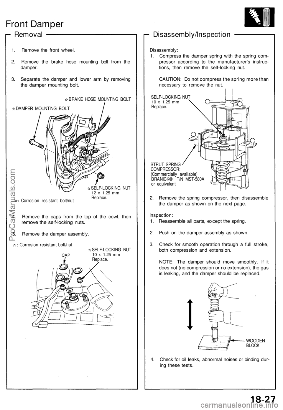
Removal
1. Remove the front wheel.
2. Remove the brake hose mounting bolt from the
damper.
3. Separate the damper and lower arm by removing
the damper mounting bolt.
BRAKE HOSE MOUNTING BOLT
DAMPER MOUNTING BOLT
Corrosion resistant bolt/nut
SELF-LOCKING NUT
12 x
1.25
mm
Replace.
4. Remove the caps from the top of the cowl, then
remove the self-locking nuts.
5. Remove the damper assembly.
Corrosion resistant bolt/nut
CAP
SELF-LOCKING NUT
10 x
1.25
mm
Replace.
Disassembly/Inspection
Disassembly:
1. Compress the damper spring with the spring com-
pressor according to the manufacturer's instruc-
tions, then remove the self-locking nut.
CAUTION: Do not compress the spring more than
necessary to remove the nut.
SELF-LOCKING NUT
10 x
1.25
mm
Replace.
STRUT SPRING
COMPRESSOR:
(Commercially available)
BRANICK® T/N MST-580A
or equivalent
2. Remove the spring compressor, then disassemble
the damper as shown on the next page.
Inspection:
1. Reassemble all parts, except the spring.
2. Push on the damper assembly as shown.
3. Check for smooth operation through a full stroke,
both compression and extension.
NOTE: The damper should move smoothly. If it
does not (no compression or no extension), the gas
is leaking, and the damper should be replaced.
WOODEN
BLOCK
4. Check for oil leaks, abnormal noises or binding dur-
ing these tests.ProCarManuals.com
Page 491 of 1640
Special Tools
Ref.
No.
Tool Number
07HAA – SG00100 or
07HAA – SG00101
07HAE – SG00100
07HAJ – SG00100or
07HAJ – SG0010B
07JAG – SD40100
07KA2 – 001000A
07914 – SA50000
Description
Bleeder T-Wrench
Brake Spring Compressor
ALB Checker (US)
Pushrod Adjustment Gauge
Auxiliary Window Switch
Snap Ring Pliers
Qty
1
1
1
1
1
1
Page Reference
19-62('91-'92)('93-'96),64('91-'92)('93-'96),65('91-'92)
('93-'96),69('91-'92)('93-'96)
19-21, 24
19-41, 43, 64('91-'92)('93-'96),
69('91-'92)('93-'96)
19-15
19-65('91-'92)('93-'96)
19-21,
24
ProCarManuals.com