Page 353 of 1273

FUEL SYSTEM - Troubleshooting13-211
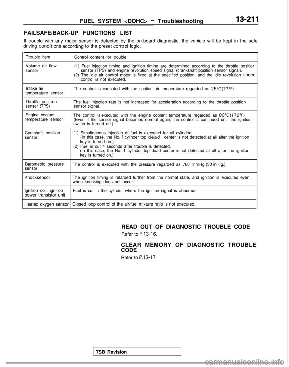
FAILSAFE/BACK-UP FUNCTIONS LIST
If trouble with any major sensor is detected by the on-board diagnostic,\
the vehicle will be kept in the safe
driving conditions-accdrding
to the preset control
logic.
Trouble item
Volume air flow
sensor Control content for trouble
(1) Fuel injection timing and ignition timing are determined according\
to the throttle positior
sensor (TPS) and engine revolution speed signal (crankshaft position \
sensor signal).
(2) The idle air control motor is fixed at the specified position, and\
the idle revolution speec
control is not executed.
Intake air
temperature sensor The control is executed with the suction air temperature regarded as
25’C (77°F).
Throttle positron
sensor (TPS)The fuel injection rate is not increased for acceleration according to t\
he throttle positionsensor signal.
Engine coolant
temperature sensor The control IS executed with the engine coolant temperature regarded as 80°C
(176°F).(Even if the sensor signal becomes normal again, the control is continu\
ed until the ignition
switch is turned off.)
Camshaft position
sensor (1) Simultaneous injection of fuel is executed for all cylinders.
(In this case, the No.
1 cylinder top dead center is not detected at all after the ignition
key is turned on.)
(2) Fuel is cut 4 seconds after trouble is detected. (In this case, the No. 1 cylinder top dead center IS not detected at all after the ignition
key is turned on.)
Barometric pressure
sensor The control is executed with the pressure regarded as 760
mmHg (30 in.Hg.).
Knocksensor
The ignition timing is retarded further from the normal state, and ignit\
ion is executed even
when knocking does not occur.
Ignition coil, ignition
power transistor unitFuel is cut in the cylinder where the ignition signal is abnormal.
Heated oxygen sensor Closed loop control of the air/fuel mixture ratio is not executed.
TSB RevisionREAD OUT OF DIAGNOSTIC TROUBLE CODE
Refer to
P.13-16.
CLEAR MEMORY OF DIAGNOSTIC TROUBLE
CODE
Refer to P.13-17.
Page 354 of 1273
Page 365 of 1273
FUEL SYSTEM - Troubleshooting
13-223
JE
I
MFIRELAY
A-40
IEEl
$92
B
EGHS@LENOID(VHEICLES FORCALIFORNIA)
0365
1Y I1 BATTERY BACK UP j
@2
1 FUSIBLE LIN
'6
A-07X r
>c
DUAL
DmREA-21 OF;-
@i
AUTO COMPRESSOR;ONTROG UNIT
12 c-23
2
m
1
I$$;i?~pP”lIFJ;WPkP.a
ON:2100kPe(29QPS 1)IIOFF:2700kPaf384PS I)
1
'A-06
ENGINE COOLANT
IMAGNETIC CLUTCH
MFI CONTROL UNIT'
KX35-AC-HOSeBE-NY
TSB Revision1
Page 373 of 1273
FUEL SYSTEM - Troubleshooting13-231
4:
;zs1.25-R10
'1;rOLUK!Z AIR FLOW SENSOR
ANDA-47
12
m
I1221 t%TE!OL UNI
T
“? I@ 1 Yi Y
qEqsrp---~--~g---[~---------;;-~4 iuY&ii’------
1 mi mi E I
wT”ill’li
I II’-1 q-1’ I
f I I IT-11 I l-ijdrnl &$$$I I
i IIIII
z III
a
2 1
0
KNOCK
u
SENSOR
EII WI- CLiiEDdTHROTTLE =ENGINE
COOLANTTHROTTLE-l'#;&ON
##@ATURE @&ONB-22-2mEl %HEATED
OXYGEN SENSOR
1
1iB-04-1
B-02 Il!dB-02-1-B-20OXYGEN SENSORg@ e
CHECK CONNECTOR
m c-14H
l-
L
xX35-Ac-n0537wiu
,
TSB RevisionI
Page 375 of 1273
FUEL SYSTEM - Troubleshootina
SUB FUSIBLE LIh
I
A-48
m
;I2Ll
z
ku2
i
I
E
??
is
1
1
EGK
x
SOLENOIDWHEICLES FORCALIFORNIA)
2
E
E-
r
A-07X
El3
4
IK
T
>
si
EFATEDA
AUTO COMPRESSOR
CONTROL UNIT
;E56
A3 ,,4.
:
‘o/
‘12 c-23
6 A-08 : : : ::lIIxB3
1 AIR
1
CONDITIONING
ENGINE COOLANT
I ;E&#$TURE
! 8F~!?8;%!~~&Fk1
IJMAGNETIC CLUTCHMFI CONTROL UNIT
KX35-AC-H03378-NW
TSB Revision
Page 380 of 1273
13-238FUEL SYSTEM - Troubleshooting
CIRCUIT DIAGRAM (CONTINUED)
FUSIBLE LINFsv
kJT0 COMPRESSORCONTROL UNIT
c-30 E
A-07-2X
$-231
IOD OR
~6oNFIK%OF
I
3
L2Ei
E
,234 C-37-l
J/B
MFIRELAY
Bkc-39
6A-07X
Els4
A-48
mA-08
I
AIRCONDITIONING
ENGINE COOLANT
g rfIi EFiTURE
@;j&FJQgQ'~.)
IB-22 I
103t%d, 1.
E
a 53c-10
V
B-05I J--
I
IMAGNETIC CLUTCH
MFI CONTROL UNITKX35-AC-HO53QB-NY
TSB Revision
Page 387 of 1273

FUEL SYSTEM - Service Adjustment Procedures13-245
cl989 models> -a’i\.-upI t
SERVICE ADJUSTMENT PROCEDURES
CURB IDLE SPEED INSPECTION
MlSFHAB
(1) The vehicle should be prepared as follows before the inspection.
l Engine coolant temperature:
85-95°C (185-205°F)
l Lights, electric cooling fan and accessories: OFF
l Transaxle: Neutral
(P for vehicles with an automatic
transaxle)
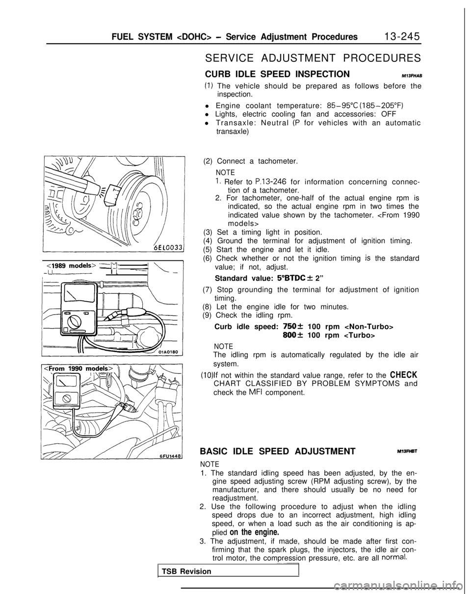
(2) Connect a tachometer.
NOTE
1. Refer to P.13-246 for information concerning connec-
tion of a tachometer.
2. For tachometer, one-half of the actual engine rpm is
indicated, so the actual engine rpm in two times the
indicated value shown by the tachometer.
models>
(3) Set a timing light in position.
(4) Ground the terminal for adjustment of ignition timing.
(5) Start the engine and let it idle.
(6) Check whether or not the ignition timing
is the standard
value; if not, adjust.
Standard value:
5”BTDC f 2”
(7) Stop grounding the terminal for adjustment of ignition timing.
(8) Let the engine idle for two minutes.
(9) Check the idling rpm.
Curb idle speed:
75Ok 100 rpm
800+ 100 rpm
NOTE
The idling rpm is automatically regulated by the idle airsystem.
(10)lf not within the standard value range, refer to the CHECK
CHART CLASSIFIED BY PROBLEM SYMPTOMS and
check the
MFI component.
BASIC IDLE SPEED ADJUSTMENT
Ml3FHBl
NOTE
1. The standard idling speed has been adjusted, by the en- gine speed adjusting screw (RPM adjusting screw), by the
manufacturer, and there should usually be no need for
readjustment.
2. Use the following procedure to adjust when the idling speed drops due to an incorrect adjustment, high idling
speed, or when a load such as the air conditioning is ap-
plied on the engine.
3. The adjustment, if made, should be made after first con- firming that the spark plugs, the injectors, the idle air con-trol motor, the compression pressure, etc. are all
normal.~~-
TSB Revision
Page 388 of 1273

13-246FUEL SYSTEM - Sewice Adjustment Procedures
17k&---,!E~,~~/iY I
(1) The vehicle should be prepared as follows before the
inspection and adjustment.
l Engine coolant temperature:
85-95°C (185-205°F)
l Lights, electric cooling fan and accessories: OFF l Transaxle: Neutral (P for vehicles with an automatic transaxle)
(2) Connect the scan tool to the data link connector (white).
NOTE
When the scan tool is connected, the diagnostic test mode
control terminal is grounded.
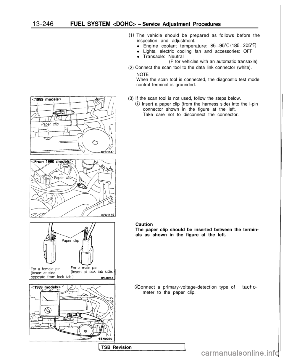
(3) If the scan tool is not used, follow the steps below.
@ Insert a paper clip (from the harness side) into the l-pin connector shown in the figure at the left.
Take care not to disconnect the connector.
/ Paper chp -
f!f--i!t
Ah
-II
For a female pin
For a male
ptn (Insert
at side (Insert
at
lock tab side.
opposite from
lock
tab.)OlL0246
Caution
The paper clip should be inserted between the termin-
als as shown in the figure at the left. @ Connect a primary-voltage-detection type of
tacho-
meter to the paper clip.
TSB Revision