1989 MITSUBISHI GALANT engine coolant
[x] Cancel search: engine coolantPage 260 of 1273
13418FUEL SYSTEM (SOHC-16 VALVE> - Specifications
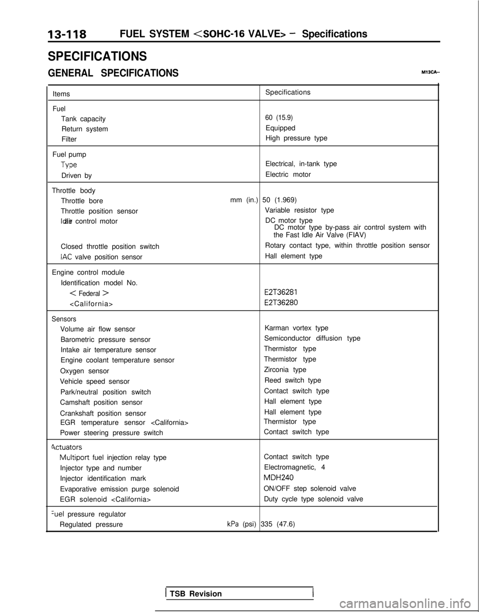
SPECIFICATIONS
GENERAL SPECIFICATIONSMISCA-
Items
Fuel
Tank capacityReturn system
Filter
Fuel pump Type
Driven by
Throttle body Throttle bore
Throttle position sensor Idle air control motor
Closed throttle position switch
IAC valve position sensor
Engine control module Identification model No.
< Federal >
Sensors
Volume air flow sensorBarometric pressure sensor
Intake air temperature sensor
Engine coolant temperature sensor
Oxygen sensor
Vehicle speed sensor
Park/neutral position switch
Camshaft position sensor
Crankshaft position sensor EGR temperature sensor
Power steering pressure switch
Cvctuators
Multiport fuel injection relay type
Injector type and number
Injector identification mark
Evaporative emission purge solenoid
EGR solenoid
pressure regulator
Regulated pressure Specifications
60 (15.9)
Equipped
High pressure type
Electrical, in-tank type
Electric motor
mm (in.) 50 (1.969) Variable resistor typeDC motor type DC motor type by-pass air control system with
the Fast Idle Air Valve (FIAV)
Rotary contact type, within throttle position sensor
Hall element type
E2T36281 E2T36280
Karman vortex type
Semiconductor diffusion type
Thermistor type
Thermistor type Zirconia type
Reed switch type
Contact switch type Hall element type
Hall element type
Thermistor type
Contact switch type
Contact switch type
Electromagnetic, 4 MDH240
ON/OFF step solenoid valve Duty cycle type solenoid valve
kPa (psi) 335 (47.6)
1 TSB Revision
Page 261 of 1273
Specifications/Special Tools/FUEL SYSTEM
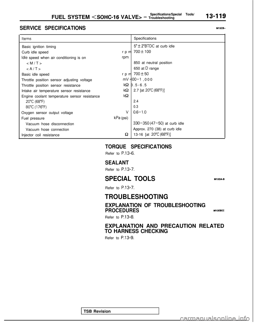
SERVICE SPECIFICATIONS
13-119 MlOCB-
Items
Specifications
Basic ignition timing
5”f 2”BTDC at curb idle
Curb idle speed rpm
700-C 100
Idle speed when air conditioning is onvm
850 at neutral position
650 at
D range
Basic idle speed rpm
700+50
Throttle position sensor adjusting voltagemV 400-I ,00
0
Throttle position sensor resistance
kQ 3.5-6.
5
Intake air temperature sensor resistance
kQ2.7 [at 20°C (68”F)]
Engine coolant temperature sensor resistancekQ
20°C (68°F)2.4
80°C (176°F) 0.3
Oxygen sensor output voltageV 0.6-1.0
Fuel pressurekPa (psi)
Vacuum hose disconnection
330-350 (47-50) at curb idle
Vacuum hose connection Approx. 270 (38) at curb idle
Injector coil resistance
5213-16 [at 20°C (68”F)]
TSB Revision
TORQUE SPECIFICATIONS
Refer to P.13-6.
SEALANT
Refer to
P.13-7.
SPECIAL TOOLS
Refer to
P.13-7.
MlBDA-B
TROUBLESHOOTING
EXPLANATION OF TROUBLESHOOTING
PROCEDURES
MllEBCC
Refer to P.13-8.
EXPLANATION AND PRECAUTION RELATED
TO HARNESS CHECKING
Refer to P.13-9.
Page 262 of 1273
13-120FUEL SYSTEM
CHH;K
ENGINE/MALFUNCTION INDICATOR
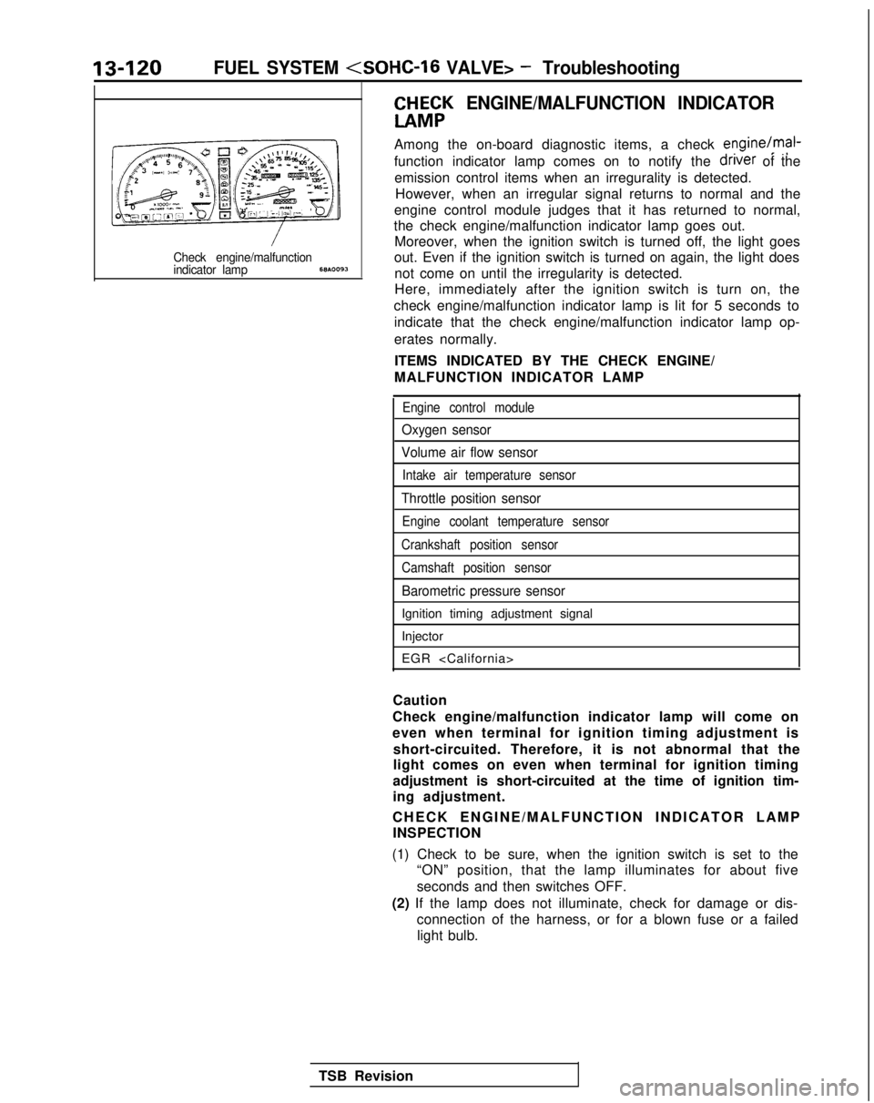
Among the on-board diagnostic items, a check engine/mal-
function indicator lamp comes on to notify the driver
of the
emission control items when an irregurality is detected. However, when an irregular signal returns to normal and the
engine control module judges that it has returned to normal,
the check engine/malfunction indicator lamp goes out. Moreover, when the ignition switch is turned off, the light goes
Check engine/malfunctionout. Even if the ignition switch is turned on again, the light doesindicator lamp68A.0093not come on until the irregularity is detected.
Here, immediately after the ignition switch is turn on, the
check engine/malfunction indicator lamp is lit for 5 seconds to indicate that the check engine/malfunction indicator lamp op-
erates normally.
ITEMS INDICATED BY THE CHECK ENGINE/
MALFUNCTION INDICATOR LAMP
Engine control module
Oxygen sensor
Volume air flow sensor
Intake air temperature sensor
Throttle position sensor
Engine coolant temperature sensor
Crankshaft position sensor Camshaft position sensor
Barometric pressure sensor
Ignition timing adjustment signal
Injector
EGR
Caution
Check engine/malfunction indicator lamp will come on
even when terminal for ignition timing adjustment is short-circuited. Therefore, it is not abnormal that the
light comes on even when terminal for ignition timing
adjustment is short-circuited at the time of ignition tim-
ing adjustment.
CHECK ENGINE/MALFUNCTION INDICATOR LAM
P
INSPECTION
(1) Check to be sure, when the ignition switch is set to the “ON” position, that the lamp illuminates for about five
seconds and then switches OFF.
(2) If the lamp does not illuminate, check for damage or dis- connection of the harness, or for a blown fuse or a failedlight bulb.
TSB Revision
Page 264 of 1273
13-122FUEL SYSTEM
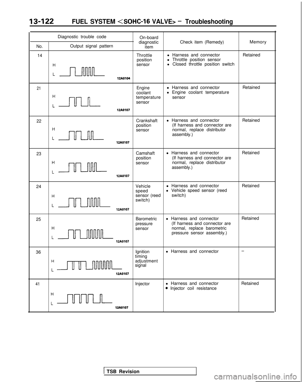
Diagnostic trouble codeOn-board
diagnostic Check item (Remedy) Memory
No.Output signal pattern
item
14Throttlel Harness and connector
Retained
position l Throttle position sensor
:n
sensor l Closed throttle position switch
12Ao104
21Enginel Harness and connector
Retained
coolant l Engine coolant temperature
Cnn
temperature
sensor
sensor
lzAO107
22Crankshaft l Harness and connector
Retained
position (If harness and connector are
:nn
sensor normal, replace distributor
assembly.)
lzAOlO7
23Camshaft l Harness and connector
Retained
position (If harness and connector are
:-
sensor normal, replace distributor
assembly.)
12Ao107
24 Vehiclel Harness and connector
Retained
speed l Vehicle speed sensor (reed
Hsensor (reed
switch)
switch)
LULl-uulnlzAO107
25
H
Barometric
pressure l Harness and connector
(If harness and connector are
LULMlvul
sensor normal, replace barometric
pressure sensor assembly.)
VA0107
Retained
36 Ignition
l Harness and connector
-
timingH
Lu u LnllMnn
adjustment
signal
12Ao107
41Injector l Harness and connector0 Injector coil resistance Retained
12Ao107
1 TSB Revision
Page 266 of 1273
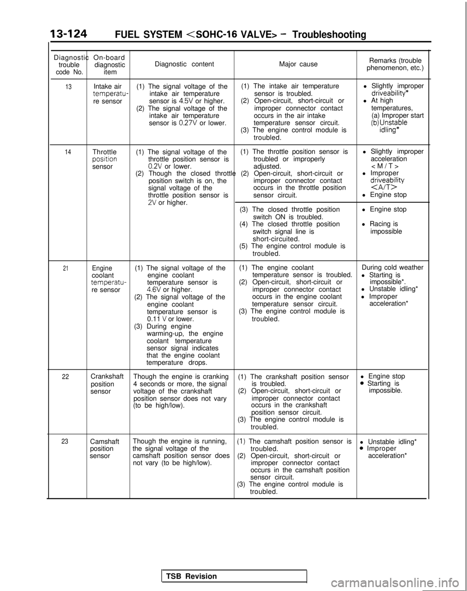
13-124FUEL SYSTEM
Diagnostic On-board
trouble diagnostic
code No.item Diagnostic content
Major causeRemarks (trouble
phenomenon, etc.)
13
14Intake air (1) The signal voltage of the (1) The intake air temperature
l Slightly impropertemperatu-intake air temperature
sensor is troubled.driveability*
re sensorsensor is 4.5V or higher.(2) Open-circuit, short-circuit or
l At high
(2) The signal voltage of the improper connector contacttemperatures,
intake air temperature occurs in the air intake (a) Improper start
sensor is
0.27V or lower. temperature sensor circuit.
(3) The engine control module isiWJ;sn$aple
troubled.
Throttle (1) The signal voltage of the (1) The throttle position sensor is
l Slightly improperposltion
throttle position sensor is troubled or improperly acceleration
sensor
0.2V or lower. adjusted.
(2) Though the closed throttle (2) Open-circuit, short-circuit or l Improper
position switch is on, the improper connector contact
signal voltage of the occurs in the throttle position
d&eTbQ
throttle position sensor is
sensor circuit. l Engine stop2V or higher.
(3) The closed throttle position l Engine stop
switch ON is troubled.
(4) The closed throttle position l Racing is
switch signal line is impossible
short-circuited.
(5) The engine control module is
troubled.
21Engine(1) The signal voltage of the (1) The engine coolant
During cold weather
coolant engine coolant temperature sensor is troubled.
l Starting is
temperatu-temperature sensor is(2) Open-circuit, short-circuit or
impossible*.
re sensor4.6V or higher. improper connector contact l Unstable idling*
(2) The signal voltage of the occurs in the engine coolant
l Improper
engine coolant temperature sensor circuit. acceleration*
temperature sensor is (3) The engine control module is
0.11
V or lower. troubled.
(3) During engine warming-up, the engine
coolant temperature
sensor signal indicates
that the engine coolant
temperature drops.
22Crankshaft Though the engine is cranking (1) The crankshaft position sensor l Engine stop
position 4 seconds or more, the signal is troubled.0 Starting is
sensor voltage of the crankshaft (2) Open-circuit, short-circuit or impossible.
position sensor does not vary improper connector contact
(to be high/low). occurs in the crankshaft
position sensor circuit.
(3) The engine control module is
troubled.
23Camshaft Though the engine is running,(1) The camshaft position sensor is
l Unstable idling*
position the signal voltage of the
troubled.0 Improper
sensor camshaft position sensor does
(2) Open-circuit, short-circuit or acceleration*
not vary (to be high/low). improper connector contact
occurs in the camshaft position
sensor circuit.
(3) The engine control module is
troubled.
TSB Revision
Page 268 of 1273
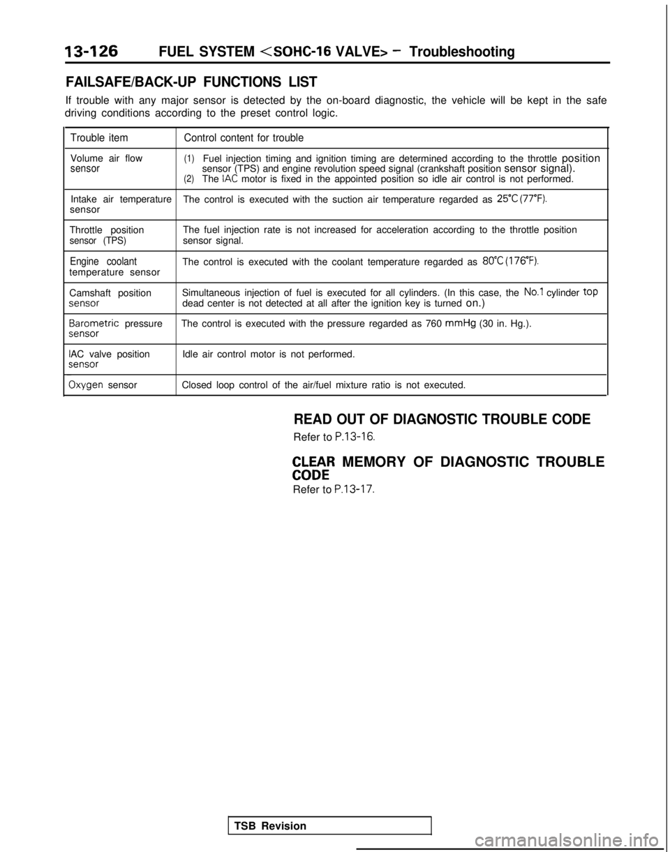
13-126FUEL SYSTEM
FAILSAFE/BACK-UP FUNCTIONS LIST
If trouble with any major sensor is detected by the on-board diagnostic,\
the vehicle will be kept in the safe
driving conditions according to the preset control logic.
Trouble item Control content for trouble
Volume air flow(1)Fuel injection timing and ignition timing are determined according to th\
e throttle positionsensorsensor (TPS) and engine revolution speed signal (crankshaft position \
sensor signal).(2)The IAC motor is fixed in the appointed position so idle air control is not per\
formed.
Intake air temperature The control is executed with the suction air temperature regarded as
25°C (77°F).sensor
Throttle position The fuel injection rate is not increased for acceleration according to t\
he throttle position
sensor (TPS)sensor signal.
Engine coolantThe control is executed with the coolant temperature regarded as 80°C (176’F).temperature sensor
Camshaft positionSimultaneous injection of fuel is executed for all cylinders. (In this \
case, the
No.1 cylinder top
jenS0r
dead center is not detected at all after the ignition key is turned
on.)3arometric
pressure The control is executed with the pressure regarded as 760 mmHg
(30 in. Hg.).
sensor
AC valve position Idle air control motor is not performed.;ensor
Ixygen sensor
Closed loop control of the air/fuel mixture ratio is not executed.
READ OUT OF DIAGNOSTIC TROUBLE CODE
Refer to P.13-16.
EbW&R MEMORY OF DIAGNOSTIC TROUBLE
Refer to
P.13-17.
TSB Revision
Page 269 of 1273
FUEL SYSTEM
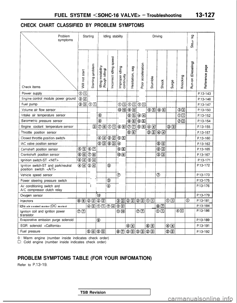
CHECK CHART CLASSIFIED BY PROBLEM SYMPTOMS
ProblemsymptomsStartingIdling stability Drivingr”
.-
%scn
E5
$4.a,o_
5;i
cz
iP.13-143
-
Ea,Ll2a
F.- s
G-
DE-
c-
Elc
-
-
>El
)El-
)I3-
)@I
I-
-
i
-
5‘32a,$%ba”
D&l DEI
i>El
-0%,a>+y -2.gPE.-50 z.E r2?p9 6=& g-
-
-Sheck items
‘ower
supply
%ginecontrol module power groundI
1 P.13-146
:uel pump
Jolume air flow sensor
B
f
E3
DELI @El
cP.13-162
P.13-165III P.13-167I
1/ P.l3-171 1
P.l3-172
P.l3-173
P.l3-175
P.13-176
P.l3-179
ntake air temperature sensor
BIB
DEI
0
DEl
3El
3
-I
iarometric
pressure sensor
ingine coolant temperature
sensor
‘hrottle position sensor
Iosed throttlepositionswitch
K valve oosition sensor
lamshaft position sensor
i-:rankshaft positionsensorIIlnition
switch-ST
-I---0lnition switch-ST and park/neutralosition switch
chicle
speed sensor
ower steering pressure switch
ir conditioning switch and/C compressor clutch relayI/I- IIlxygen sensor
@El@ P.l3-181
@ElP.13-184
@[email protected]
Ile air control motor (DC motor)
inition coil and ignition powerOFI@piJOEIansistor
tiaporative emission purge solenoid01 P.13-189
1 Id
kl
c
tr
t
EGR solenoid
Fuel pressureOIlI @El8E.l @El @El @[email protected]
0 : Warm engine (number inside indicates check order)
0 : Cold engine (number inside indicates check order)
PROBLEM SYMPTOMS TABLE (FOR YOUR INFOMATION)
Refer to P.13-19.
TSB Revision
Page 275 of 1273

FUEL SYSTEM
FUEL TANK AND FUEL LINEMIBEAAB
Symptom
Probable cause Remedy
Engine malfunctions
due to insufficient
fuel supply Bent or kinked fuel pipe or hose
Clogged fuel pipe or hose
Clogged fuel filter or in-tank fuel filter
Water in fuel filter Repair or replace
Clean or replace
Replace
Replace the fuel filter or clean the
fuel tank and fuel line
Dirty or rusted fuel tank interior
Clean or replace
Malfunctioning fuel pump
(Clogged filter in the pump)Replace
Evaporative emission
control system
malfunctions
[When fuel tank filler
tube cap is removed,
pressure releasingnoise is heard) Mispiping of vapor line
Disconnected vapor line piping joint
Folded, bent, cracked or clogged vapor line
Faulty fuel tank filler tube cap
Malfunctioning fuel tank pressure control valve Correct
Correct
Replace
Replace
Replace
SERVICE ADJUSTMENT
PROCEDURES
CURB IDLE SPEED INSPECTIONhll3MAE
(1) The vehicle should be prepared as follows before th
e
inspection.
lEngine coolant temperature: 85-95°C (185-203°F)
l Lights, electric cooling fan and accessories: OFF
l Transaxle: Neutral (P for vehicles with an automatic
transaxle)
(2) Connect a tachometer.
NOTE
Refer to
P.13-134 for information concerning connection Of
a tachometer.
(3) Set a timing light in position.
(4) Ground the terminal for adjustment of ignition timing.
(5) Start the engine and let it idle.
(6) Check whether or not the ignition timing is the standard
value; if not, adjust.
Standard value:
5”BTDC f 2”
(7) Stop grounding the terminal for adjustment of ignition timing.
(8) Let the engine idle for two minutes.
(9) Check the idling rpm.
Curb idle speed: 700
31100 rpm
NOTE
The idling rpm is automatically regulated by the idle aircontrol system.
(lO)lf not within the standard value range, refer to the CHECK
CHART CLASSIFIED BY PROBLEM SYMPTOMS and check
the
MFI component,
TS6 Revision1