Page 276 of 1273
13-134FUEL SYSTEM (SOHC-16 VALVE> -Service Adjustment Procedures
BASIC IDLE SPEED ADJUSTMENTMlIFHBX
NOTE
1. The standard idling speed has been adjusted, by the en-
gine speed adjusting screw, by the manufacturer, and
there should usually be no need for readjustment.
2. Use the following procedure to adjust when the idling speed drops due to an incorrect adjustment, high idling
speed, or when a load such as the air conditioning is ap-
plied on the engine.
3. The adjustment, if made, should be made after first con- firming that the spark plugs, the injectors, the idle air con-
trol motor, the compression pressure, etc. are all normal.
(I ) The vehicle should be prepared as follows before the inspec- tion and adjustment.
l Engine coolant temperature:
85-95°C (185-203°F)
l Lights, cooling fan and accessories: OFF
l Transaxle: neutral (A/T for
P range)
l Steering wheel: neutral position
(2) Connect the scan tool to the data link connector (white).
NOTE
When the scan tool is connected, the diagnostic test mode control terminal should be grounded.
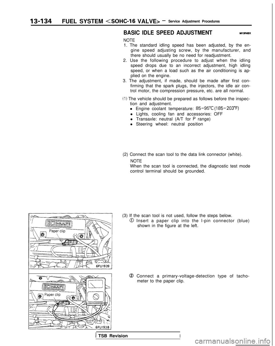
(3) If the scan tool is not used, follow the steps below.
@I Insert a paper clip into the l-pin connector (blue) shown in the figure at the left.
0 Connect a primary-voltage-detection type of tacho-meter to the paper clip.
1 TSB RevisionI
Page 278 of 1273
13-136FUEL SYSTEM
VALVE>- Service Adjustment Procedures
TPS connector
7FUO629
THROTTLE BODY (THROTTLE VALVE AREA)
CLEANINGMl3Rcv
(1)Start the engine and warm it up until the engine coolant is
heated to
80°C (176°F) or higher and then stop the engine.
(2)Remove the air intake hose from the throttle body.
(3)Plug the bypass passage inlet of the throttle body.
Caution
Do not allow cleaning solvent to enter the bypass
passage.
(4)Spray cleaning solvent into the valve through the throttle
body intake port and leave it for about 5 minutes.
(5)Start the engine, race it several times and idle it for about 1 minute. If the idling speed becomes unstable (or if the
engine stalls) due to the bypass passage being plugged,
slightly open the throttle valve to keep the engine
running.
(6)If the throttle valve deposits are not removed, repeat steps
(4) and (5).
(7)Unplug the bypass passage inlet.
(8)Attach the air intake hose.
(9)Use the scan tool to erase the diagnostic trouble code.
(10) Adjust the basic idle speed. (Refer to
P.13-134.)
NOTE
If the engrne hunts when idling after adjustment of the basic
idle speed, remove the
@ cable from the battery for 10
seconds or more, and then run the engine at idle again.
CLOSED THROTTLE POSITION SWITCH AND
THROTTLE POSITION SENSOR ADJUSTMEy,zIFF
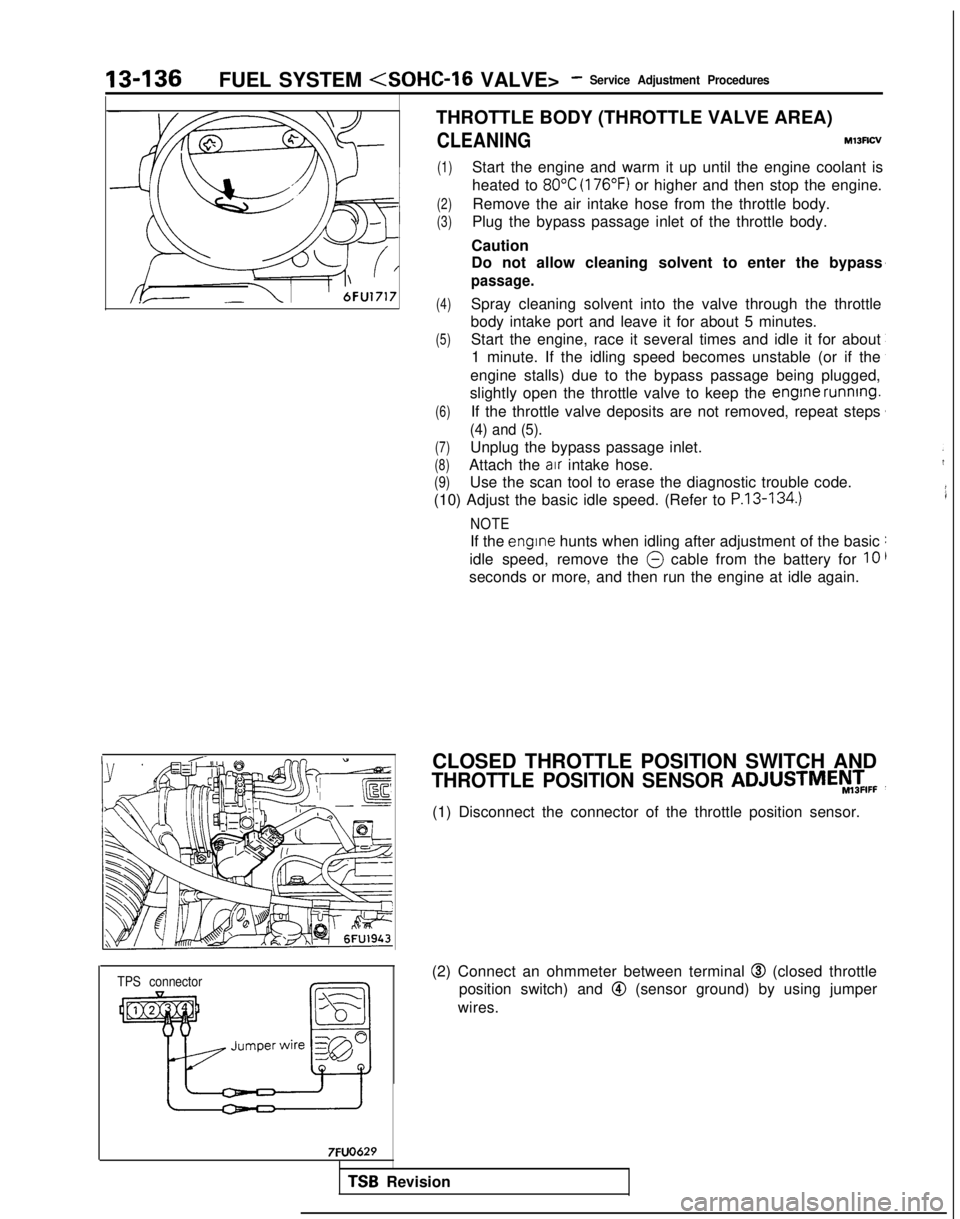
(1) Disconnect the connector of the throttle position sensor.
(2) Connect an ohmmeter between terminal
@I (closed throttle
position switch) and
@ (sensor ground) by using jumper
wires.
TSB Revision
Page 281 of 1273
FUEL SYSTEM - ?::;:r%t~pection Of MF’13439
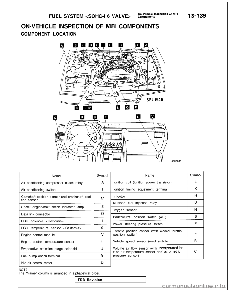
ON-VEHICLE INSPECTION OF MFI COMPONENTS
COMPONENT LOCATION
6FUO843
Name Symbol NameSymbol
Air conditioning compressor clutch relay A
Ignition coil (ignition power transistor)
L
Air conditioning switchTIgnition timing adjustment terminalK
Camshaft position sensor and crankshaft posi- InjectorHMtion sensor- Multiport fuel injection relayU
Check engine/malfunction indicator lampS- Oxygen sensorN
Data link connectorQ- Park/Neutral position switch (A/T)6
EGR solenoid I- Power steering pressure switchP
EGR temperature sensor 0
Throttle position sensor (with closed throttle
position switch)
EEngine control modulev
Engine coolant temperature sensorFVehicle speed sensor (reed switch)R
Evaporative emission purge solenoidJVolume air flow sensor (with incorporated,in-
take air temperature sensor and barometncC
Fuel pump check terminalGpressure sensor)
Idle air control motor
D
NOTEThe “Name” column is arranged in alphabetical order. TSB Revision
Page 292 of 1273
On-Vehicle Inspection of MFI
13450FUEL SYSTEM
VALVE> - Components
VOLUME AIR FLOW SENSOR
Intake air amountWsec)16245
1
@ Componentsideconnectof
Multiport
fuel
injection relay
/ohme air flow sensor/\2/\-
@Harness side
Isv xI 6FU1952
OPERATION TROUBLESHOOTING HINTSRefer to
P.13-49.
INSPECTION
Using Scan Tool
Item No.
12
Data displayInspection conditions Engine condition
Standard value
Sensor de- . Engine coolant Idle speed
18-44 Hz
tection airtemperature: 85-95°C
volume (fre- (185-205°F)
quency)
. Lights, cooling fan, elec-
2,000 rpm64-l 04 Hz tricaI
accessories: OFF
Transaxle: neutral
(PJTmodels: “P” range)RacingFrequency in-
creases as racing rpm increases.
NOTE
The volume air flow sensor output frequency may be about 10% higher than\
indicated above when the vehicle is new[driven approximately 500 km (300 miles) or less].
TSB Revision
1
Page 297 of 1273
FUEL SYSTEM - ::~,%~t~pection Of MF’13-155
L-J
2@ Harness side
@ Harness stde
connector Engine control
module harness
side connector
r----l65
mr01AO107
~Check for an open circuit, or a short-
circuit to ground between the engine
:control module and the barometric
pressure sensor.
il Volume air flow sensor connec-
tor: Disconnected
l Engine control module connec-
tor: Disconnected
Measure the impressed voltage of the
barometric pressure sensor.
l Volume air flow sensor connec- tor: Disconnected
l Engine control module connec-
tor: Connected
l Ignition switch: ON
Voltage
(VI
Replace
- the engine 1
control
module.
IOIAO233 I4.8 - 5.2I
Engrne coolant
Engine coolant
@ Equipment temperature sensorside connector
Enginecontrol
module
72
6
3
I fh5v
Engine coolanttemoerature
Engine control module connector
7FW6!53
9FUO106
TSB Revision
Page 298 of 1273
13-156On-Vehicle Inspection of MFI
FUEL SYSTEM (SOHC-16 VALVE> - Components
OPERATION
TROUBLESHOOTING HINTS INSPECTION
Using Scan Tool
Refer to
P.13-55.
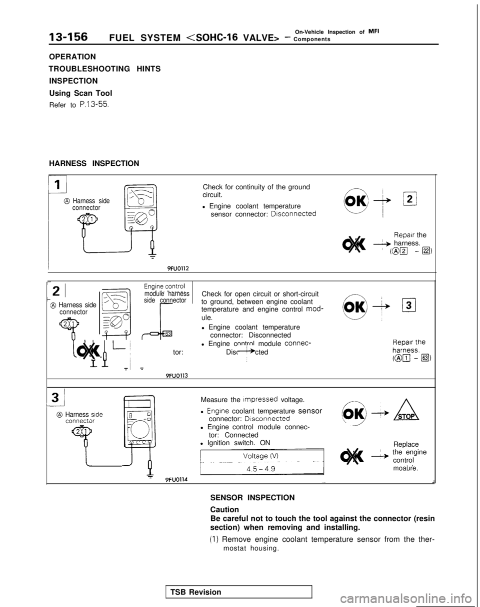
HARNESS INSPECTION
Harness side
connector
Check for continuity of the ground
circuit.
l Engine coolant temperature sensor connector: Drsconnected
9FUO112
01
OK+ /2/
Repair the
& harness.
i @lz -@i,
r
21t@ Harness sideconnector
2 1
7
Check for open circuit or short-circuit
to ground, between engine coolant
temperature and engine control mod-
!:I->,
OK+ 131
ule.
l Engine coolant temperature
connector: Disconnected
l Engine control module connec-
~ 1 h h L
~
tor: Disconnected$)#!& ” g$jnii
7 7
c
module harness
side connector
9FUO113
3
@ Harness side connectx
Measure the Impressed
voltage.
l Engine coolant temperature sensor
connector: Dlsconnected
l Engine control module connec- tor: Connected
l Ignition switch. ON Replace
& the engine
control ,
I
9FUO114
moaure.
SENSOR INSPECTION
Caution
J
Be careful not to touch the tool against the connector (resin
section) when removing and installing.
(1) Remove engine coolant temperature sensor from the ther- mostat housing.
TSB Revision
Page 299 of 1273
FUEL SYSTEM (SOHC-16 VALVE> - ::ii,,k%ti=pec*ion Of MF’13-157
9FUO156
9FUO157
THROTTLE POSITION SENSOR
MinimumMaxlmum
Throttle shaft turning angle162461
(21 With temperature sensing portion of engine coolant tem-
perature sensor immersed in hot water, check resistance
Temperature PC (“F)lResistance (k!S)
0 (32)5.8
I20 (68)~12.4I
I80 (I 76)I0.3I
Engine control module connector
(3) If the resistance deviates from the standard value greatly,
replace the sensor.
INSTALLATION
(1) Apply sealant to threaded portion. Specified sealant:
3M NUT locking Part No. 4171 or
equivalent
(2) Install engine coolant temperature sensor and tighten it to specified torque.
Sensor tightening torque:
20-40 Nm (15-29 ft.lbs.)
(3) Fasten harness connectors securely.
@ Equipment sideconnectorThrottle posltlon sensor
@ Harness srdeconnector
pJ$q]
1
5EL1400
I72-
E
6461
r 1
Engine control module
7FUO672
L
7FUO653
1 TSB Revision
Page 305 of 1273
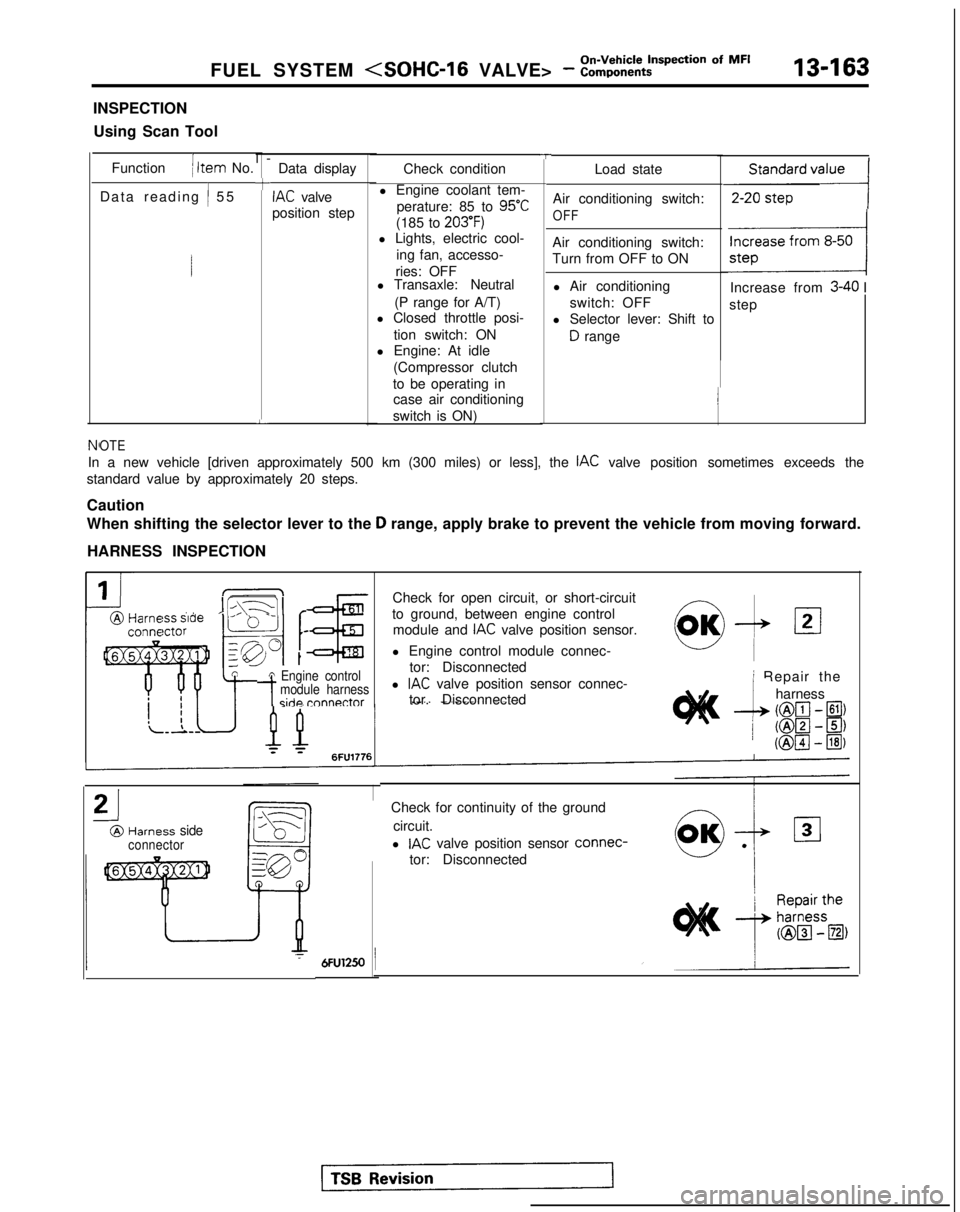
FUEL SYSTEM - :::,:k:t?=tiion Of MF’13-163
INSPECTION
Using Scan Tool
Function
( Item No.
Data reading
/ 5
5
l-
+
L
Data display
IAC valve
position step
TCheck condition
l Engine coolant tem- perature: 85 to
95°C
(185 to 203’F)l Lights, electric cool- ing fan, accesso-
ries: OFF
l Transaxle: Neutral
(P range for A/T)
l Closed throttle posi-
tion switch: ON
l Engine: At idle
(Compressor clutch
to be operating in case air conditioning
switch is ON) Load state
Air conditioning switch:
OFF
Air conditioning switch:
Turn from OFF to ON l Air conditioning switch: OFF
l Selector lever: Shift to
D range
,,,,,,,,,I
Increase from 3-40 I
step
NfOTE
In a new vehicle [driven approximately 500 km (300 miles) or less], th\
e IAC valve position sometimes exceeds the
standard value by approximately 20 steps.
Caution
When shifting the selector lever to the
D range, apply brake to prevent the vehicle from moving forward.
HARNESS INSPECTION
IIL\-11 r@Harm ” ’ -conna
tA Engine control
-tmodule harnessside rnnnnctor
Check for open circuit, or short-circuit
to ground, between engine control module and
IAC valve position sensor.
l Engine control module connec- tor: Disconnected
l
IAC valve position sensor connec-
tor. Disconnected
21
@Harness sideconnector
0,OK-& 121
i Repair the
--L
harness
(@lcl- El)
/ ml-~) (@pJ
- @I)
Check for continuity of the ground
circuit.
l
IAC valve position sensor connec-
tor: Disconnected