1989 MITSUBISHI GALANT engine coolant
[x] Cancel search: engine coolantPage 390 of 1273
13-248FUEL SYSTEM
(8) Switch OFF the ignition switch.
(9) If the scan tool was not used, disconnect the jumper wire from the diagnostic test mode control terminal. (10)Disconnect
the jumper wire from the terminal for adjust-
ment of ignition timing, and return the connector to its
original condition.
(11
)Start the engine again and let it run at idle speed for about
ten minutes; check to be sure that the idling condition is
normal.
THROTTLE BODY (THROTTLE VALVE AREA)
CLEANING
Ml3ACL
(1) Start the engine and warm it up until the temperature of the engine coolant reaches
80°C (176°F) or higher; then stop
the engine.
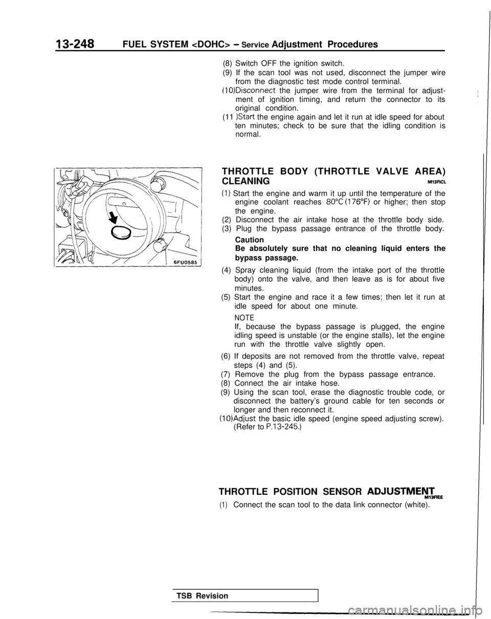
(2) Disconnect the air intake hose at the throttle body side.
(3) Plug the bypass passage entrance of the throttle body.
Caution
Be absolutely sure that no cleaning liquid enters the
bypass passage.
(4) Spray cleaning liquid (from the intake port of the throttle body) onto the valve, and then leave as is for about five
minutes.
(5) Start the engine and race it a few times; then let it run at
idle speed for about one minute.
NOTE
If, because the bypass passage is plugged, the engine
idling speed is unstable (or the engine stalls), let the engine
run with the throttle valve slightly open.
(6) If deposits are not removed from the throttle valve, repeat steps (4) and (5).
(7) Remove the plug from the bypass passage entrance.
(8) Connect the air intake hose.
(9) Using the scan tool, erase the diagnostic trouble code, or disconnect the battery’s ground cable for ten seconds or
longer and then reconnect it. (lO)Adjust
the basic idle speed (engine speed adjusting screw).
(Refer to
P.13-245.)
THROTTLE POSITION SENSOR ADJUSTMEyTmEE
(1)Connect the scan tool to the data link connector (white).
TSB Revision
Page 393 of 1273
FUEL SYSTEM
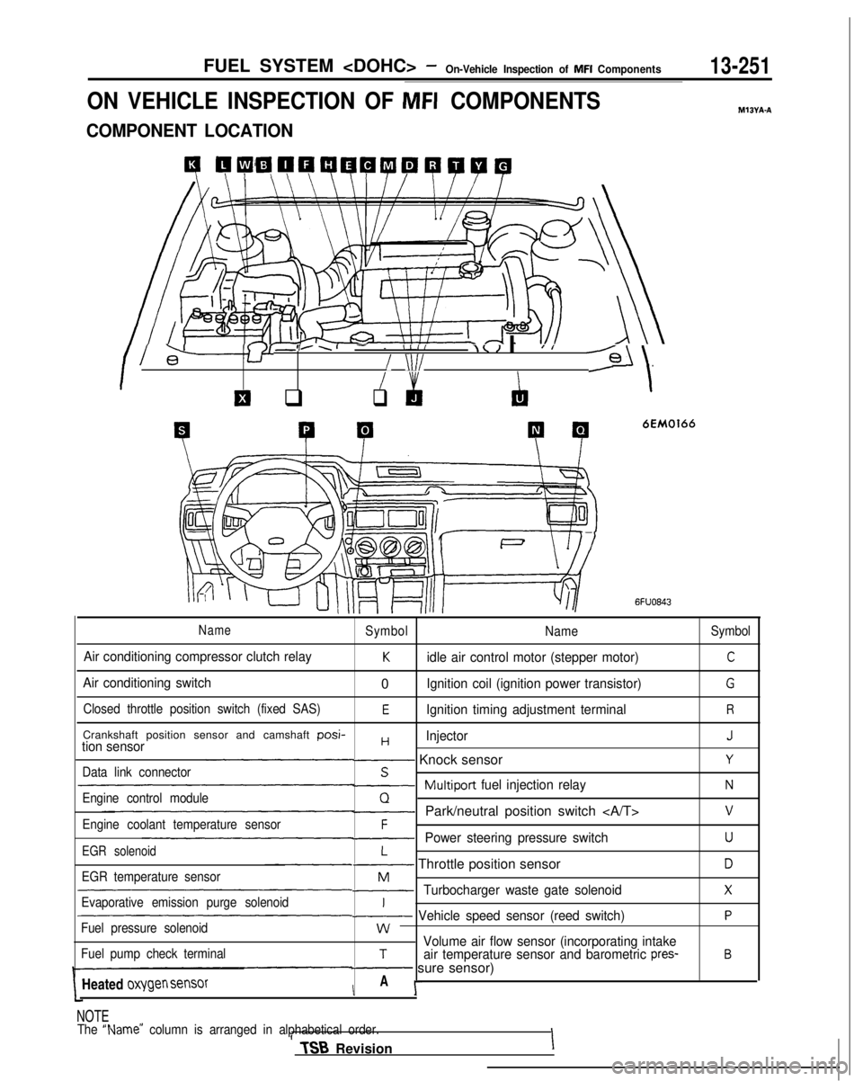
ON VEHICLE INSPECTION OF MFI COMPONENTS
COMPONENT LOCATION
4 QCiW41QQWPQWQ
I l-+-Y8’
-,..I- - IIII\< I IJ I
/ \lI/--Gl/
El q
I &
q
‘\
P P
6EM0166
MIBYA-A
6FUO843
NameSymbol
NameSymbol
Air conditioning compressor clutch relayKidle air control motor (stepper motor)C
Air conditioning switch0Ignition coil (ignition power transistor)G
Closed throttle position switch (fixed SAS)EIgnition timing adjustment terminalR
Crankshaft position sensor and camshaft posi-HInjectorJtion sensor- Knock sensorYData link connectorS~Multiport
fuel injection relayNEngine control moduleQ-Park/neutral position switch vEngine coolant temperature sensorF-Power steering pressure switchUEGR solenoidL- Throttle position sensorDEGR temperature sensorM-Turbocharger waste gate solenoidXEvaporative emission purge solenoidI~ Vehicle speed sensor (reed switch)PFuel pressure solenoidwVolume air flow sensor (incorporating intakeFuel pump check terminalTair temperature sensor and barometric pres-B- sure sensor)
Heated
oxygen sensorIA I-
NOTE
The “Name” column is arranged in alphabetical order.II TSB
RevisionI
Page 404 of 1273
13-262FUEL SYSTEM
INSPECTION
Using Scan tool
1 Data 12reading
L
Data displayInspection conditions
Sensor de-. Engine coolanttection airtemperature: 85-95°Cvolume (fre-(185-205°F)quency) .Lights, cooling fan, elec-trical accessories: OFF. Transaxle: neutral (PJTmodels: “P” range)
Engine condition
Idling
2,000 rpm
Racing
Standard value 25-50
Hz
60-90 Hz
Frequency increases as
racing rpm increases.
NOTEThe volume air flow sensor output frequency may be about 10% higher than\
indicated above when the vehicle is new
[driven approximately 500 km(300 miles) or less].
i
Regular waveform03AO203
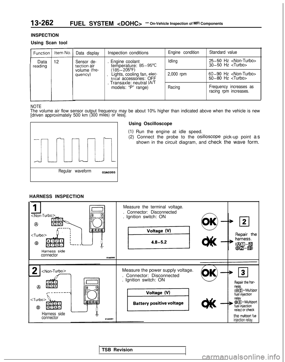
HARNESS INSPECTION Using Oscilloscope
(1) Run the engine at idle speed.
(2) Connect the probe to the osilloscope
pick-up point as
shown in the circuit diagram, and check the wave form.
Measure the terminal voltage.
. Connector: Disconnected
. Ignition switch: ON
connectorOlMaa
Measure the power supply voltage.
. Connector: Disconnected
. Ignition switch: ON
Harness side
connectorthe multiport fueinjection relay.
TSB Revision
Page 410 of 1273
13-26813-268FUEL SYSTEM
On-Vehicle Inspection of MFI Components
ENGINE COOLANT TEMPERATURE SENSOR
ENGINE COOLANT TEMPERATURE SENSORMl3YIABlMl3YIABl
Coolant temperature
Coolant temperature 1ez4sa
Coolant temperature
Coolant temperature
16210081621008
t+arness s,de C
ompone
nt side
Engine coolant temperature sensorIconnector
connectori- ,
Jr
Engine
control module
Ih5v
6FU1239
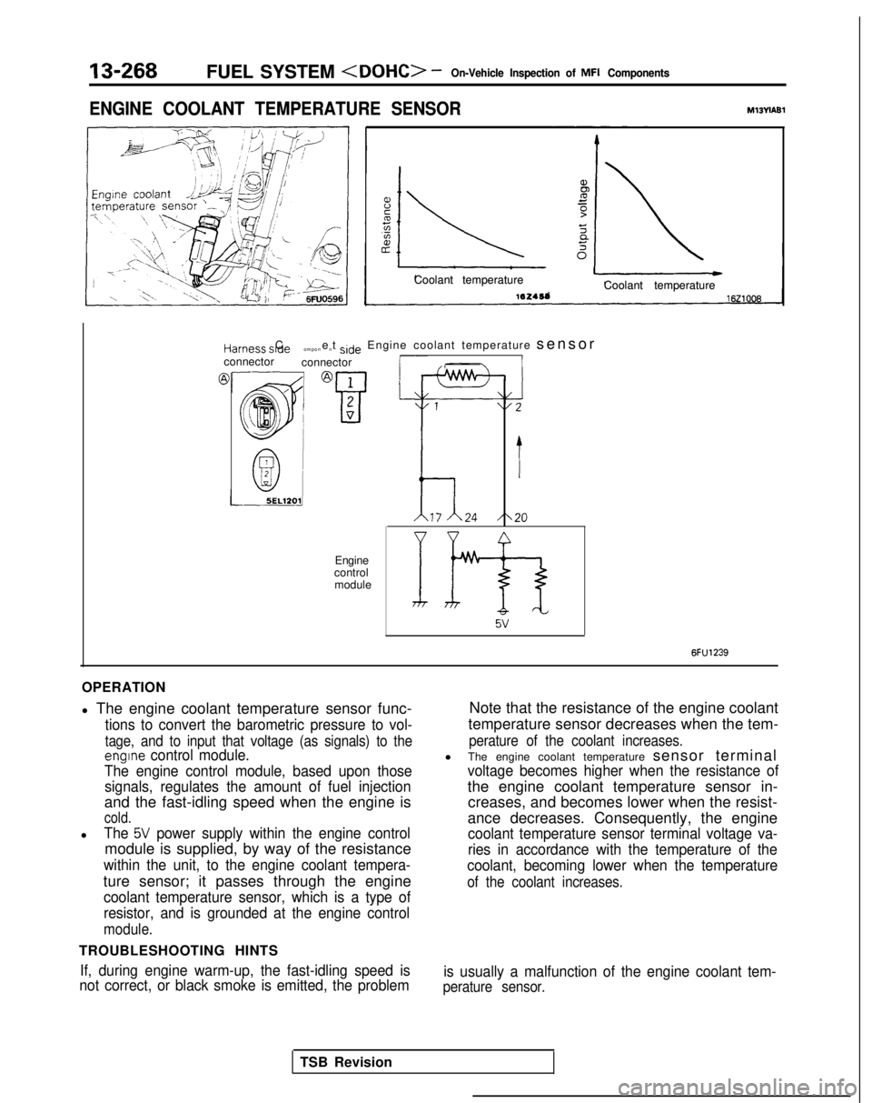
OPERATION
l The engine coolant temperature sensor func-
tions to convert the barometric pressure to vol-
tage, and to input that voltage (as signals) to the
engine control module.
The engine control module, based upon those signals, regulates the amount of fuel injection
and the fast-idling speed when the engine is
cold.
lThe 5V power supply within the engine control
module is supplied, by way of the resistance
within the unit, to the engine coolant tempera-
ture sensor; it passes through the engine
coolant temperature sensor, which is a type of
resistor, and is grounded at the engine control
module.
TROUBLESHOOTING HINTS
If, during engine warm-up, the fast-idling speed is
not correct, or black smoke is emitted, the problem
Note that the resistance of the engine coolant
temperature sensor decreases when the tem-
perature of the coolant increases.
l The engine coolant temperature sensor terminal
voltage becomes higher when the resistance of
the engine coolant temperature sensor in-
creases, and becomes lower when the resist-
ance decreases. Consequently, the engine
coolant temperature sensor terminal voltage va-
ries in accordance with the temperature of the
coolant, becoming lower when the temperature
of the coolant increases.
is usually a malfunction of the engine coolant tem-
perature sensor.
TSB Revision
Page 411 of 1273
1 V-L “IVILI.,. ““I ,“Ivn-ven,c,e lnsprcrlorl 91
l”lb-l b”mp”nerlrrI” L””
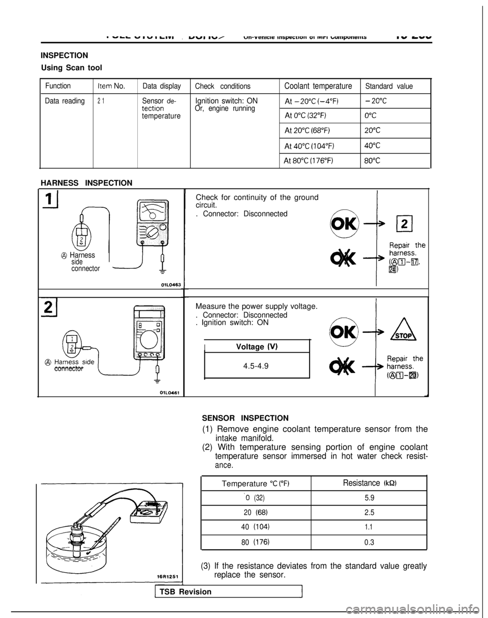
INSPECTION
Using Scan tool
FunctionItem No.Data display Check conditionsCoolant temperatureStandard value
Data reading
2 1Sensor de-Ignition switch: ONAt -20°C
(-4°F)- 20°CtectionOr, engine running
temperatureAt 0°C (32°F)0°C
At 20°C (68°F)20°C
At 40°C (104°F)40°C
At 80°C (176°F)80°C
HARNESS INSPECTION
@ Harnesssideconnector
OlL0463
connector
OlL0461
Check for continuity of the groundcircuit.
. Connector: Disconnected
Measure the power supply voltage.
. Connector: Disconnected. Ignition switch: ON
IVoltage (V)
4.5-4.9
SENSOR INSPECTION (1) Remove engine coolant temperature sensor from the
intake manifold.
(2) With temperature sensing portion of engine coolant
temperature sensor immersed in hot water check resist-
ance.
Temperature “C V’F)Resistance (kQ)
‘0(32)5.9
20(68)2.5
40
(104)1.1
80(176)0.3
(3) If the resistance deviates from the standard value greatly replace the sensor.
TSB Revision
Page 412 of 1273
13-270FUEL SYSTEM
INSTALLATION
(1) Apply sealant 3M NUT locking No.4171 or
equivalent to threaded portion.
(2) Install engine coolant temperature sensor and
tighten it to specified torque. Sensor tightening
torque:
20-40 Nm (15-29 ft.lbs.1
(3) Fasten harness connectors securely.
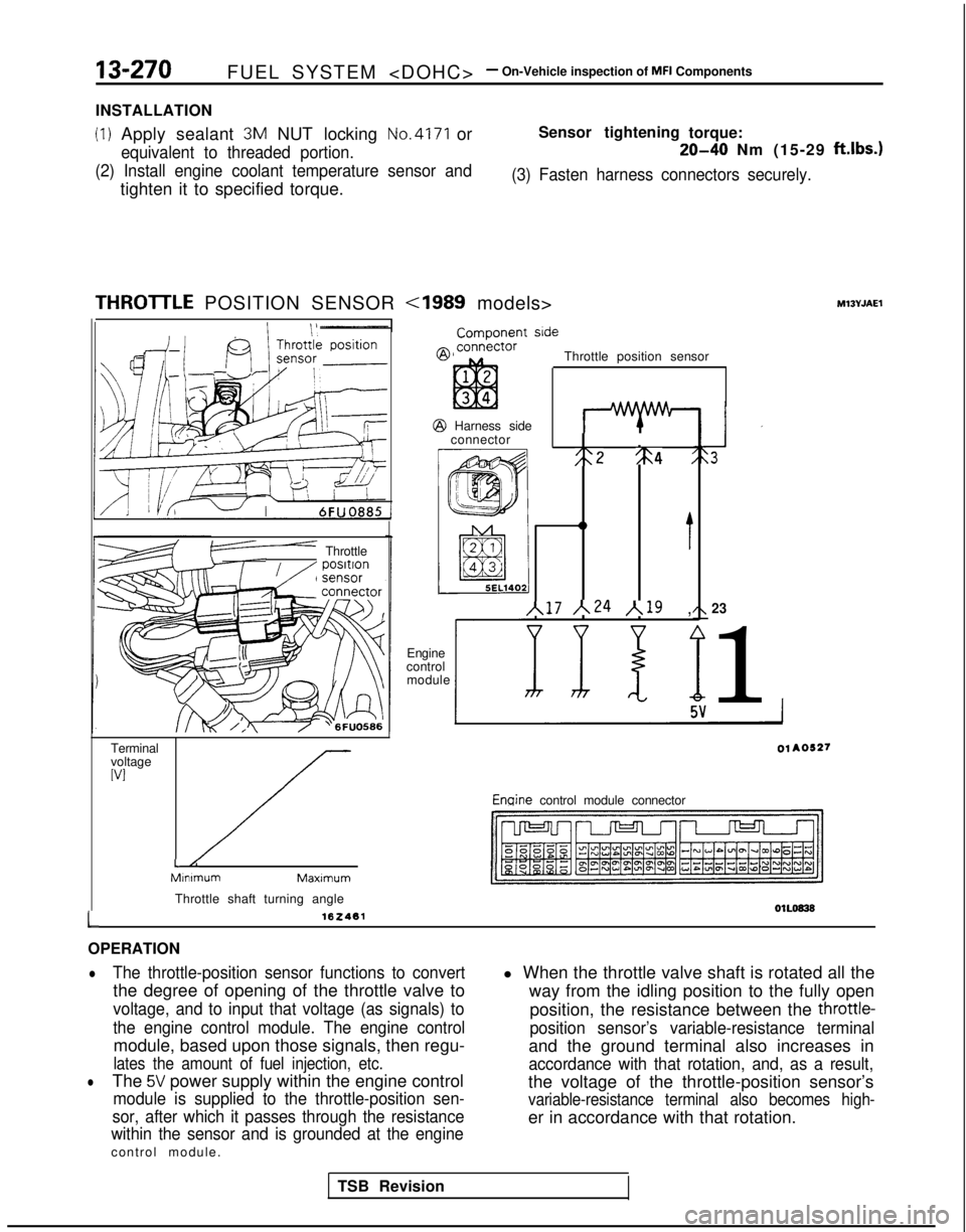
THROlTLE POSITION SENSOR
F” Throttle
Terminal
voltage
WI
//-L/:MInimumMaxlmum
Throttle shaft turning angle
162461
ComDonent side
Throttle position sensor @
Harness side
connector
I
;:2 %4 :
0
t
~17 ~24 /,19 ,
Engine
control module23
1 Enqine
control module connector
01L0838L
OPERATION
lThe throttle-position sensor functions to convert
the degree of opening of the throttle valve to
voltage, and to input that voltage (as signals) to
the engine control module. The engine control
module, based upon those signals, then regu-
lates the amount of fuel injection, etc.
lThe 5V power supply within the engine control
module is supplied to the throttle-position sen-
sor, after which it passes through the resistance
within the sensor and is grounded at the engine
control module. l When the throttle valve shaft is rotated all the
way from the idling position to the fully open
position, the resistance between the
throttle-
position sensor’s variable-resistance terminal
and the ground terminal also increases in
accordance with that rotation, and, as a result,
the voltage of the throttle-position sensor’s
variable-resistance terminal also becomes high-
er in accordance with that rotation.
TSB Revision
Page 423 of 1273

FUEL SYSTEM
OPERATION
l
The crankshaft position sensor functions to de-
tect the crank angle (position) of each cylinder,
and to convert those data to pulse signals,
which are then input to the engine control mod-
ule. The engine control module, based upon
those signals, calculates the engine rpm, and
also regulates the fuel injection timing and the
ignition timing.
TROUBLESHOOTING HINTS
Hint 1:
If an impact is suddenly felt during driving or the en-
gine suddenly stalls during idling, try shaking the
crankshaft position sensor during idling.
If the engine stalls, the cause may be presumed to
be improper or incomplete contact of the crank-
shaft position sensor’s connector.
Hint 2:
If the crankshaft position sensor output rpm is 0
rpm during cranking when the engine cannot be
started, the cause may be presumed to be a mal-
function of the crankshaft position sensor or a bro-
ken timing belt.
Hint 3:
If the indicated value of the crankshaft position sen-
sor output rpm is 0 rpm during cranking when the
engine cannot be started, the cause may be pre-
INSPECTION
Using Scan tool l
The power for the crankshaft position sensor is
supplied from the ignition switch-IG
and is
grounded to the vehicle body. The crankshaft
position sensor, by intermitting the flow (to
ground) of the 5V voltage applied from the en-
gine control module, produces pulse signals.
sumed to be a failure of the ignition coil’s primary
current to intermittently pulse correctly, so a mal-
function of the ignition system circuitry, the ignition
coil and/or the power transistor is the probable
cause. Hint 4:
If idling is possible even though the crankshaft posi-
tion sensor indicated rpm is a deviation from the
standard value, the cause is usually a malfunction of
something other than the crankshaft position sen-
sor.
Examples:
(1) Malfunction of the coolant-temperature sensor.
(2) Malfunction of the idle air control motor.
(3) Improper adjustment of the standard idling
speed.
Inspection conditions
Description Normal condition
. Engine: CrankingCompare crankingBoth agree.. Tachometer connectionrpm and scan tool(Check intermittent flow ofindicated rpm.ignition coil primary current
by tachometer.)
burn No. / ~i~~~~,,Inspection conditions
At 40°C (104°F)
At 80°C (176°F)
1 ,OOO- 1,250 rpm
650-850 rpm
TSB Revision
I
Page 432 of 1273
13-290FUEL SYSTEM
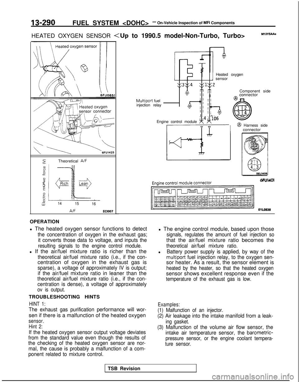
HEATED OXYGEN SENSOR
sensor connector
2Theoretical A/F
8.5
P.-
5
E
Pt;2Lw1415 16
AJFEC1007
Component side
Heated oxygen
. sensor
y3y4 $1y2
nri rlT” IIMultiport fuel
injection relayd; II
TII :‘aII Il. 7
Engine control module x4H106@ Harness side
connector
OlLoB38
OPERATION
l The heated oxygen sensor functions to detect
the concentration of oxygen in the exhaust gas;
it converts those data to voltage, and inputs the
resulting signals to the engine control module.
l If the air/fuel mixture ratio is richer than the
theoretical air/fuel mixture ratio (i.e., if the con-
centration of oxygen in the exhaust gas is
sparse), a voltage of approximately IV is output;
if the air/fuel mixture ratio in leaner than the
theoretical air/fuel mixture ratio (i.e., if the con-centration is dense), a voltage of approximately
ov is output.
TROUBLESHOOTING HINTS
HINT 1:
The exhaust gas purification performance will wor-
sen if there is a malfunction of the heated oxygen
sensor.
Hint 2:
If the heated oxygen sensor output voltage deviates
from the standard value even though the results of
the checking of the heated oxygen sensor are nor-
mal, the cause is probably a malfunction of a com-
ponent related to mixture control.
l The engine control module, based upon those
signals, regulates the amount of fuel injection so
that the air/fuel mixture ratio becomes the
theoretical air/fuel mixture ratio.
lBattery power supply is applied, by way of the
multiport fuel injection relay, to the oxygen sen-
sor heater. As a result, the sensor element is
heated by the heater, so that the heated oxygen
sensor shows excellent response even if the
temperature of the exhaust gas is low.
Examples:
(1) Malfunction of an injector.
(2) Air leakage into the intake manifold from a leak-
ing gasket.
(3) Malfunction of the volume air flow sensor, the intake air temperature sensor, the
barometric-
pressure sensor, or the engine coolant tempera-
ture sensor.
TSB Revision