1989 MITSUBISHI GALANT engine coolant
[x] Cancel search: engine coolantPage 434 of 1273
13-292FUEL SYSTEM
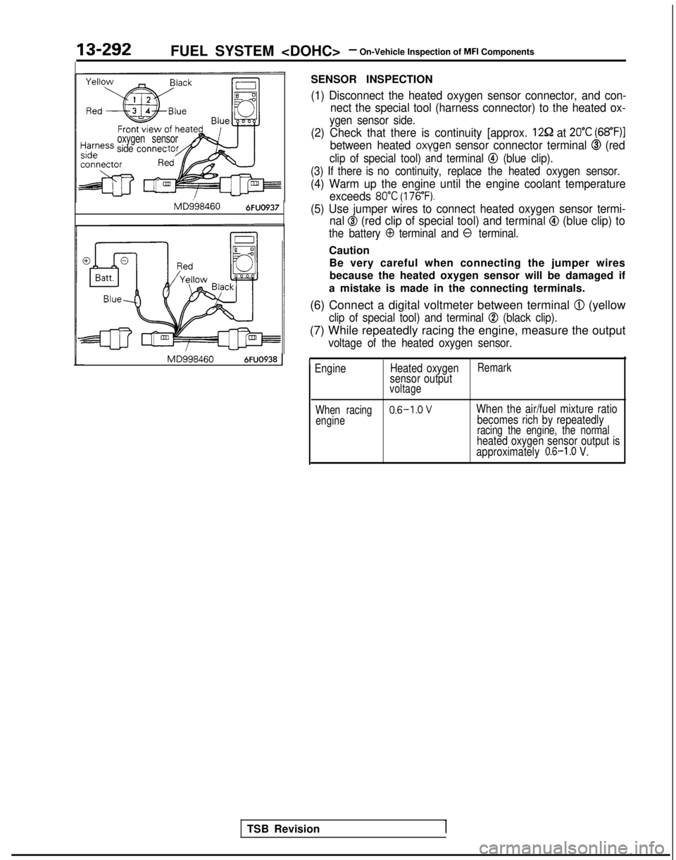
Harnessoxygen sensorside connec
MD9984606FUO937
MD9984606FUO938
SENSOR INSPECTION
(1) Disconnect the heated oxygen sensor connector, and con-nect the special tool (harness connector) to the heated ox-
ygen sensor side.
(2) Check that there is continuity [approx. 1252 at 20°C (68”F)]
between heated oxygen sensor connector terminal @ (red
clip of special tool) and terminal @ (blue clip).
(3) If there is no continuity, replace the heated oxygen sensor.
(4) Warm up the engine until the engine coolant temperature
exceeds
80°C (176°F).
(5) Use jumper wires to connect heated oxygen sensor termi-nal
@ (red clip of special tool) and terminal @I (blue clip) to
the battery 0 terminal and 0 terminal.
Caution
Be very careful when connecting the jumper wiresbecause the heated oxygen sensor will be damaged if
a mistake is made in the connecting terminals.
(6) Connect a digital voltmeter between terminal
@ (yellow
clip of special tool) and terminal @ (black clip).
(7) While repeatedly racing the engine, measure the output
voltage of the heated oxygen sensor.
’ Engine Heated oxygenRemarksensor outputvoltage
When racing
0.6-1.0 VWhen the air/fuel mixture ratio
enginebecomes rich by repeatedlyracing the engine, the normalheated oxygen sensor output is
approximately 0.6-I .O V.
TSB Revision1
Page 438 of 1273
13-296FUEL SYSTEM
Inspection
of
MFI
Components
INSPECTION
Using Scan tool
Function Item No. Data displayInspection conditionsEngine coolant temperature Standard value1
Data 41;ctJ$onEngine crankingAt 0°C (32”F)*2Approx. 17 ms
readingApprox. 40 ms
At 20°C (68°F)Approx. 38 ms
Approx. 19 ms
At 80°C (176°F)Approx. 9 ms
Approx. 4.5 ms
Function
Datareading
3TE Item No.
41
Data display
$ctX$on
Inspection conditionsEngine condition
Standard value
. Engine coolant tempera-Idling2.4-3.2 ms
ture:1.6-2.6 ms
(185-205°F)
. Lights, cooling fan, electric- 2,000 rpm1.9-2.9
ms
al accessories: OFF1.4-2.2 ms
+l:The injector activation time indicates the time under the following cond\
itions: a power source voltage of 11V and acranking rpm of 250 rpm or less.*2: Simultaneous injection at four cylinders when engine coolant temperatur\
e is 0°C (32°F).*3: The injector activation time may be about 10% longer than indicated abo\
ve when the vehicle is new [driven
approximately 500 km (300 miles) or less].
Function Item No.Description Inspection conditionsNormal indication
Actuator test 01No. 1 injector is shut off.
Engine: idling after warmThe idling condition
02No. 2 injector is shut off.?!hut off the injectors inchanges more.
(Either becomes more un-
03
No. 3 injector is shut off.
04
No.4 injector is shut off.
sequence during after
engine warm-up, check
the idling condition.) stable, or engine stalls.)
,d&- A: InjectorNormal wavetormdrive time
HARNESS INSPECTION
@ Harness sideconnector
I
L
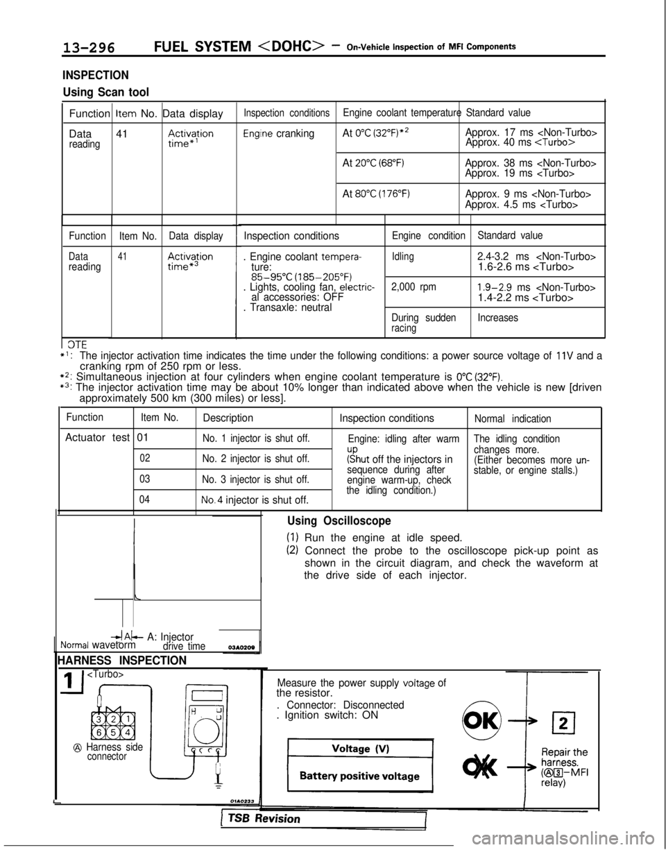
Using Oscilloscope
(1) Run the engine at idle speed.
(2) Connect the probe to the oscilloscope pick-up point as
shown in the circuit diagram, and check the waveform at
the drive side of each injector.
Measure the power supply voltage ofthe resistor.
. Connector: Disconnected. Ignition switch: ON
1 TSB hevision
Page 441 of 1273
FUEL SYSTEM
MFI Components13-299
OPERATION
l The amount of air taken in during idling is
regulated by the opening and closing of the
servo valve located in the air passage that
bypasses the throttle valve.
l The servo valve is opened or closed by the
activation of the stepper motor (incorporated
within the idle air control motor) in the forward
or reverse direction.
TROUBLESHOOTING HINTS
Hint 1: If the number of stepper motor steps increases to
IOO- 120 steps or decreases
to 0 step, the cause may be presumed to be a malfunction of the stepper motor or
damaged or disconnected wiring of the
harness.
Hint 2: If the number of stepper motor steps
deviates from the standard value even
though the results of the checking of the
harness of the idle air control motor and of
the comoonent
itself indicate no abnormal
condition, the cause may be presumed to be one of the following.
INSPECTION
Using Scan tool
lBattery power supply is supplied, by way of the
multiport fuel injection relay, to the coil of the
stepper motor. The engine control module
switches ON the power transistors (located
within the engine control module) in sequential
order, and, when current flows to the stepper motor coil, the stepper motor is activated in the
forward or reverse direction.
(1) Improper adjustment of the standard
idling speed.
(2) Deposits adhered to the throttle valve.
(3) Leakage of air into the intake manifold
from a gasket gap, etc.
(4) Incomplete close contact of the EGRvalve seat.
(5) Incomplete combustion within the
cylinder.
(Malfunction of the spark plugs, the
ignition coil, the iniectors,
the
com- pression
pressure, etc.)
FunctionItem No.Data display Check conditions Load conditionsStandard value
Data reading 45Steppermotor steps. Engine coolant tempera-
. Air conditioning
4-14Step
ture:switch: OFF
(185-205°F)
. Lights, electrical cooling
:$b::pfan and accessories: OFF
. Transaxle: neutral
. Closed throttle switch: ON
- Air conditioning 20-60 Step
switch: ON
(The compressor clutchshould be activated when
the air conditioning switch;J-;;o~P
is switched ON.)* Engine: idling
1;:!,1;:!,
/!-I\/!-I\
f$&$:”f$&$:”
! ,‘,! ,‘,
4);4);
;jj\(Q(j!jGZ-);jj\(Q(j!jGZ-)
lili
q#Q~Hq#Q~HF]F]
ii 2 L J 2 L ~ -0SClllO 4ii 2 L J 2 L ~ -0SClllO 4
NOTE
When the vehicle is new (driven approximately 500 km (300 miles) or l\
ess) the number of steps may be about
30 steps greater than the standard value indicated above.
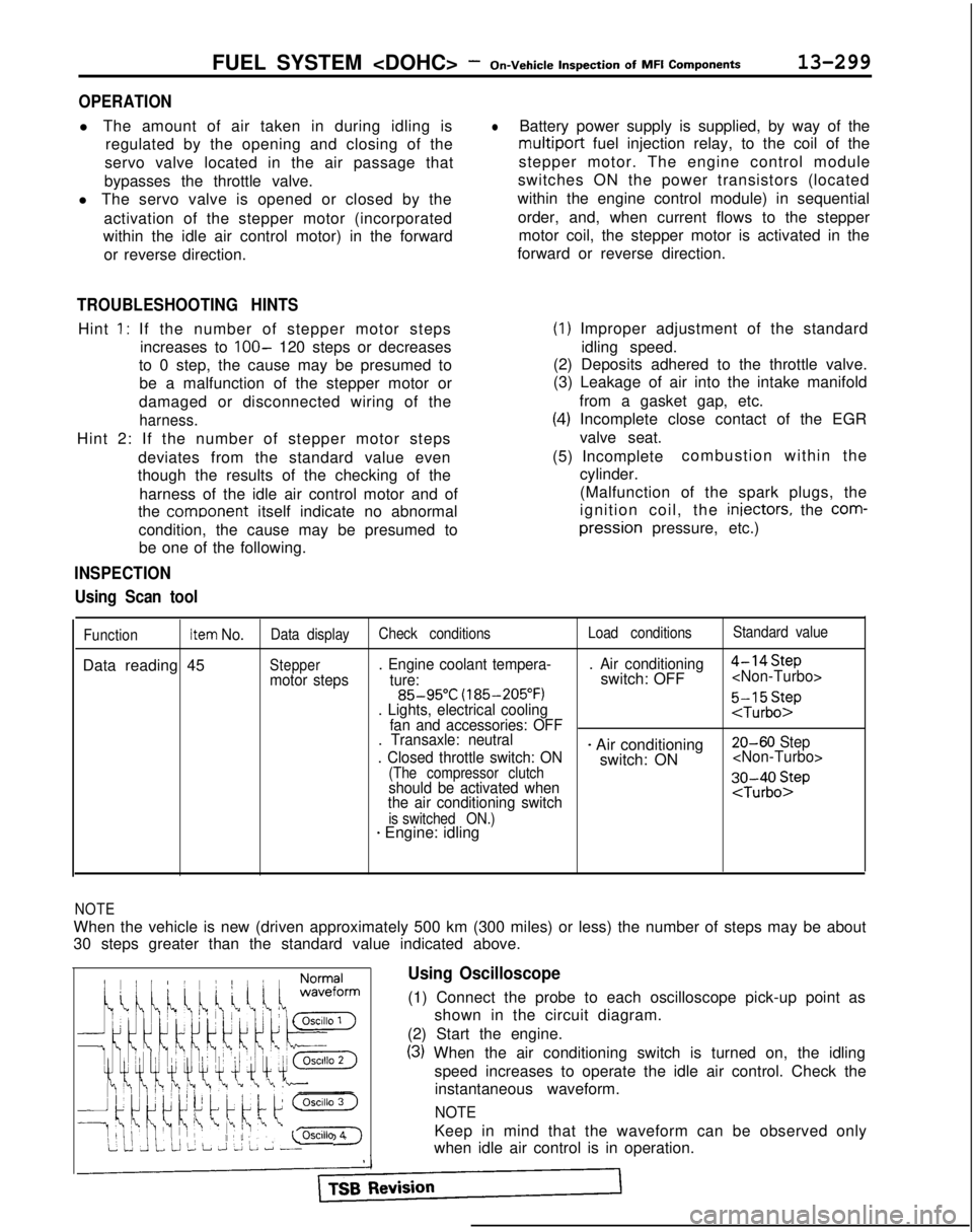
Using Oscilloscope
(1) Connect the probe to each oscilloscope pick-up point as
shown in the circuit diagram.
(2) Start the engine.
(3) When the air conditioning switch is turned on, the idling speed increases to operate the idle air control. Check theinstantaneous waveform.
NOTE
Keep in mind that the waveform can be observed only
when idle air control is in operation.
Page 450 of 1273
13-308FUEL SYSTEM
of
MFI
Components
OPERATION
l
The fuel pressure solenoid is an ON-OFF type of
solenoid valve and changes pressure fed into
the fuel pressure regulator to intake manifold
pressure and barometric pressure.
l Battery power is supplied to the fuel pressure
solenoid via the multiport
fuel injection relay.
When the engine control module turns on the
power transistor in the unit, current flows in the
coil and barometric pressure is fed to the fuel pressure regulator.
INSPECTION
Using Scan tool
0 If engine coolant temperature (approximatel
y
95°C (203°F) or more) and also air intake
temperature (approximately
50°C (122°F) or
more) are high when the engine is started, fuel
pressure is controlled in order to maintain
pressure at approximately 260
kPa (37 psi)
immediately after starting and then, after a lapse
of approximately 30 seconds to 2 minutes, to lower it to approximately 190
kPa (27 psi).
Function Item No.
Actuator test 09
DescriptionInspection conditionsNormal condition
$$;;i;;;alve switched fromIgnition switch: ONOperating sound is
heard when driven.
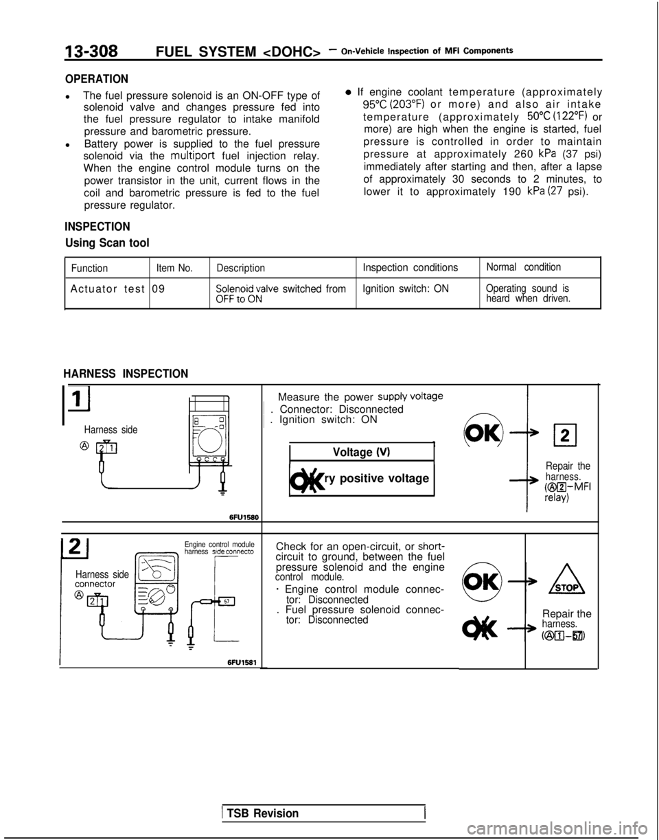
HARNESS INSPECTION
Harness side
Measure the power supply VokW 1
. Connector: Disconnected 1
. Ignition switch: ON
Voltage 04
1 Battery positive voltage 1t)lt<
02
Repair theharness.
@I4,MFI
Engine control module
harness side connecto
Harness side
Check for an open-circuit, or shot-t-circuit to ground, between the fuel
pressure solenoid and the engine
control module.
- Engine control module connec-tor: Disconnected. Fuel pressure solenoid connec-tor: DisconnectedRepair theharness.
h25xwzl21,
1 TSB Revision
Page 457 of 1273
FUEL SYSTEM
On-Vehicle
Inwection of MFI
ComDonents13-315
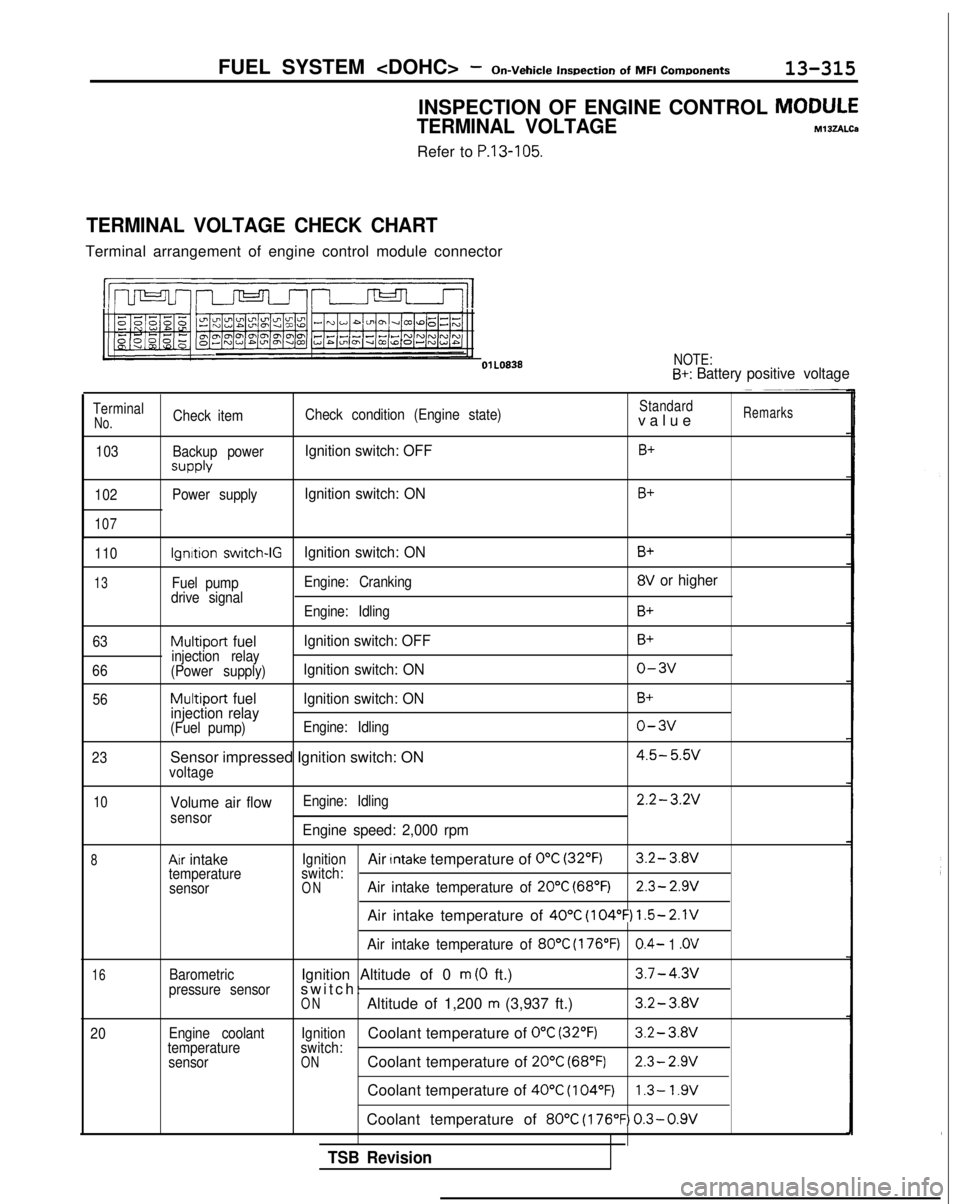
INSPECTION OF ENGINE CONTROL MODULE
TERMINAL VOLTAGEM13zALCa
Refer to P.13-105.
TERMINAL VOLTAGE CHECK CHART
Terminal arrangement of engine control module connector
l!m n-J-J-l-II
NOTE:B+: Battery
positive voltage
TerminalCheck item Check condition (Engine state)Standardvalu
e
Remarks
No.
103
102
107
Backup power
SUPPlY
Power supply
Ignition switch: OFFB+
Ignition switch: ONB+
110
13
63
66 56
23
Ignition switch-IGIgnition switch: ON
Fuel pump Engine: Cranking
drive signal Engine: Idling
Multiport fuel Ignition switch: OFFinjection relay
(Power supply)Ignition switch: ON
Multiport fuel Ignition switch: ON
injection relay
(Fuel pump) Engine: Idling
Sensor impressed Ignition switch: ONvoltage
B+
8V or higher
B+
B+
o-3v
B+
o-3v
4.5- 5.w
10
8
16
20
Volume air flowsensor
Ax intaketemperature
sensor
Barometric
pressure sensor
Engine coolant
temperature sensor Engine: Idling
2.2-3.2V
Engine speed: 2,000 rpm
IgnitionAir Intake temperature of 0°C (32°F)3.2- 3.8V
switch:
ONAir intake temperature of 20°C (68°F)2.3- 2.9V
Air intake temperature of 40°C (104°F) 1.5-2.1V
Air intake temperature of 80°C (176°F)0.4- 1 .OV
Ignition Altitude of 0 m (0 ft.)3.7-4.3v
switch
:
ONAltitude of 1,200 m (3,937 ft.)3.2-3.8V
IgnitionCoolant temperature of 0°C (32’F)3.2-
3.Wswitch:ONCoolant temperature of 20°C (68°F)2.3- 2.9V
Coolant temperature of 40°C (104°F)1.3- 1.9V
Coolant temperature of 80°C (176°F) 0.3-0.9V
TSB Revision
Page 553 of 1273

14-1
COOLING
ENGINE COOLANT TEMPERATURE GAUGE
UNIT, ENGINE COOLANT
TEMPERATURE SENSOR AND ENGINE
COOLANT TEMPERATURE
SWITCH.............
31
RADIATOR ....................................................... 9
RADIATOR FAN MOTOR ASSEMBLY ..........
12
SERVICE ADJUSTMENT PROCEDURES..
.....
8
Engine Coolant Concentration Test .............
8
Engine Coolant LeakCheck
........................8
Engine Coolant
Replacement .......................
8
Radiator Cap Pressure Test .........................
8
SPECIAL TOOL................................................5
SPECIFICATIONS .............................................
2
General Specifications ..................................
2
Lubricant
....................................................... 4
CONTENTS
IM14AA-
Sealant. . . . . . . . . . . . . ..__...........’ . . . . . . . . . . . . . \
. . . . . .._.........4
ServiceSpecifications . . . . .. . . . . . . . . . . . . . . . . . . . . . . . . . . . .2
Torque
Specifications. . . . . . . . . . . . . . . . . . . . . . . . . . . . . . . . . . .3
THERMOSTAT. . . . . . . . . . . . . . . . . . . . . . . . . . . . . . . . . . . . \
. . . . . . . . . . . . .13
TROUBLESHOOTING. . . . . . . . . . . . . . . . . . . . . . . . . . . . . . . . . . . . \
. .5
No rise in temperature
Overheat
WATER HOSE AND WATER PIPE
. . . . . . . . . . . . . . . . . . . . . . . . . . . . . . . . . . .26
WATER HOSE AND WATER PIPE
WATER HOSE AND WATER PIPE
. . . . . . . . . . . . . . . . . . . . .
. . . . . . . . . . . . . . . . . . . . . . . . . . . . . ..a.....23
WATER PUMP
WATER PUMP
. . . . . . . . . . . . . . . . . . . . . . . . . . . . . . .15
Page 554 of 1273
14-2
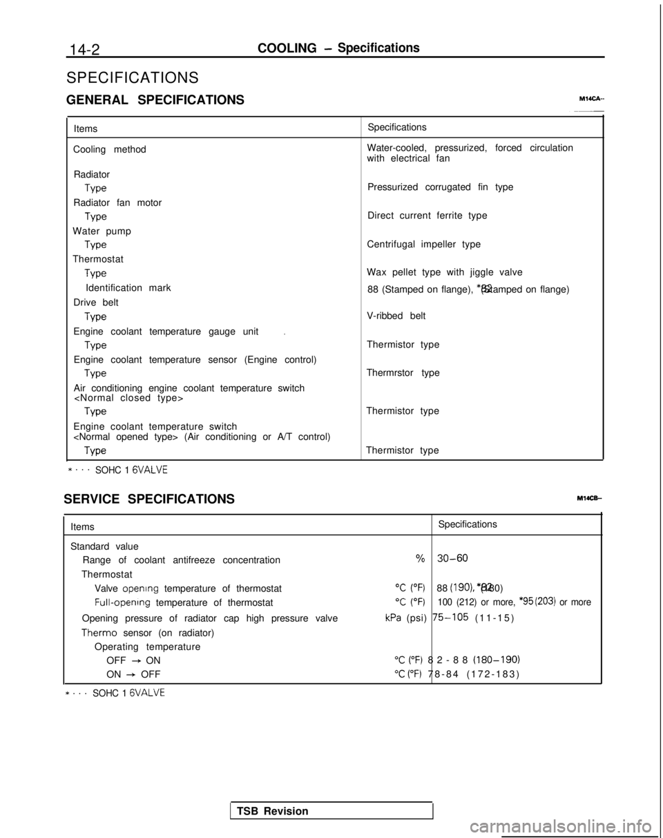
COOLING- Specifications
SPECIFICATIONS
GENERAL SPECIFICATIONS
MlICA-
Items
Cooling method Specifications
Water-cooled, pressurized, forced circulation
with electrical fan
Radiator Type
Radiator fan motor Type
Water pump Type
Thermostat Type
Identification mark
Drive belt Type
.Engine coolant temperature gauge unit
Type
Engine coolant temperature sensor (Engine control) Type
Air conditioning engine coolant temperature switch
Engine coolant temperature switch
* . . .SOHC 1 GVALVE
Pressurized corrugated fin type
Direct current ferrite type
Centrifugal impeller type
Wax pellet type with jiggle valve 88 (Stamped on flange), *82 (Stamped on flange)
V-ribbed belt
Thermistor type
Thermrstor type
Thermistor type
Thermistor type
SERVICE SPECIFICATIONS
MlOCB-
Items
Standard value Range of coolant antifreeze concentration
Thermostat Valve opening
temperature of thermostat Full-opening
temperature of thermostat
Opening pressure of radiator cap high pressure valve Therm0
sensor (on radiator)
Operating temperature OFF
+ ON
ON
+ OFF
* . . .SOHC 1 GVALVE
Specifications
% 30-60
“C (“F)88 (IgO), *82 (180)
T (OF)100 (212) or more, *95 (203) or more
kPa (psi) 75-105 (11-15
)
“C (“F) 82-88 (180-190)
“C (“F) 78-84 (172-183
)
TSB Revision
Page 555 of 1273

COOLING- Specifications14-3
Items Specifications
Engine coolant temperature gauge unit ResistanceAt
70°C (158°F)n 104f13.5
Engine coolant temperature sensor (Engine control) ResistanceAt
20°C (68°F)kQ 2.45 f 0.24
At 80°C (176°F)Q 296+32
Air conditioning engine coolant temperature switch
ON
+ OFF operating temperature“C (“F) 112-118 (234-244
)
Engine coolant temperature switch
(Air conditioning or A/T control)
OFF
+ ON operating temperature“C (“F) 100-104 (212-219
)
Limit
Opening pressure of radiator cap high pressure valvekPa (psi) 65 (9.2)
TORQUE SPECIFICATIONS
MWCG-
ItemsNm ft.lbs.
Radiator upper insulator 9-14
7-10
Reserve tank, bracket installation bolt9-1
4
7-10
Thermosensor to radiator35
25
Automatic transaxle oil coole: hose cramp 4-
6
3-4
Automatic transaxle oil cooler hose mounting bolt 3-5
2-4
Water outlet fitting bolts
17-2012-14
Water inlet fitting bolts
IO-157-10
Engine mount insulator nut (large)60-8043-58
Engine mount insulator nut (small)
\ 30-4022-29
Engine mount bracket to engine
50-6536-47
Bracket between engine mount bracket and engine 17-26
12-19
Water pump installation bolt Bolt head mark “4T”
12-15
9-l 1
Bolt head mark “7T”20-2714-20
dater pump pulley bolt8-106-
7
Jamper pulley, crankshaft pulley20-3014-22
Timing belt front upper cover installation bolt
IO-127-
9
Timing belt front lower cover installation bolt
IO-127-
9
Crankshaft
sprocket installation bolt
110-13080-94
Timing belt B tensioner 15-2211-16
Tension pulley bracket for air conditioning
23-2717-20
Automatic tensioner installation bolt20-2714-20
Tensioner pulley installation bolt43-5531-40
Oil level gauge 12-159-l 1
Front exhaust pipe to exhaust manifold
Front exhaust pipe bracket
30-4022-29
Exhaust manifold cover (A), (B)
9-11
Heat protector
TSB Revision