Page 583 of 1273
COOLING -Engine Coolant Temperature Gauge Unit, Engine CoolantTemoerature Sensor and Engine Coolant Temperature Switch14-31
ENGINE COOLANT TEMPERATURE GAUGE UNIT, ENGINE COOLANT
TEMPERATURE SENSOR AND ENGINE COOLANT TEMPERATURE
SWITCHM14oE-
REMOVAL AND INSTALLATION
30-40
Nm/
gine Coolantlo-14 Nm(Refer to GROUP 00-Maintenance8-10 ft.lbs.Service.)
/ I r lcoolo
Sealant: 3M ATD Part No.8660or equivalent04A0118
< 1993 models>
10 12 Nrny~~~~~7-9 ft.lbs. 2
1. Engine coolant temperature gauge unit
2. Engine coolant temperature sensor
(Engine control)3. Air conditioning engine coolanttemperature switch
type>4. Engine coolant temperature switch, . (Air condltloning
or A/T control)
Sealant: 3M Nut locking PartNo.4171 or equivalent
TSB Revision
Page 584 of 1273

14-32COOLING -Engine Coolant Temperature Gauge Unit, Engine Coolant
Temperature Sensor and Engine Coolant Temperature Switch
/
Sensor
J
046003
3
04GOO32
9FUO156
---
--I ‘Oi
l
QQQQQQ2cmn99
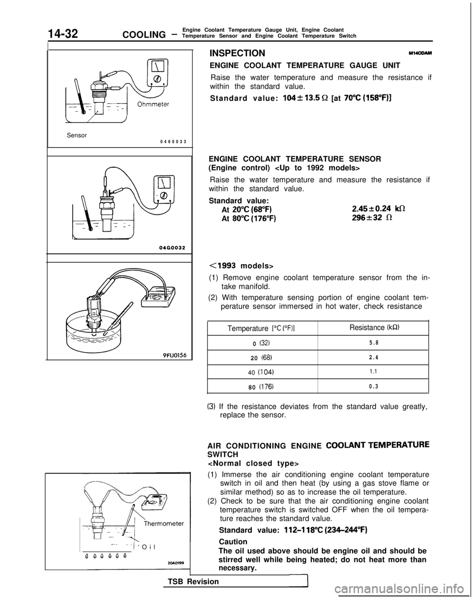
INSPECTIONM14OOAM
ENGINE COOLANT TEMPERATURE GAUGE UNIT
Raise the water temperature and measure the resistance if
within the standard value.
Standard value:
104k13.5 Q [at 70°C (158”F)]
ENGINE COOLANT TEMPERATURE SENSOR
(Engine control)
Raise the water temperature and measure the resistance if
within the standard value.
Standard value:
At
20°C (68°F)
At 80°C (176°F) 2.4520.24
klR
296232 R
<1993 models>
(1) Remove engine coolant temperature sensor from the in- take manifold.
(2) With temperature sensing portion of engine coolant tem- perature sensor immersed in hot water, check resistance
Temperature 1°C (OF)1Resistance (kR)
0 (32)5.8
20 (68)2.4
40
(I
04)1.1
80 (176)0.3
(3) If the resistance deviates from the standard value greatly,
replace the sensor.
AIR CONDITIONING ENGINE
COOLANT TEMPERATURE
SWITCH
(1) Immerse the air conditioning engine coolant temperature switch in oil and then heat (by using a gas stove flame or
similar method) so as to increase the oil temperature.
(2) Check to be sure that the air conditioning engine coolant temperature switch is switched OFF when the oil tempera-ture reaches the standard value.
Standard value:
112-l 18°C (234-244°F)
Caution
The oil used above should be engine oil and should be
stirred well while being heated; do not heat more than
necessary.
TSB Revision
Page 585 of 1273
COOLING -Engine Coolant Temperature Gauge Unit, Engine Coolant
Temperature Sensor and Engine Coolant Temperature Switch14-33
20R0586
ENGINE COOLANT TEMPERATURE SWITCH
(Air conditioning or A/T control)
(1) Remove the engine coolant temperature switch from the
water outlet fitting.
(2) immerse the engine coolant temperature switch in oil and heat by a gas stove or similar method so as to increase the
oil temperature.
(3) Check to be sure that the engine coolant temperature switch is switched ON when the oil temperature reaches
the standard value.
Standard value:
lOO-104% (212-219°F)
CautionUse engine oil for this test; stir it well while heating,
and do not heat more than necessary.
TSB Revision
1
Page 600 of 1273
15-14INTAKE AND EXHAUST -Intake Manifold
INTAKE MANIFOLD
{EMOVAL
AND INSTALLATION
4-6 Nm
Y “1 ~/c 3-4 ft.‘bs.At
4-6 ‘Nm
3-4 ft.lbs.
Removal steps
I. Air intake hose2. Connection for accelerator cable+e l +3. Connection for radiator upper hose4. Connection for water by-pass hose5. Water hose
6. Connection for heater hose
7. Connection for brake booster vacuum hose
8. Connection for fuel high pressure hose9. O-ring
10. Connection for fuel return hose
II. Connection for vacuum hoses12. Vacuum pipe13. PCV hose14. Connection for control harness
MlSMA-A
4-6 N
m
3-4
ft.lbs.OlA0647
Pre-removal Operationl Draining of Engine Coolant
(Refer to GROUP 00-MaintenanceService.)
Post-installation Operationl Filling of Engine Coolant(Refer to GROUP 00-MaintenanceService.)
l Adjustment of Accelerator Cable (Refer to GROUP
13-Engine Con-
trol.)
l inspection of Fuel Pressure
(Refer to GROUP
13-On-VehicleInspection of MFI Components.)
TSB Revision1
Page 604 of 1273
15-18INTAKE AND EXHAUST - Intake Manifold (SOHC-16 VALVE>
INTAKE MANIFOLD
REMOVAL AND INSTALLATION< 1993 models>
?.llSt.lA-A
4-6 N
m
3-4
ft.lbs.
7#jfi6
/ '
6-8 ft.lbs.
2
10OSAO215
Removal steps
1. Air intake hose2. Connection for accelerator cable3. Connection for brake booster vacuumhose
4. Connection for vacuum pipe and hose
assembly
5. Connection for water hose6. Connection for fuel high pressure hose7. O-ring8. PCV hose9. Connection for vacuum hoseIO. Connection for fuel return hose (Refer to GROUP
OO-Maintenance
Post-installation Operationl
Filling of Engine Coolant(Refer to GROUP 00-MaintenanceService.)l Adjustment of Accelerator Cable(Refer to GROUP 13-Engine Control.)l inspection of Fuel Pressure
(Refer to GROUP 13-On-vehicle In-
spection of MFI
Components.)
TSB Revision
Page 605 of 1273
INTAKE AND EXHAUST -Intake Manifold 15-19
16
\305A0220
lo-13 Nm7-9 ft.lbs.
/R24
,,/13-18 ft.lbs.
’15-20 Nm11-14ft.lbs.
11. Engine coolant temperature gauge unitconnector
12. Engine coolant temperature sensor
connector
13. Oxygen sensor connector
14.Distributor connector15.Condenser connector16.TPS connector17.IAC connector18.injector connector19.Control harness
18-2iNm13-18 ft.lbs.
05AO222
4I) 1)+20. Fuel rail, injector and pressure regulator
assembly
21. Insulator
22. Intake manifold stay
23. Intake
manifold24. Intake manifoii gasket
25. Throttle body
1)+26. Throttle body gasket27. EGR valve28. EGR gasket
29. EGR temperature sensor
California>
TSB RevisionI
Page 607 of 1273

INTAKE AND EXHAUST - Intake Manifold 15-21
INTAKE MANIFOLD
REMOVAL AND INSTALLATION 4-6 Nm
14
. 3-4
ft.lbs.
i 15-22
Nm
11-16 ft.lbs./’
/6 *= 15-22
Nm
11-16
ft.lbs.
‘urbo>fl\sT
M15MA-9
/I05AO183
129
for
o!wn39
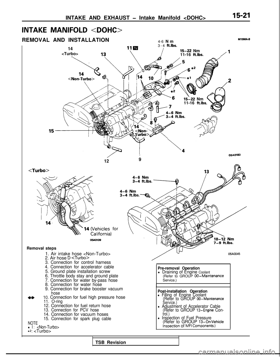
Removal steps 1. Air intake hose
2. Air hose
D 3. Connection for control harness
4. Connection for accelerator cable 5. Ground plate installation screw
6. Throttle body stay and ground plate
7. Connection for water by-pass hose
8. Connection for water hose
9. Connection for brake booster vacuum
hose10. Connection for fuel high pressure hose11. O-ring12. Connection for fuel return hose13. Connection for PCV hose14. Connection for vacuum hoses15. Connection for spark plug cableNOTEl l : +2:
05A0045
Pre-removal Operationl Draining of Engine Coolant(Refer to GROUP 00-MaintenanceService.)
Post-installation Operationl Filling of Engine Coolant (Refer to GROUP 00-Maintenance
Service.)
l Adjustment of Accelerator Cable (Refer to GROUP 13-Engine Con-trol.)l Inspection of Fuel Pressure(Refer to GROUP 13-On-Vehiclelnseection of MFI Comgonents.)
TSB Revision
Page 617 of 1273
INTAKE AND EXHAUST -Exhaust Manifold 15-31
EXHAUST MANIFOLD
REMOVAL AND INSTALLATION
12-15
Nm
Removal
12-15.Nm - g-11
ft.lbs.
steps
9-l 1 ftlbs.
lh ./-I
‘Uc Ml5NA.C
05AO192
Coolant
(Refer to GROUP
00-Maimtenance Service.)eDraining and Refilling Engine
1. Radiator (Referto GROUP 14-Radiator.)
2. Connection for air intake hose
3. Connection for vacuum hose
4. Connection for air hose A 5. Oxygen sensor connector
6. Air outlet fitting
7. Gasket
8. Heat protector A 9. Heat protector
B10. Self-locking nut
11. Engine hanger
12. Eye bolt
‘\!I 1
5
Ilation Operationl Draining and Refilling Engine
Oil
-
(Refer to GROUP 00-Main.tenance Service.)
13. Gasket14. Connection for water hose15. Connection for water pipe.B16. Self-locking nut17. Gasket18. Exhaust manifold
19. Exhaust manifold gasket
20. Ring
21. Gasket
TSB Revision1