1989 MITSUBISHI GALANT engine coolant
[x] Cancel search: engine coolantPage 198 of 1273
13-56 FUEL SYSTEM
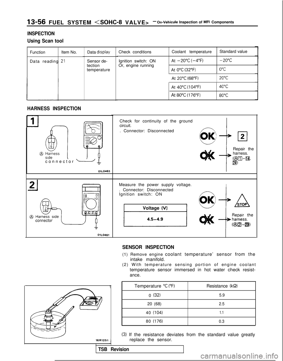
INSPECTION
Using Scan tool
FunctionItem No.
Data reading
-*LI
Data display
Sensor de-
tection
temperature
HARNESS INSPECTION
connector OlLO461Check conditions
Ignition switch: ON
Or, engine running Coolant temperature
Standard value
At
-20°C (-4°F)-20°C
At 0°C (32°F)0°C I
At
20°C (68°F)20°C
connector - Ic
OIL0463L
-16R1251
Temperature “C (“F)Resistance (kS2)
0 (32)5.9
20 (68)2.5
40 (104)1.1
80 (176) 0.3
(3) If the resistance deviates from the standard value greatly
replace the sensor.
J
TSB Revision
At 40°C (104°F)40°C
At 80°C (176°F)80°C
1
Check for continuity of the ground
circuit.
. Connector: Disconnected
Repair the
harness.
b&XII-@.
lm
Measure the power supply voltage.I. Connector: Disconnected
Ignition switch: ONVoltage
(VI
SENSOR INSPECTION
(1) Remove engine coolant temperature’ sensor from the
intake manifold.
(2) With temperature sensing portion of engine coolan
t
temperature sensor immersed in hot water check resist-
ance.
Page 199 of 1273
FUEL SYSTEM
INSTALLATION
(1) Apply sealant
3M
NUT locking No.41 71 or equivalent to
threaded portion.
(2) Install engine coolant temperature sensor and tighten it to specified torque.
Sensor tightening torque:
20-40 Nm (15-29 ft.lbs.1
(3) Fasten harness connectors securely
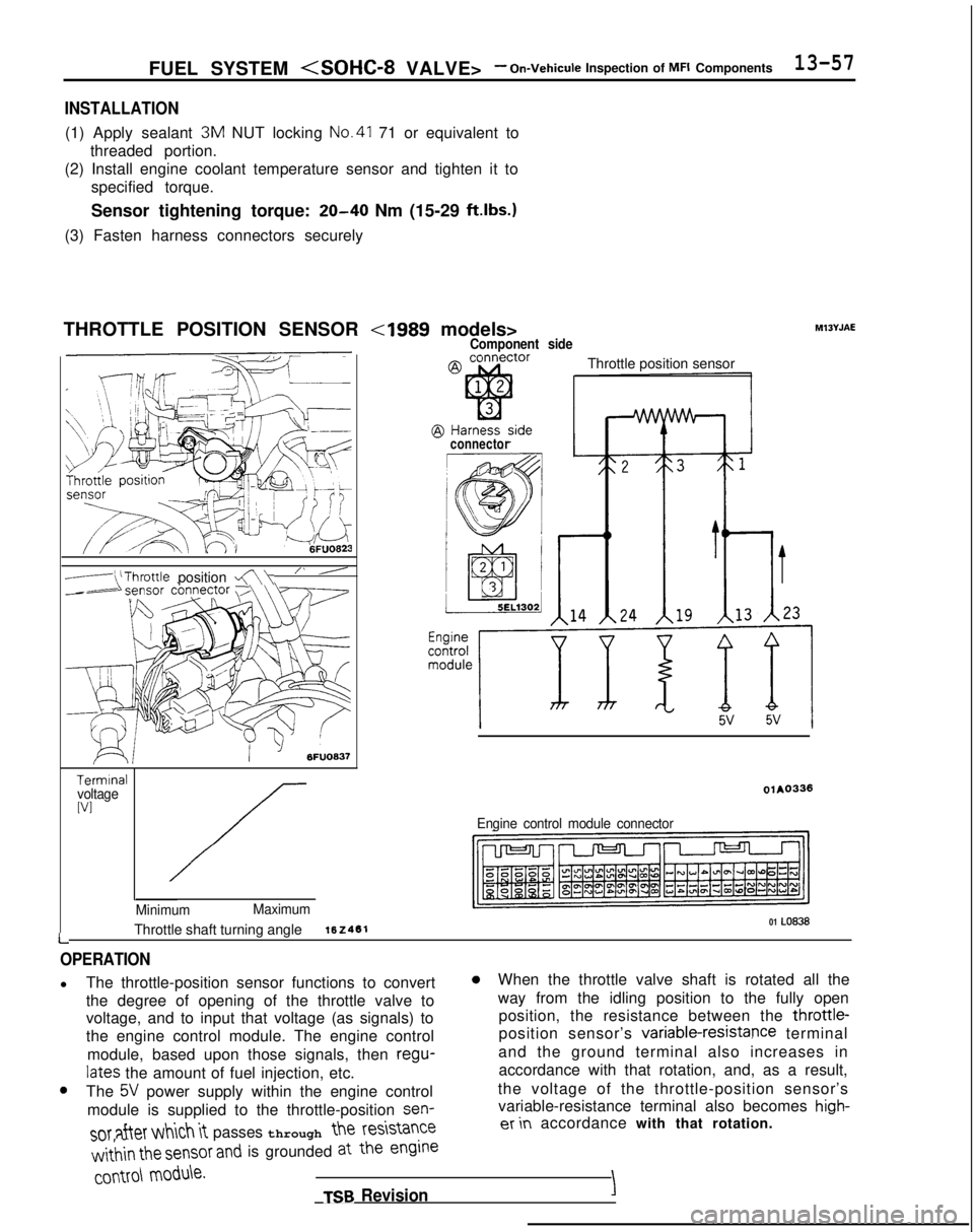
THROTTLE POSITION SENSOR
-(‘Throttle position a\“ ’
6FUO637
TerminalvoltageWI
L
Minimum Maximum01 LO838Throttle shaft turning angle162461
Component side
Throttle position sensor
connector
olAO336
Engine control module connector Ml3YJAE
OPERATION
l
The throttle-position sensor functions to convert0When the throttle valve shaft is rotated all the
the degree of opening of the throttle valve to way from the idling position to the fully open
voltage, and to input that voltage (as signals) to position, the resistance between the throttle-
the engine control module. The engine control position sensor’s variable-resistapce
terminal
module, based upon those signals, then regu-
and the ground terminal also increases in
lates the amount of fuel injection, etc. accordance with that rotation, and, as a result,0The 5V power supply within the engine control
the voltage of the throttle-position sensor’s
module is supplied to the throttle-position sen-
variable-resistance terminal also becomes high-
SOT after which it passes through the
resistanceer in
accordance with that rotation.
w&in the sensor and is grounded at the engine
COMO\
module.
TSB RevisionI
Page 207 of 1273
FUEL SYSTEM
(1) Improper adjustment of the basic idling speed.
(2) Deposits adhering to the ttirottle valve.
(3) Air being taken into the intake manifold due to a gasket leak, etc.
OPERATION
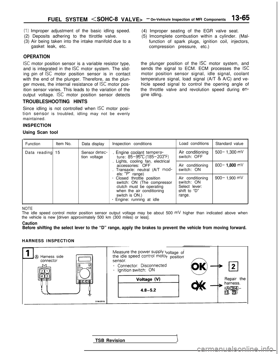
ISC motor position sensor is a variable resistor type,
and is integrated in the
ISC motor system. The slid-
ing pin of
ISC motor position sensor is in contact
with the end of the plunger. Therefore, as the plun- ger moves, the internal resistance of
ISC motor pos-
ition sensor varies. This leads to the variation of the (4) Improper seating of the EGR valve seat.
(5) lmcomplete combustion within a cylinder. (Mal-
function of spark plugs, ignition coil, injectors,
compression pressure, etc.)
the plunger position of the
ISC motor system, and
sends the signal to ECM. ECM processes the
ISC
motor position sensor signal, idle signal, coolant
temperature signal, load signal (A/T &
A/C) and ve-
hicle speed signal to control the opening angle of
the throttle valve and revolution speed during
en-
output voltage. ISC motor position sensor detects gine idling.
TROUBLESHOOTING HINTS
Since idling is not controlled when ISC motor posi-
tion sensor is troubled, idling may not be evenly
maintained.
INSPECTION
Using Scan tool
FunctionItem No. Data display Inspection conditions Load conditions
Standard value
Data reading 15 Sensor detec-
. Engine coolant tempera-
Air conditioning 500- 1,300 mV
tion voltage
ture: 85-95’C (185-203°F)
switch: OFF
. Lights, cooling fan, electrical accessories: OFF Air conditioning 800-
1,800 mV. Transaxle: neutral (A/T
mod-
switch: ON
els: “P”
range)
1 Closed throttle position Air conditioning900- 1,900 mVswitch: ON (The compressorswitch: ON
clutch must be operating Select lever:
when the air conditioning shift to “D”
switch is ON.)
range.* Engine: running at idle
NOTEThe idle speed control motor position sensor output voltage may be about\
500 mV higher than indicated above when
the vehicle is new [driven approximately 500 km (300 miles) or less].
CautionBefore shifting the select lever to the “D” range, apply the brake\
s to prevent the vehicle from moving forward.
HARNESS INSPECTION
Measure the power supply voltage of
the idle speed control motor position
ei;;;it;;sco$ected
__...._ -.-
TSB Revision
Page 216 of 1273
13-74 FUEL SYSTEM
Hint 4:
If idling is possible even though the crankshaft posi-
tion sensor indicated rpm is a deviation from the standard value, the cause is usually a malfunction of
something other than the crankshaft position sen-
sor.
Examples:
(1) Malfunction of the coolant-temperature sensor.
(2) Malfunction of the idling-speed control motor.
(3) Improper adjustment of the standard idling
speed.
INSPECTION
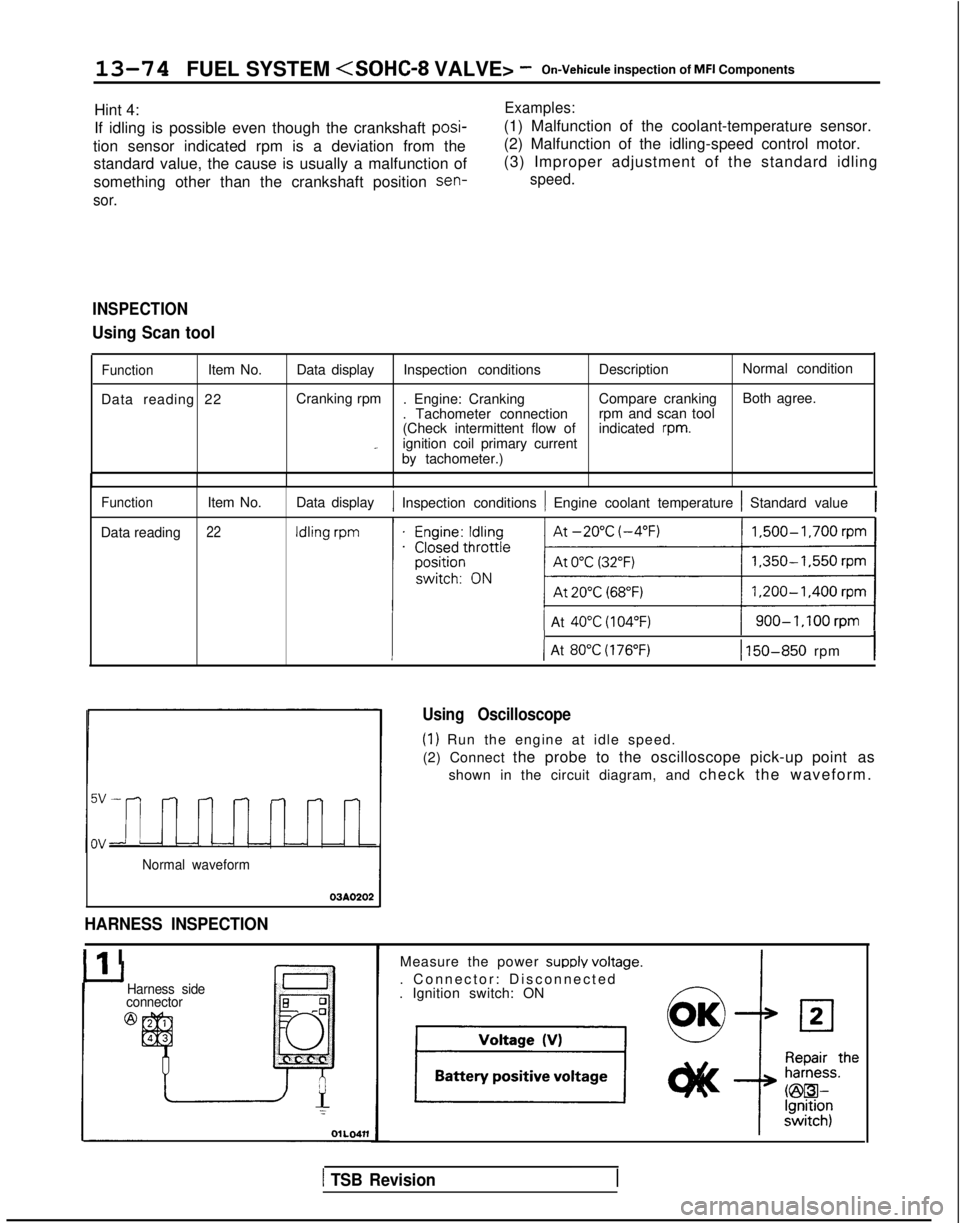
Using Scan tool
FunctionItem No.
Data reading 22 Data display
Inspection conditions DescriptionNormal condition
Cranking rpm . Engine: Cranking Compare crankingBoth agree.
. Tachometer connection rpm and scan tool
(Check intermittent flow of indicated
rpm._ignition coil primary current
by tachometer.)
Function
Data reading Item No.22
Data display1 Inspection conditions 1 Engine coolant temperature 1 Standard value1
1 At 40°C (104°F)1 900-1,100rpm 1
III-I( At 80°C (176°F)1 150-850 rpm
Normal waveform
03AO202
HARNESS INSPECTION
Ilr I
Using Oscilloscope
(1) Run the engine at idle speed.
(2) Connect the probe to the oscilloscope pick-up point as
shown in the circuit diagram, and check the waveform.
Harness side
connector
@
Measure the power SUPPIY voltaoe.
. Connector: Disconnected
-. Ignition switch: ON
1 TSB Revision
Page 230 of 1273
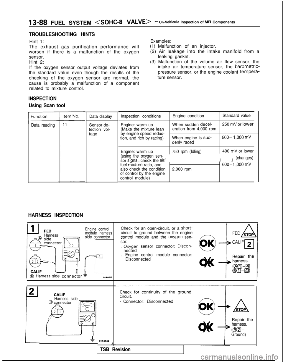
13-88 FUEL SYSTEM
TROUBLESHOOTING HINTS
Hint I’
The exhaust gas purification performance will
Examples:
(1) Malfunction of an injector.
worsen if there is a malfunction of the oxygen sensor. Hint 2:
If the oxygen sensor output voltage deviates from
the standard value even though the results of the
checking of the oxygen sensor are normal, the
cause is probably a malfunction of a component related to mixture control. (2) Air leakage into the intake manifold from a
leaking gasket.
(3) Malfunction of the volume air flow sensor, the intake air temperature sensor, the barometric-
pressure sensor, or the engine coolant tempera-
ture sensor.
Data reading
INSPECTION
Using Scan tool
HARNESS INSPECTION
Data display
Sensor de-
tection vol-
tage Inspection conditions
Engine conditionStandard value
Engine: warm up When sudden decel-
250
mV or lower
(Make the mixture lean eration from 4,000 rpm
by engine speed reduc-
tion, and rich by racing) When engine is sud-
500- 1,000 mV
denly raced
Engine: warm up750 rpm (Idling)
(using the oxygen sen-
sor sianal.
check the air/
400
mV or lower
I I
(changes)
fuel mixture ratio, and600-l ,000 mValso check the condition 2,000 rpm
of control by the engine
control module)
I CALIF@I Hal
FEDHarness
ness
side
connector
Engine control
module harness
side connector
Check for an open-circuit, or a short-circuit to ground between the engine
control module and the oxwen sen-f7 _-
~~SOT.‘-. r$;rdn sensor connector: Drscon-
. Engine control module connector:Disconnected CALIF
Harness side
Check for continuity of the ground
.“‘..“...;;”
Repair theharness.
KEEI-Ground)
1
TSB Revision
Page 231 of 1273
FUEL SYSTEM
:Federab
:California>
Ea
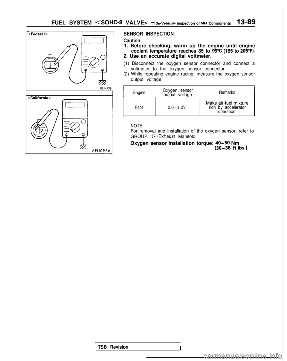
SENSOR INSPECTION
Caution
1. Before checking, warm up the engine until engine
coolant temperature reaches 85 to 95°C (185 to 205°F).
2. Use an accurate digital voltmeter.
(1) Disconnect the oxygen sensor connector and connect a voltmeter to the oxygen sensor connector.
(2) While repeating engine racing, measure the oxygen sensor
output voltage.
,
IEngineOxygen sensoroutput voltageRemarks
Race0.6-l .OVMake air-fuel mixturerich by acceleratoroperation
NOTE
For removal and installation of the oxygen sensor, refer to
GROUP
15-Exhaust Manifold.
Oxygen sensor installation torque:
40-50 Nm
(30-36 ft.lbs.1
TSB Revision I
Page 233 of 1273
FUEL SYSTEM
Inspection of MFI Components13-91
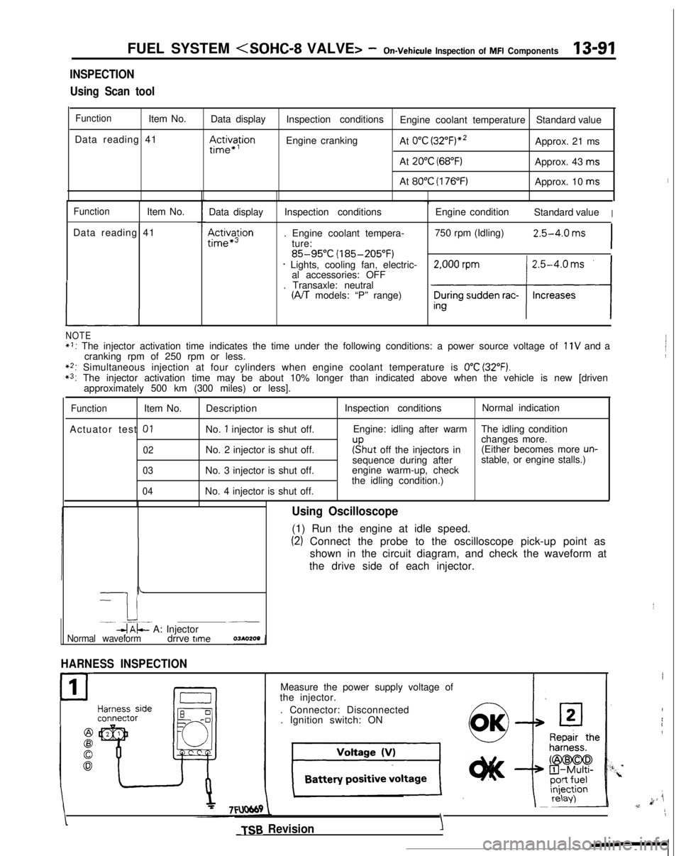
INSPECTION
Using Scan tool
FunctionItem No. Data display
Data reading 41
III~~~ion
Inspection conditions Engine coolant temperature Standard value
Engine cranking At
0°C (3~2°F)“~Approx. 21 ms
At
20°C (68°F)Approx. 43 ms
At
80°C (176°F)Approx. 10 ms
FunctionItem No.
Data reading 41
L
Data display
Ac&a$ion
Inspection conditions
. Engine coolant tempera- ture:
85-95°C (185-205°F)* Lights, cooling fan, electric-al accessories: OFF
. Transaxle: neutral
(A/T models: “P” range) Engine condition
Standard value
I
750 rpm (Idling)2.5-4.0 ms
I
NOTE*I: The injector activation time indicates the time under the following con\
ditions: a power source voltage of 11V and a
cranking rpm of 250 rpm or less.
**: Simultaneous injection at four cylinders when engine coolant temperatur\
e is 0°C (32°F).*3: The injector activation time may be about 10% longer than indicated abo\
ve when the vehicle is new [driven approximately 500 km (300 miles) or less].
FunctionItem No.
Actuator test
01
02
03
04
Description
No.
1 injector is shut off.
No. 2 injector is shut off.
No. 3 injector is shut off.
No. 4 injector is shut off. Inspection conditions
Normal indication
Engine: idling after warm The idling condition
changes more.
r”sput off the injectors in(Either becomes more un-sequence during after stable, or engine stalls.)
engine warm-up, check
the idling condition.)
-
I i-. --.-~-db$- A: Injector~__
Normal waveformdrrve time
HARNESS INSPECTION
1
P
Using Oscilloscope
(1) Run the engine at idle speed.
(2) Connect the probe to the oscilloscope pick-up point as
shown in the circuit diagram, and check the waveform at
the drive side of each injector.
Measure the power supply voltage of
the injector.
. Connector: Disconnected. Ignition switch: ON
TSB Revision
I
I
4
i1
k ji,v,11
\
YIY’.
Page 248 of 1273
13-106
FUEL SYSTEM
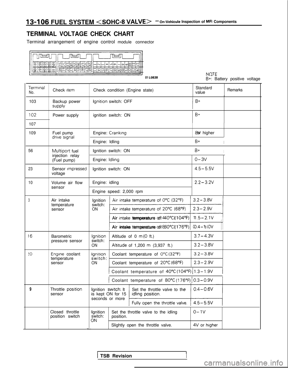
TERMINAL VOLTAGE CHECK CHART
Terminal arrangement of engine control module connector NflTF
01 LO838
. .- -B+: Battery positive voltage
Terminal
No.Check condition (Engine state)StandardvalueRemarksCheck item
103
Backup power supply lgnitron
switch: OFF
102Power supply ignition switch: ONB+
107
109
Fuel pump dnve signal
Engine: Cranking 8V or higher
Engine: Idling
B+I
Ignition switch: ON
Engine:
ldlrng
Ignition switch: ON
Engine: idling
Engine speed: 2,000 rpm
B+I
o-3v
4.5- 5.5v
2.2- 3.2V
56
23
10
Multiport fuel
injection relay
(Fuel pump)
Sensor
rmpressecvoltage
Volume air flow
sensor
Air intake
temperature sensor Ignition
Air intake temperature of
0°C (32°F)switch:ONAir Intake temperature of 20°C (68°F); ji/
Air Intake temperature of 40°C (104°F)1.5-2.1V
Air intake temperature of 80°C (176’F)0.4- 1 .OV
Barometric
pressure sensor
Ignition
Altitude of 0 m (0 ft.)3.7-4.3vswitch:ON Altitude
of 1,200 m (3,937 ft.)3.2-3.av
Engrne coolant lgnitron
Coolant temperature of 0°C (32°F)3.2-3.Wtemperature switch: -sensorONCoolant temperature of 20°C (68°F)2.3-2.9v
1 Coolant temperature of 40°C
(104°F) 1 1.3- 1.9V(
) Coolant temperature of 80°C
(176’F)
1 0.3-0.9V
Throttle posrtionsensor Ignition swatch: It
Set the throttle valve to the
is kept ON for 15
seconds or more
Closed throttle position switchII
I
I
-
Ignition Set the throttle valve to the idlingo-1vswitch:position.3NSlightly open the throttle valve. 4V
or higher
3
16
!O
9
1 TSB Revision1