1989 MITSUBISHI GALANT engine coolant
[x] Cancel search: engine coolantPage 78 of 1273
II-28ENGINE
MD998051-01OPTIONAL\
Front of engine +Intake side
km>
Exhaust side
OlR0391
OlRD417
Identification
mark I
6EN025
OlRO416
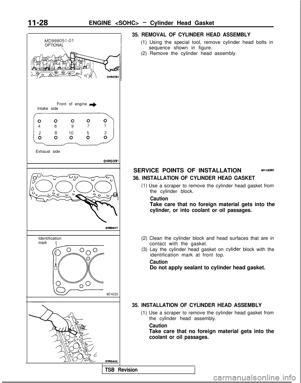
35. REMOVAL OF CYLINDER HEAD ASSEMBLY
(1) Using the special tool, remove cylinder head bolts insequence shown in figure.
(2) Remove the cylinder head assembly.
SERVICE POINTS OF INSTALLATION
MllJDBC
36. INSTALLATION OF CYLINDER HEAD GASKET
(1) Use a scraper to remove the cylinder head gasket from the cylinder block.
Caution
Take care that no foreign material gets into the
cylinder, or into coolant or oil passages.
(2) Clean the cylinder block and head surfaces that are in contact with the gasket.
(3) Lay the cylinder head gasket on cylider
block with the
identification mark at front top.
Caution
Do not apply sealant to cylinder head gasket.
35. INSTALLATION OF CYLINDER HEAD ASSEMBLY
(1) Use a scraper to remove the cylinder head gasket from
the cylinder head assembly.
Caution
Take care that no foreign material gets into the
coolant or oil passages.
TSB Revision
Page 80 of 1273
II-30ENGINE
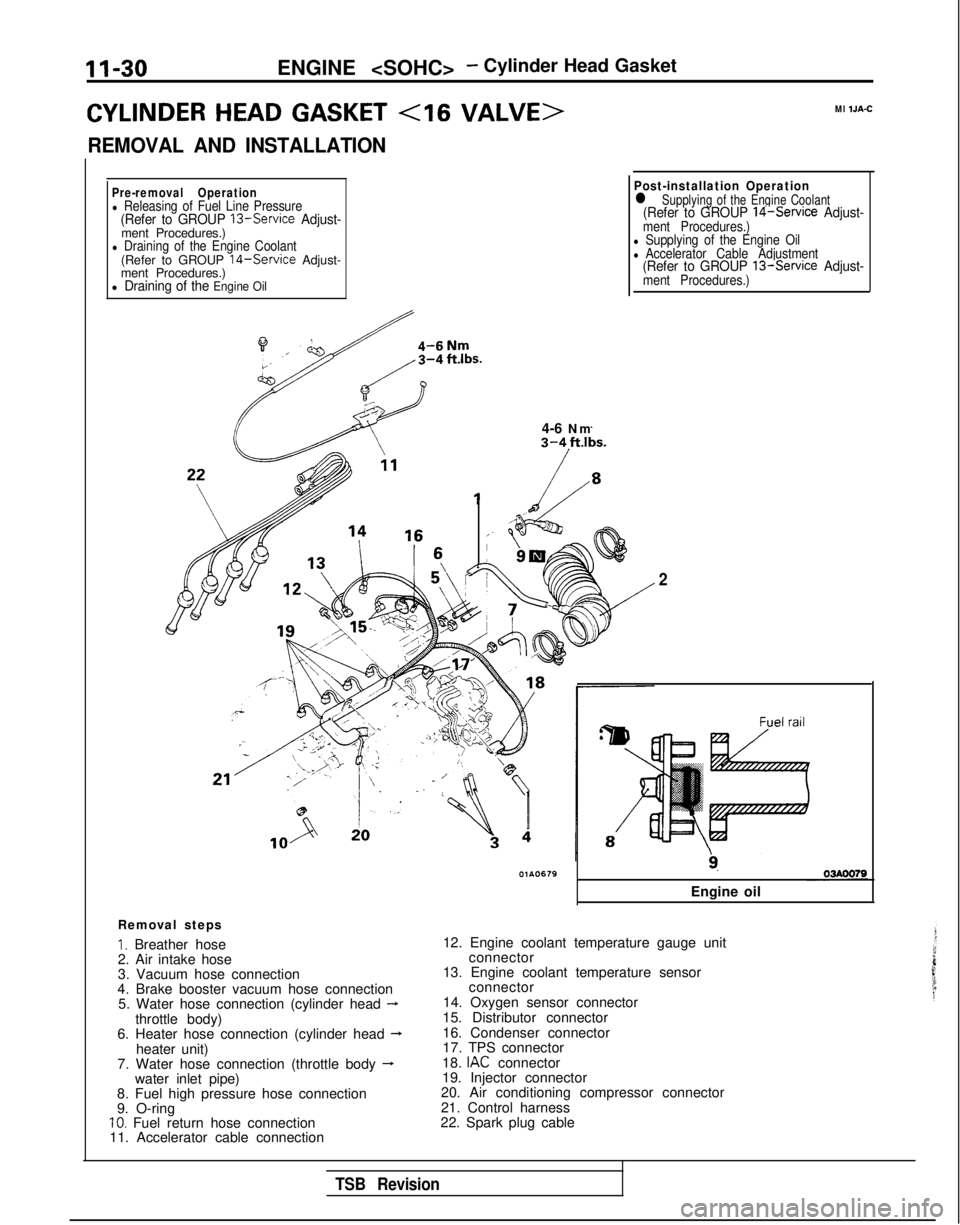
CYLINDER HEAD GASKET
REMOVAL AND INSTALLATION
Ml IJA-C
Pre-removal Operationl Releasing of Fuel Line Pressure(Refer to GROUP 13-Service Adjust-ment Procedures.)l Draining of the Engine Coolant(Refer to GROUP 14-Service Adjust-
ment Procedures.)
l Draining of the Engine Oil
il4-6 Nm
Post-installation Operationl Supplying of the Engine Coolant(Refer to GROUP 14-Service Adjust-ment Procedures.)l Supplying of the Engine Oill Accelerator Cable Adjustment(Refer to GROUP 13-Service Adjust-ment Procedures.)
Removal steps
I. Breather hose
2. Air intake hose
3. Vacuum hose connection
4. Brake booster vacuum hose connection 5. Water hose connection (cylinder head
-throttle body)
6. Heater hose connection (cylinder head --Lheater unit)
7. Water hose connection (throttle body -water inlet pipe)
8. Fuel high pressure hose connection
9. O-ring
10. Fuel return hose connection
11. Accelerator cable connection
2
9.
Engine oil
12. Engine coolant temperature gauge unit connector
13. Engine coolant temperature sensor connector
14. Oxygen sensor connector
15. Distributor connector
16. Condenser connector
17. TPS connector
18.
IAC connector
19. Injector connector
20. Air conditioning compressor connector
21. Control harness
22. Spark plug cable
TSB Revision
Page 82 of 1273
11-32ENGINE
- Winder Head Gasket
sprocket
’lG90001
Intake side Front of engine e
I
Exhaust side\olCOll!iLoosening order
SERVICE POINTS OF REMOVALMllJEAZ
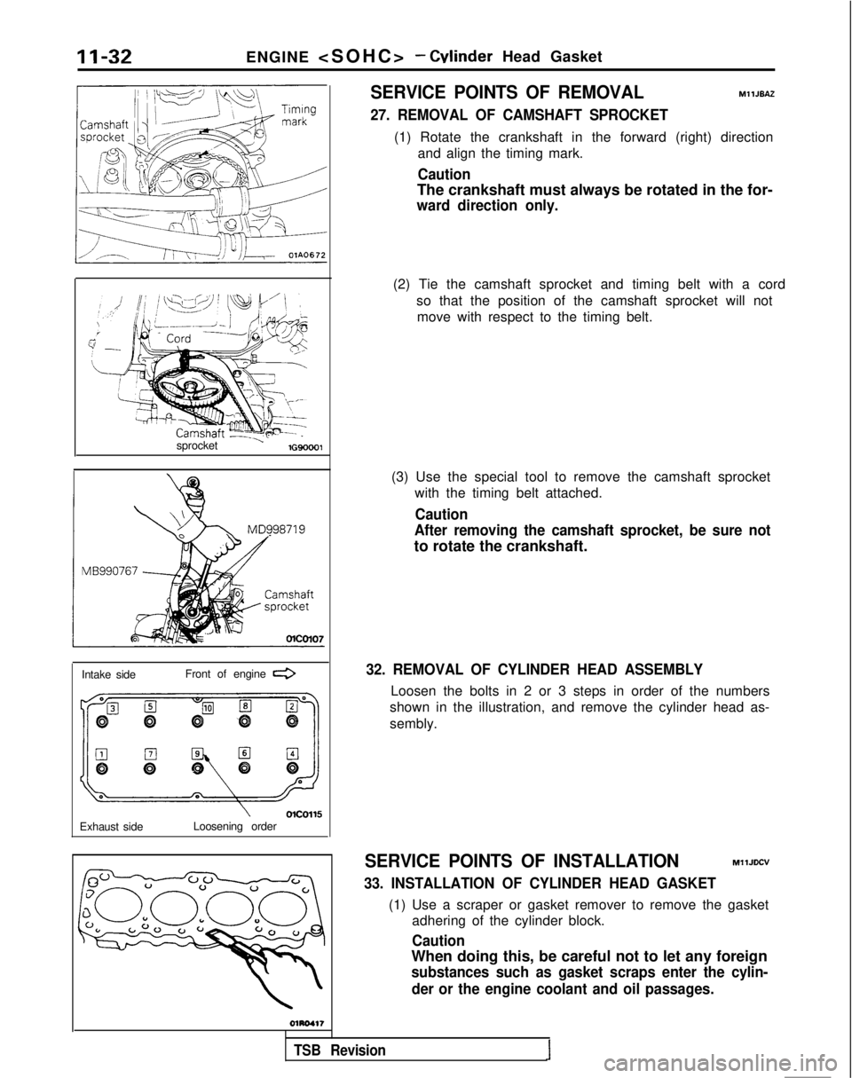
27. REMOVAL OF CAMSHAFT SPROCKET
(1) Rotate the crankshaft in the forward (right) direction
and align the timing mark.
Caution
The crankshaft must always be rotated in the for-
ward direction only.
(3) Use the special tool to remove the camshaft sprocketwith the timing belt attached.
Caution
After removing the camshaft sprocket, be sure not
to rotate the crankshaft.
32. REMOVAL OF CYLINDER HEAD ASSEMBLY
Loosen the bolts in 2 or 3 steps in order of the numbers
shown in the illustration, and remove the cylinder head as-
sembly.
SERVICE POINTS OF INSTALLATIONMllJDCV
33. INSTALLATION OF CYLINDER HEAD GASKET
(1) Use a scraper or gasket remover to remove the gasket adhering of the cylinder block.
Caution
When doing this, be careful not to let any foreign
substances such as gasket scraps enter the cylin-
der or the engine coolant and oil passages.
(2) Tie the camshaft sprocket and timing belt with a cord
so that the position of the camshaft sprocket will notmove with respect to the timing belt.
TSB Revision1
Page 83 of 1273
ENGINE
Identification markr3
Intake
side “4G63K”
Front of
Exhaust side
OlA0669
Front of engine
I)Intake side
Exhaust side
OlR0391
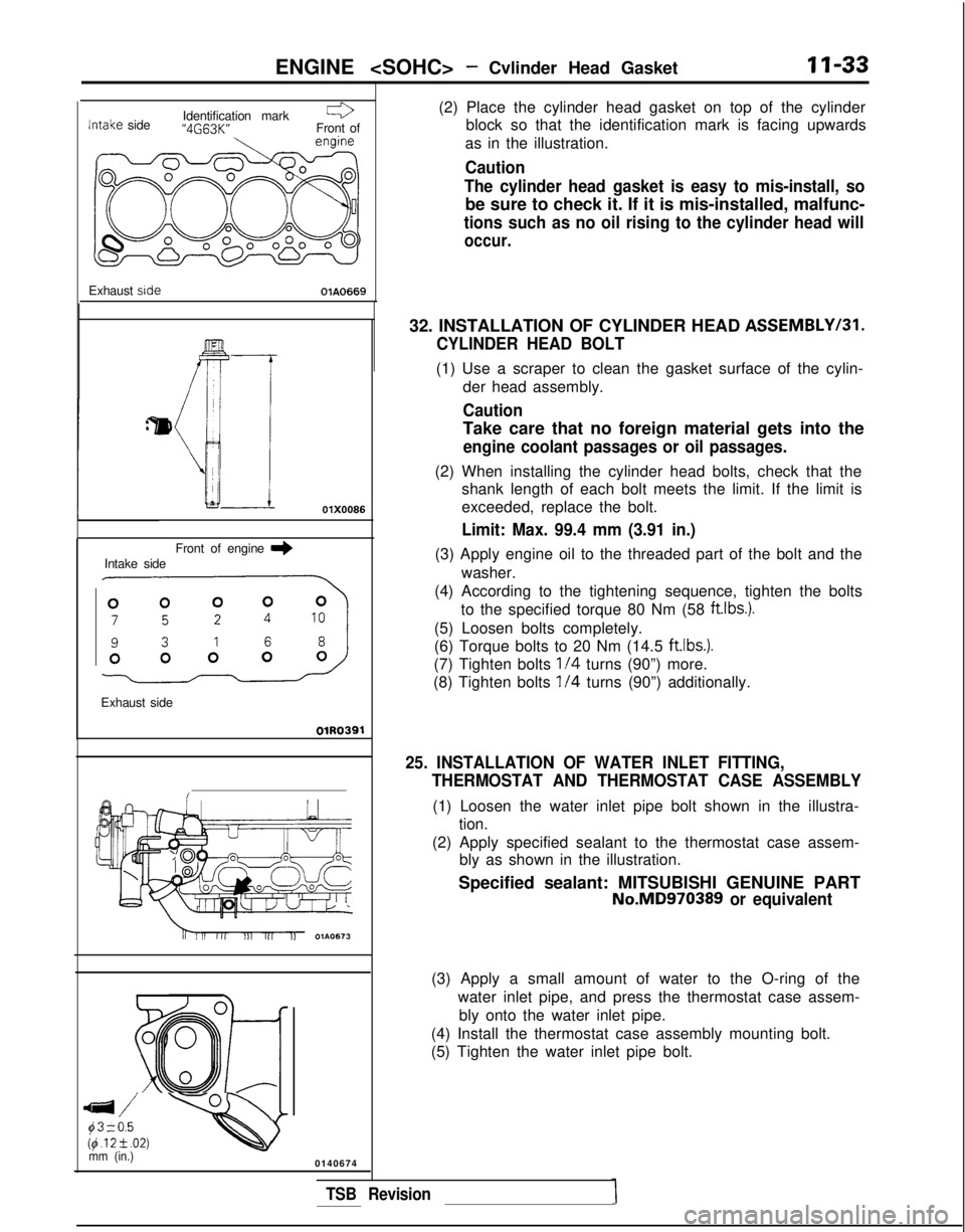
Ei;. -Qmm (in.)0140674 (2) Place the cylinder head gasket on top of the cylinder
block so that the identification mark is facing upwards
as in the illustration.
Caution
The cylinder head gasket is easy to mis-install, so
be sure to check it. If it is mis-installed, malfunc-
tions such as no oil rising to the cylinder head will
occur.
32. INSTALLATION OF CYLINDER HEAD ASSEMBLYI31.
CYLINDER HEAD BOLT
(1) Use a scraper to clean the gasket surface of the cylin-
der head assembly.
Caution
Take care that no foreign material gets into the
engine coolant passages or oil passages.
(2) When installing the cylinder head bolts, check that theshank length of each bolt meets the limit. If the limit is
exceeded, replace the bolt.
Limit: Max. 99.4 mm (3.91 in.)
(3) Apply engine oil to the threaded part of the bolt and the
washer.
(4) According to the tightening sequence, tighten the bolts to the specified torque 80 Nm (58 ftlbs.).
(5) Loosen bolts completely.
(6) Torque bolts to 20 Nm (14.5
ft.lbs.).
(7) Tighten bolts l/4 turns (90”) more.
(8) Tighten bolts
l/4 turns (90”) additionally.
25. INSTALLATION OF WATER INLET FITTING, THERMOSTAT AND THERMOSTAT CASE ASSEMBLY
(1) Loosen the water inlet pipe bolt shown in the illustra-tion.
(2) Apply specified sealant to the thermostat case assem- bly as shown in the illustration.
Specified sealant: MITSUBISHI GENUINE PART
No.MD970389 or equivalent
(3) Apply a small amount of water to the O-ring of the
water inlet pipe, and press the thermostat case assem-bly onto the water inlet pipe.
(4) Install the thermostat case assembly mounting bolt.
(5) Tighten the water inlet pipe bolt.
TSB Revision
Page 107 of 1273
ENGINE
OlR0340
7EN0393
1SERVICE ADJUSTMENT PROCEDUBFzo
ENGINE OIL CHECK
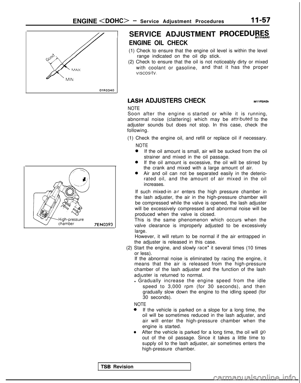
(1) Check to ensure that the engine oil level is within the level
range indicated on the oil dip stick.
(2) Check to ensure that the oil is not noticeably dirty or mixed
with coolant or gasoline, and that it has the proper
vtscosity. IASH
ADJUSTERS CHECK
NOTE MllFEAGb
Soon after the engine IS started or while it is running,
abnormal noise (clattering) which may be attributed
to the
adjuster sounds but does not stop. In this case, check the
following.
(1) Check the engine oil, and refill or replace oil if necessary.
NOTE 0
If the oil amount is small, air will be sucked from the oil
strainer and mixed in the oil passage. 0
If the oil amount is excessive, the oil will be stirred by
the crank and mixed with a large amount of air. 0
Air and oil can not be separated easily in the deterio-
rated oil, and the amount of air mixed in the oil
increases.
If such mixed-in air enters the high pressure chamber in
the lash adjuster, the air in the high-pressure chamber will
be compressed while the valve is opened, the lash adjuster
will be excessively compressed and abnormal noise will be produced when the valve is closed.
This is the same phenomenon which occurs when the
valve clearance is improperly adjusted to be excessively
large.
However, it will return to be normal if the air entrapped in
the adjuster is released in this case.
(2) Start the engine, and slowly
race* it several times (10 times
or less). If the abnormal noise is eliminated by racing the engine, it
means that the air is released from the high-pressure
chamber of the lash adjuster and the function of the lash adluster
is returned to normal.
l Gradually increase the engine speed from the idle
speed to 3,000 rpm (for 30 seconds), and then
gradually slow down the engine to the idling speed (for
30 seconds).
NOTE 0
If the vehicle is parked on a slope for a long time, the
oil will be sometimes reduced in the lash adjuster, and
air will enter the high-pressure chamber when the
engine is started.
lAfter the vehicle is parked for a long time, the oil will go
out of the oil passage. Since it takes a little time to
supply oil to the lash adjuster, air sometimes enters the
high-pressure chamber.
TSR Revision
Page 108 of 1273
11-58ENGINE
4 Timing belt sideI
6EN0515
(3) lf
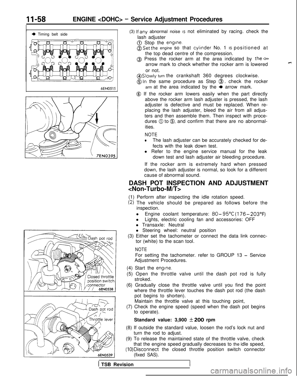
any abnormal noise IS not eliminated by racing. check the
lash adjuster
@ Stop the engine.
@ Set the engine so that cylinder
No. 1 IS positioned at
the top dead centre of the compression.
@ Press the rocker arm at the area indicated by the+
arrow mark to check whether the rocker arm is lowered
or not.
@ Slowly turn the crankshaft 360 degrees clockwise.
@ ln the same procedure as Step 0, check the rocker
arm at the area indicated by the
4 arrow mark.
@ If the rocker arm lowers easily when the part directly above the rocker arm lash adjuster is pressed, the lash
adjuster is defective and must be replaced. When re- placing the lash adjuster, bleed the air from all adjus-
ters and then assemble them. Then inspect with proce- dures
@I to 0, and confirm that there are no abnormal-
ities.
NOTE
lThe lash adjuster can be accurately checked for de-
fects with the leak down test.
l Refer to the engine service manual for the leak
down test and lash adjuster air bleeding procedure.
If the rocker arm is extremely hard when pressed
down, the lash adjuster is normal, so look for a different
cause of abnormal sound.
DASH POT INSPECTION AND ADJUSTMENT
(1) Perform after inspecting the idle rotation speed.
(2) The vehicle should be prepared as follows before the inspection.
l Engine coolant temperature:
80- 95°C
(176- 203°F)
lLights, electric cooling fan and accessories: OFF
l Transaxle: Neutral
l Steering wheel: neutral position
(3) Either set the tachometer or connect the data link connec- tor (white) to the scan tool.
NOTE
For setting the tachometer. refer to GROUP 13 - Service
Adjustment Procedures.
(4) Start the
engine.
(5) Open the throttle valve until the dash pot rod is fully
stroked.
(6) Gradually close the throttle valve until you find the point where the throttle lever touches the dash pot rod (the dashpot begins to shorten).
Maintain the throttle valve at this touching point,
(7) Check the engine speed (speed when the dash pot begins to operate).
Standard value: 3,900
f 200 rpm
(8) If outside the standard value, loosen the rod’s lock nut and turn the rod to adjust.
(9) To release the maintained state of the throttle valve, check that the engine speed gradually decreases to the idle speed, (10)Disconnect
the closed throttle position switch connector
(fixed SAS).
1 TSB Revision
Page 109 of 1273
ENGINE
7 Go;;ikv position
switch
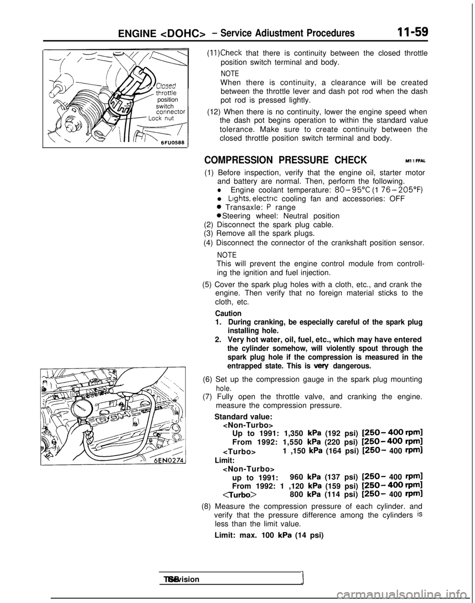
(11)Check that there is continuity between the closed throttle
position switch terminal and body.
NOTE
When there is continuity, a clearance will be created between the throttle lever and dash pot rod when the dash
pot rod is pressed lightly.
(12) When there is no continuity, lower the engine speed when the dash pot begins operation to within the standard value
tolerance. Make sure to create continuity between the
closed throttle position switch terminal and body.
COMPRESSION PRESSURE CHECK Ml 1 FFAL
(1) Before inspection, verify that the engine oil, starter motor
and battery are normal. Then, perform the following.
lEngine coolant temperature: 80- 95°C
(1 76- 205’F)
l Lights, electnc
cooling fan and accessories: OFF
0 Transaxle: P range 0 Steering wheel: Neutral position
(2) Disconnect the spark plug cable.
(3) Remove all the spark plugs.
(4) Disconnect the connector of the crankshaft position sensor.
NOTE
This will prevent the engine control module from controll- ing the ignition and fuel injection.
(5) Cover the spark plug holes with a cloth, etc., and crank the engine. Then verify that no foreign material sticks to the
cloth, etc.
Caution
1.During cranking, be especially careful of the spark plug
installing hole.
2. Very hot water, oil, fuel, etc., which may have entered
the cylinder somehow, will violently spout through the
spark plug hole if the compression is measured in the
entrapped state. This is
vex/ dangerous.
(6) Set up the compression gauge in the spark plug mounting
hole.
(7) Fully open the throttle valve, and cranking the engine.
measure the compression pressure.
Standard value:
kPa (192 psi) [250- 400 rpml
From 1992: 1,550
kPa (220 psi) [250-400 rpm]
Limit:
up to 1991: 960
kPa (137 psi) [250- 400 rpml
From 1992: 1 ,120 kPa (159 psi) [250- 400 rpml
CTurbo>
800
kPa (114 psi) [250- 400 rpml
(8) Measure the compression pressure of each cylinder. and verify that the pressure difference among the cylinders
is
less than the limit value.
Limit: max. 100
kPa (14 psi) TSB Revision
I
Page 110 of 1273
II-60ENGINE
(9) If a cylinder’s compression pressure or pressure differenceis outside the limit, fill a small amount of engine oil through
the spark plug hole and repeat Items (7) and (8) above.
@ If the compression is increased when the oil is filled, the piston
and/or cylinder wall may be worn or
damaged.
@ If the compression is not Increased even though the oil is filled, the valve may be thermally seized, the valve
contact may be improper or pressure may leak at the
gasket. (10)Connect the connector of the crankshaft position sensor.
(1l)lnstall
the spark plug and spark plug cable.
(12)Erase the diagnostic trouble code with the scan tool or re-
connect the battery (-)
cable 10 seconds or more after it
was disconnected.
NOTE
This will erase the memory of the diagnostic trouble code which resulted from disconnection of the crankshaft posi-
tion sensor connector.
MANIFOLD VACUUM INSPECTION MllFNAD
(1) Before inspection and adjustment, put the vehicle into the following state.
l Engine coolant temperature:
85-95°C (185-205°F)
l Lights, motor cooling fan, and accessories: OFF
l Transaxle:
N (Neutral)
l Steering wheel: Neutral
(2) Check that the idling revolution speed is normal.
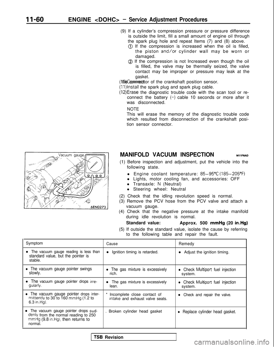
(3) Remove the PCV hose from the PCV valve and attach a
vacuum gauge.
(4) Check that the negative pressure at the intake manifold
during idle revolution is normal.
Standard value: Approx. 500 mmHg
(20 in.Hg)
(5) If outside the standard value, isolate the cause by referring to the following table and repair the fault.
Symptom
CauseRemedy
l The vacuum gauge reading is less thanstandard value, but the pointer isl Ignition timing is retarded. l Adjust the ignition timing.
stable.
l The vacuum gauge pointer swings
slowly.l The gas mixture is excessivelyrich.l Check Multiport fuel injectionsystem.
l The vacuum gauge pointer drops irre- gularly.
l The gas mixture is excessively
lean.l Check Multiport
fuel injectionsystem.
l The vacuum gauge pointer drops inter-mittently to 30 to 160 mmHg
(1.2 to * Incomplete close contact of Intake
and exhaust valve seats.l Check and repair the valve.
6.3 in.Hg).
l The vacuum gauge pointer drops sud- denly
from the normal reading to 250 . Broken cylinder head gasketl Replace cylinder head gasket.
mmHg (9.8 in.Hg), then returns tonormal.
TSB Revision