1989 MITSUBISHI GALANT engine coolant
[x] Cancel search: engine coolantPage 57 of 1273
ENGINE
OlR0340
1
SERVICE ADJUSTMENT PROCEDU$$o
ENGINE OIL CHECK
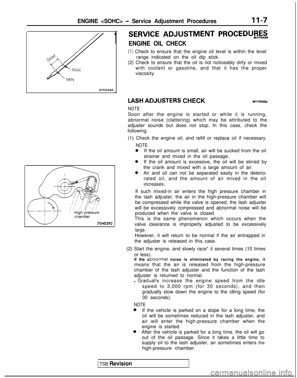
(1) Check to ensure that the engine oil level is within the level
range indicated on the oil dip stick.
(2) Check to ensure that the oil is not noticeably dirty or mixed
with coolant or gasoline, and that it has the proper
viscosity. IASH
ACIJUSTERS CHECKMllFEAGa
NOTE
Soon after the engine is started or while it is running,
abnormal noise (clattering) which may be attributed to the
adjuster sounds but does not stop. In this case, check the
following.
(1) Check the engine oil, and refill or replace oil if necessary.
NOTE
0If the oil amount is small, air will be sucked from the oil
strainer and mixed in the oil passage.
0If the oil amount is excessive, the oil will be stirred by
the crank and mixed with a large amount of air.
0Air and oil can not be separated easily in the deterio- rated oil, and the amount of air mixed in the oil
increases.
If such mixed-in air enters the high pressure chamber in
the lash adjuster, the air in the high-pressure chamber will be compressed while the valve is opened, the lash adjuster
will be excessively compressed and abnormal noise will be produced when the valve is closed.
This is the same phenomenon which occurs when the
valve clearance is improperly adjusted to be excessively
large.
However, it will return to be normal if the air entrapped in
the adjuster is released in this case.
(2) Start the engine, and slowly race* it several times (10 times or less).
If the
ablnormal noise is eliminated by racing the engine, it
means that the air is released from the high-pressure
chamber of the lash adjuster and the function of the lash
adjuster is returned to normal.
l
Graclually increase the engine speed from the idle
speed to 3,000 rpm (for 30 seconds), and then
gradually slow down the engine to the idling speed (for
30 seconds).
NOTE 0
If the vehicle is parked on a slope for a long time, the
oil will be sometimes reduced in the lash adjuster, and
air will enter the high-pressure chamber when the
engine is started. 0
After the vehicle is parked for a long time, the oil will go
out of the oil passage. Since it takes a little time to
supply oil to the lash adjuster, air sometimes enters the
high-pressure chamber.
1 TSB Revision
Page 58 of 1273
II-8ENGINE
8 VALVE
W Tlmlng belt side
il6
16
727
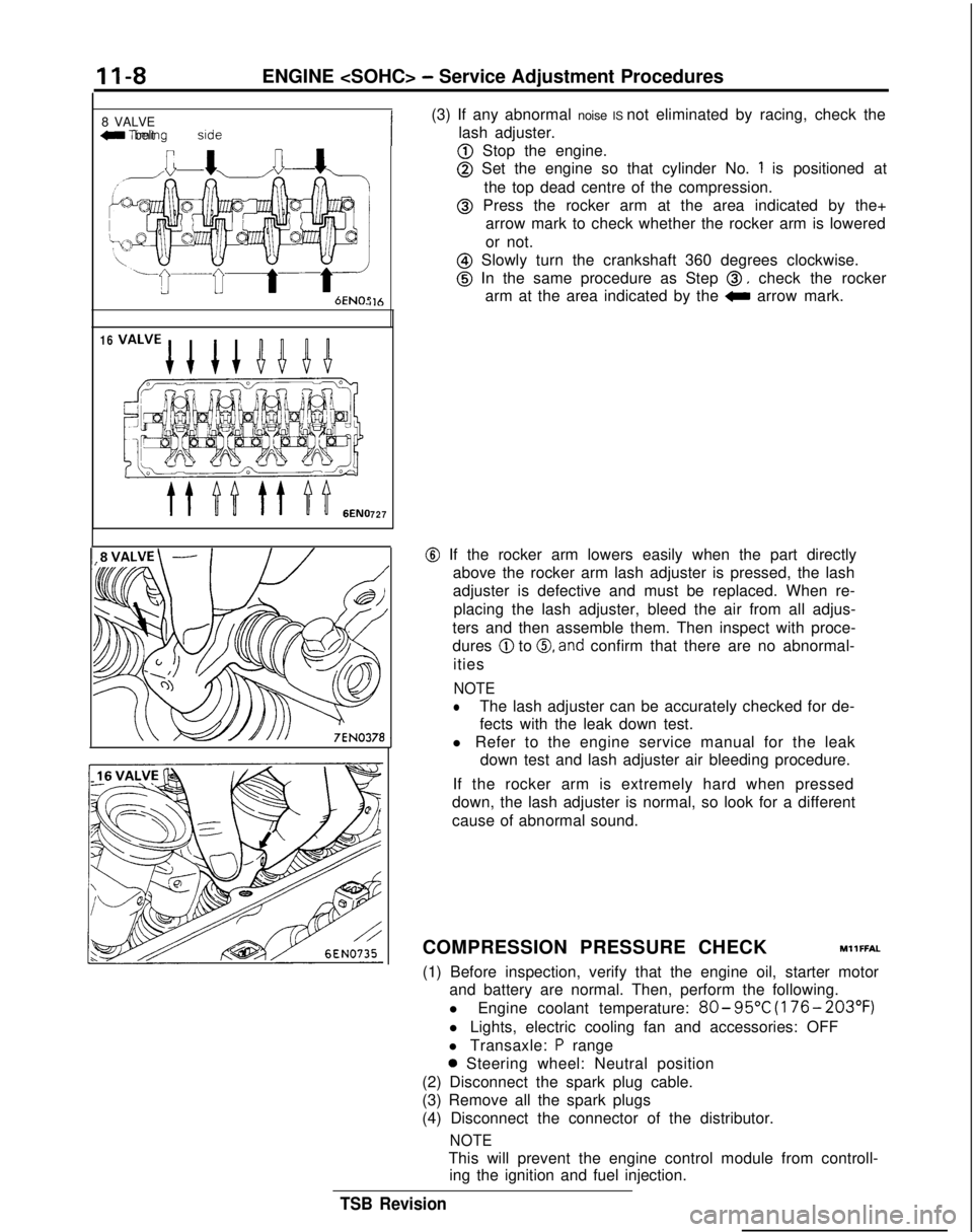
(3) If any abnormal noise IS not eliminated by racing, check the
lash adjuster.
@ Stop the engine.
@ Set the engine so that cylinder No. 1 is positioned at
the top dead centre of the compression.
@ Press the rocker arm at the area indicated by the+ arrow mark to check whether the rocker arm is lowered
or not.
@ Slowly turn the crankshaft 360 degrees clockwise.
@ In the same procedure as Step 0, check the rocker
arm at the area indicated by the
0 arrow mark.
@ If the rocker arm lowers easily when the part directly
above the rocker arm lash adjuster is pressed, the lash
adjuster is defective and must be replaced. When re-
placing the lash adjuster, bleed the air from all adjus-
ters and then assemble them. Then inspect with proce-
dures
@ to 0, and confirm that there are no abnormal-
ities
NOTE
lThe lash adjuster can be accurately checked for de-
fects with the leak down test.
l Refer to the engine service manual for the leak down test and lash adjuster air bleeding procedure.
If the rocker arm is extremely hard when pressed
down, the lash adjuster is normal, so look for a different
cause of abnormal sound.
COMPRESSION PRESSURE CHECK
MllFFAL
(1) Before inspection, verify that the engine oil, starter motor and battery are normal. Then, perform the following.
l Engine coolant temperature:
80- 95°C
(176- 203°F)
l Lights, electric cooling fan and accessories: OFF
l Transaxle:
P range
0 Steering wheel: Neutral position
(2) Disconnect the spark plug cable.
(3) Remove all the spark plugs
(4) Disconnect the connector of the distributor.
NOTE
This will prevent the engine control module from controll- ing the ignition and fuel injection.
TSB Revision
Page 59 of 1273

ENGINE
(5) Cover the spark plug holes with a cloth, etc., and crank the engine. Then verify that no foreign material sticks to the
cloth, etc.
Caution
1. During cranking, be especially careful of the spark plug
installing hole.
2.Very hot water, oil, fuel, etc., which may have entered
the cylinder somehow, will violently spout through the spark plug hole if the compression is measured in the
entrapped state. This is very dangerous.
MANIFOILD VACUUM INSPECTIONMllFNAC
(6)
(7)
(8)
Set up the compression gauge in the spark plug mounting
hole.
Fully open the throttle valve, and cranking the engine,
measure the compression pressure.
Standard value:
<8VALVE>1,250 kPa (178 psi) [250-400 rpm]
< 1 Ei VALVE>
1,300 kPa (185 psi) [250-400 rpm]
Limit:
(8 VALVE>880 kPa (125 psi) [250-400 rpm]
[250-400 rpm]
Measure the compression pressure of each cylinder, and
verify that the pressure difference among the cylinders is
less than the limit value.
Limit: max. 100
kPa (14 psi)
(9) If a cylinder’s compression pressure or pressure difference IS outside
the limit, fill a small amount of engine oil through
the spark plug hole and repeat Items (7) and (8) above.
@ If the compression is increased when the oil is filled, the piston and/or cylinder wall may be worn or
damaged.
@ If the compression is not increased even though the oil is filled, the valve may be thermally seized, the valve
contact may be improper or pressure may leak at the
gasket.
(10) Connect the connector of the distributor.
(11) Install the spark plug and spark plug cable.
(12)Erase the diagnostic trouble code with the Scan tool or re-
connect the battery (-)
cable
10 seconds or more after it
was disconnected.
NOTE
This will erase the memory of the diagnostic trouble code
which
resu,lted from disconnection of the distributor con-
nector.
(1) Before inspection and adjustment, put the vehicle into the
followin~g state.
l Engine coolant temperature:
85-95°C (185-203°F)
l
Ligt-Its, electric, cooling fan, and accessories: OFF
l Transaxle: Neutral
(N or P for vehicles with an automa-
tic transaxle)
l Steering wheel: Neutral position
(2) Check that the idling revolution speed is normal.
TSB Revision
Page 64 of 1273
II-14ENGINE
ASSEMBLY
(8 VALVE>
REMOVAL AND INSTALLATION
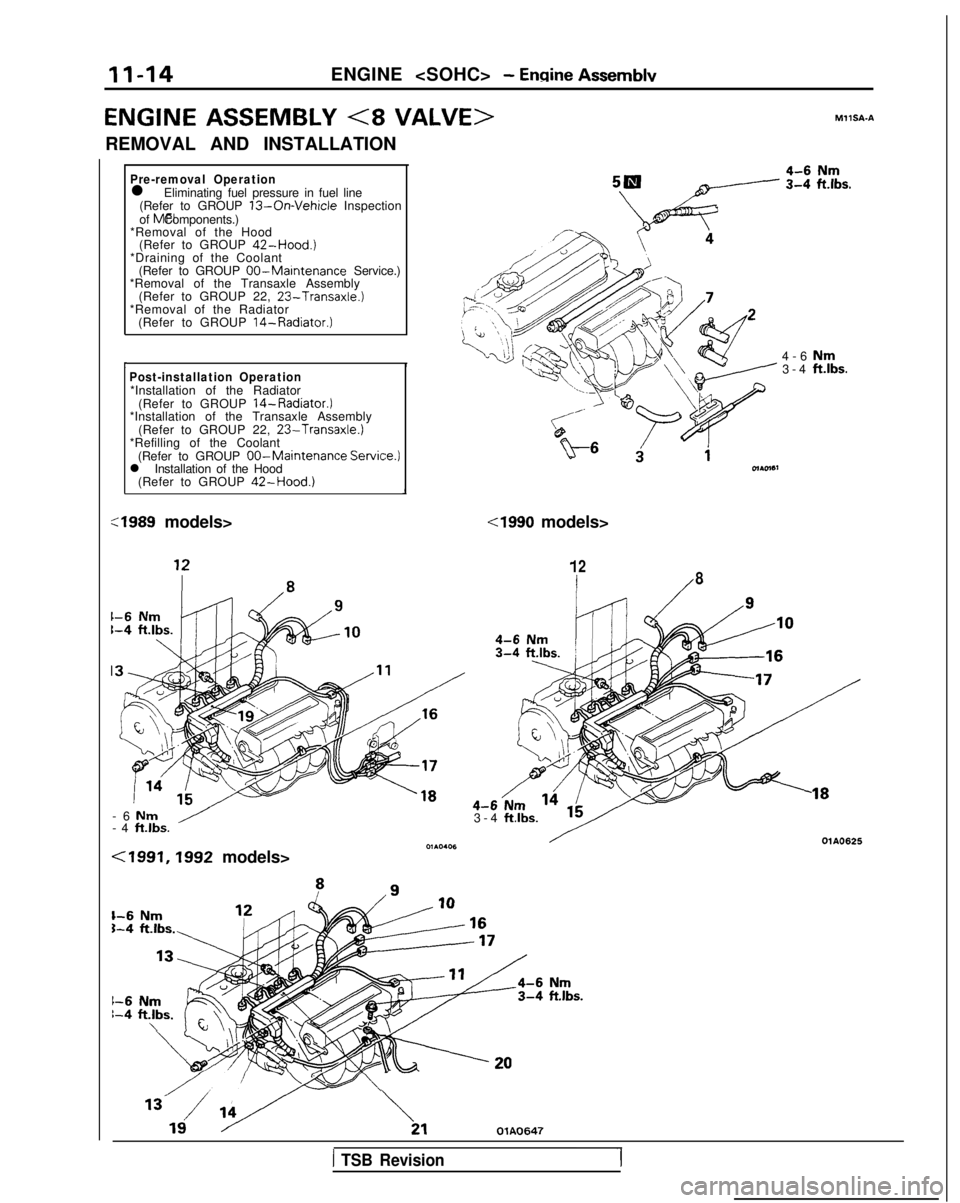
Pre-removal Operationl Eliminating fuel pressure in fuel line
(Refer to GROUP 13-On-Vehicle Inspection
of MFI Components.)
*Removal of the Hood (Refer to GROUP
42-Hood.)*Draining of the Coolant
(Refer to GROUP OO-Maintenance Service.)
*Removal of the Transaxle Assembly
(Refer to GROUP 22,
23-Transaxle.)*Removal of the Radiator(Refer to GROUP 14-Radiator.)
I IPost-installation Operation*Installation of the Radiator
(Refer to GROUP 14-Radiator.)*Installation of the Transaxle Assembly (Refer to GROUP 22, 23-Transaxle.)*Refilling of the Coolant(Refer to GROUP 00-Maintenance Servic
l Installation of the Hood
(Refer to GROUP
42-Hood.)
:e.) :1989
models>
-6
Nm-4 ft.lbs./
4-6 Nm3-4 ft.lbs.
cl990 models>
128
3-4 ftlbs. MllSA-A
<1991,1992 models>
1-6 Nm5-4 ft.lbs.
1-6 Nm1-4 ft.lbs.\
OlAO625
\,,OlA0647
1 TSB Revision
Page 65 of 1273
ENGINE
35-4
5
25-33 35-45 Nm
25-33
ft.lbs.
24
35-45 N
m
25-33
ft.lbs.
23-2
7
250166309
I23
:l;nbs.
50-65 Nm
36-47 ft.lbs.
dv--iu wm: ’22-29 ft.lbs. \ d.(,(I3L i‘9
50-65 Nm*Cb36-47 ft.lbs.* -
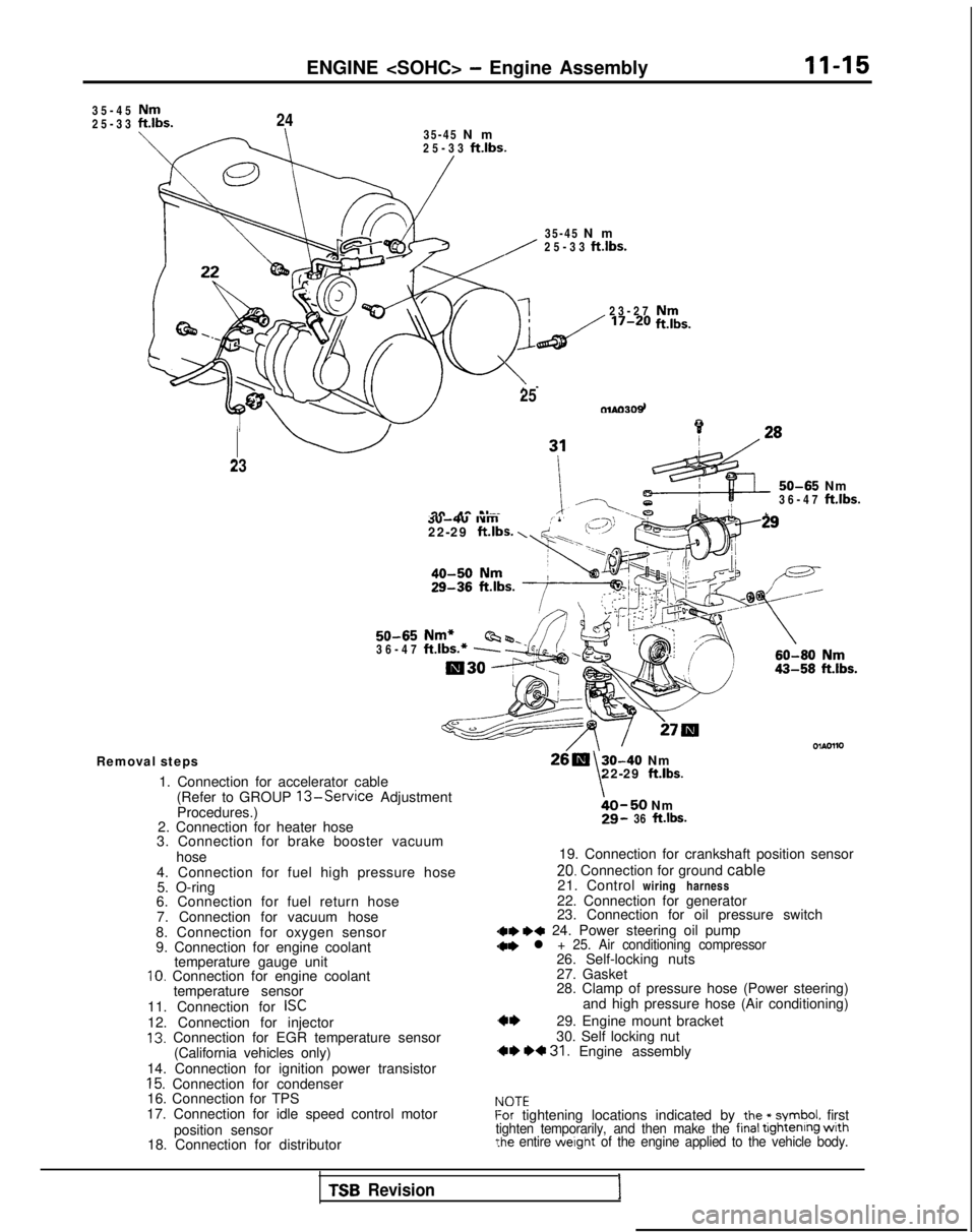
Removal steps
1. Connection for accelerator cable(Refer to GROUP
13-Service Adjustment
Procedures.)
2. Connection for heater hose
3. Connection for brake booster vacuum
hose
4. Connection for fuel high pressure hose 5. O-ring
6. Connection for fuel return hose
7. Connection for vacuum hose
8. Connection for oxygen sensor
9. Connection for engine coolant temperature gauge unit
10. Connection for engine coolant
temperature sensor
11. Connection for
ISC12. Connection for injector13. Connection for EGR temperature sensor (California vehicles only)
14. Connection for ignition power transistor
15. Connection for condenser
16. Connection for TPS
17. Connection for idle speed control motor
position sensor
18. Connection for distributor
30-40 Nm
\22-29 ft.lbs.
bO-50 Nm29- 36 ft.lbs.
19. Connection for crankshaft position sensor
20. Connection for ground cable
21. Control wiring harness
22. Connection for generator
23. Connection for oil pressure switch
dae I)* 24. Power steering oil pump
28. Clamp of pressure hose (Power steering) and high pressure hose (Air conditioning)
29. Engine mount bracket
30. Self locking nut
,** *+ 31. Engine assembly
IdOTEf-or tightening locations indicated by the * symbol. firsttighten temporarily, and then make the final tightenrng wrth?he entire werght of the engine applied to the vehicle body.
TSB Revision1
Page 67 of 1273
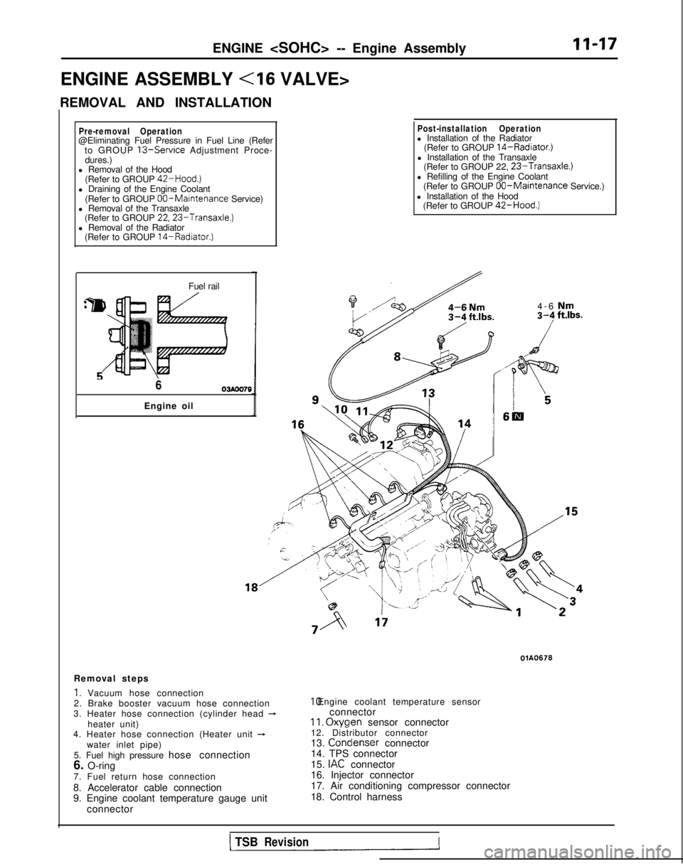
ENGINE
ENGINE ASSEMBLY
REMOVAL AND INSTALLATION
II-17
Pre-removal Operation@Eliminating Fuel Pressure in Fuel Line (Refer to GROUP 13-Service Adjustment Proce-
dures.)
l Removal of the Hood
(Refer to GROUP
42-Hood.)l Draining of the Engine Coolant
(Refer to GROUP 00-Maintenance Service)
l Removal of the Transaxle (Refer to GROUP
22,23-Transaxle.)l Removal of the Radiator(Refer to GROUP 14-Radiator.)
Fuel rail
603AOO70
Engine oil
Post-installation Operationl Installation of the Radiator (Refer to GROUP 14-Radiator.)l Installation of the Transaxle(Refer to GROUP 22, 23-Transaxle.)l Refilling of the Engine Coolant
(Refer to GROUP 00-Maintenance Service.)
l Installation of the Hood (Refer to GROUP
42-Hood.)
4-6 Nm3-F ft.lbs.
I6m
Removal steps
1. Vacuum hose connection
2. Brake booster vacuum hose connection
3. Heater hose connection (cylinder head
-heater unit)
4. Heater hose connection (Heater unit +water inlet pipe)
5. Fuel high pressure hose connection
6. O-ring
7. Fuel return hose connection
8. Accelerator cable connection
9. Engine coolant temperature gauge unit connector
OlA0676 10. Engine coolant temperature sensor
connector
II. Oxyqen
sensor connector
12. Distributor connector
13. Condenser
connector
14. TPS connector
15.
IAC connector
16. Injector connector
17. Air conditioning compressor connector
18. Control harness
1 TSBRevisionI
Page 75 of 1273
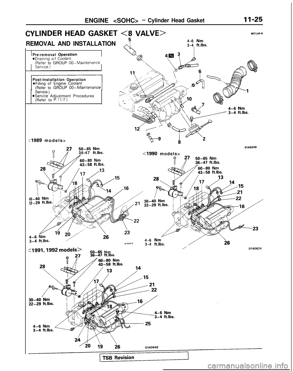
ENGINE
CYLINDER HEAD GASKET <8 VALVE>
REMOVAL AND INSTALLATION,,j4-6 Nm3-4 ft.lbs.
MllJA-A
Pre-removal ODeration
eDraInIng
of Coolant (Refer
to GROUP OO-Maintenance
Post-installation Operation
(Refer to GROUP 00-MaintenanceService.)@Service Adjustment Procedures
(Refer to P.ll-7.)
:1989 models
>
50-65
Nm36-47 ftlbs.
OlAO310
cl990 models>
4-6
Nm3-4 ftlbs.
:1991,1992 models>/OlA0624 50-65
Nm
Page 76 of 1273
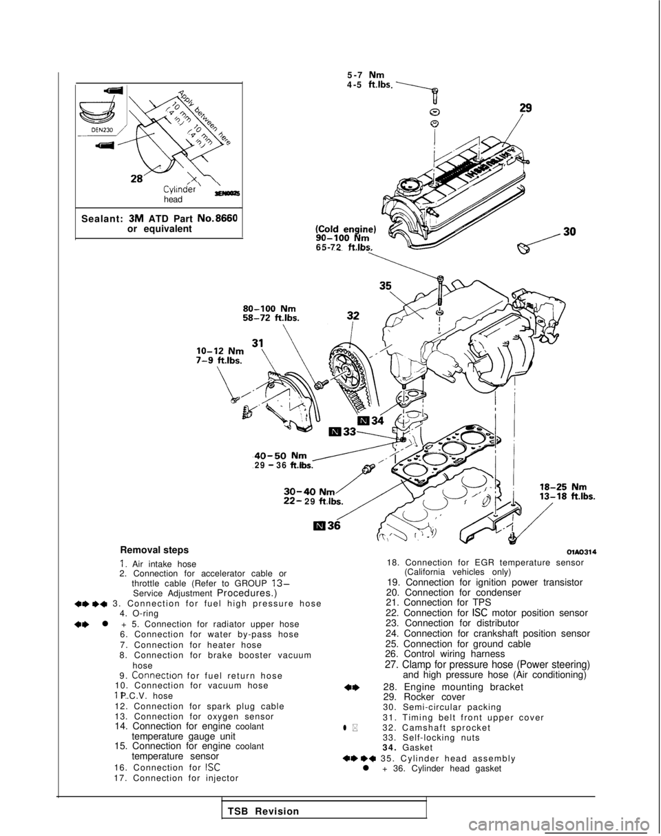
Cyl1n&r’ ;;(oozhead
Sealant: 3M
ATD Part No.8660
or equivalent 5-7
Nm4-5 ft.lbs 90-100
Nm65-72 ftlbs.
40-50 Nm /29 - 36 ft.lbs.
30-40 Nm22- 29
ftlbs.
Removal steps
I. Air intake hose
2. Connection for accelerator cable or
throttle cable (Refer to GROUP
13-Service Adjustment Procedures.)+e +a 3. Connection for fuel high pressure hos
e
4. O-ring
+e l + 5. Connection for radiator upper hose
6. Connection for water by-pass hose
7. Connection for heater hose
8. Connection for brake booster vacuum
hose
9.
Connectron for fuel return hos
e
10. Connection for vacuum hose 11. P.C.V. hose
12. Connection for spark plug cable
13. Connection for oxygen sensor
14. Connection for engine coolant temperature gauge unit
15. Connection for engine coolant
temperature sensor
16. Connection for
ISC17. Connection for injector
olAo314
l *
18. Connection for EGR temperature sensor (California vehicles only)
19. Connection for ignition power transistor
20. Connection for condenser
21. Connection for TPS
22. Connection for
ISC motor position sensor
23. Connection for distributor
24. Connection for crankshaft position sensor
25. Connection for ground cable
26. Control wiring harness
27. Clamp for pressure hose (Power steering)and high pressure hose (Air conditioning)
28. Engine mounting bracket
29. Rocker cover
30. Semi-circular packing
31. Timing belt front upper cover
32. Camshaft sprocket 33. Self-locking nuts
34. Gasket
+e ++ 35. Cylinder head assembl
y
l + 36. Cylinder head gasket
TSB Revision