1989 MITSUBISHI GALANT brake sensor
[x] Cancel search: brake sensorPage 41 of 1273
GENERAL - Scheduled Maintenance Table/Maintenance Service00-39
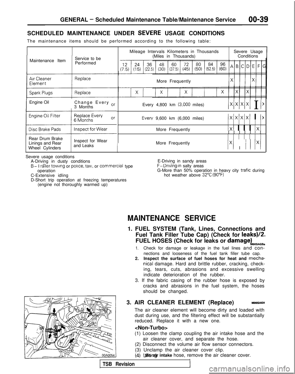
SCHEDULED MAINTENANCE UNDER SEVEiRE USAGE CONDITIONS
The maintenance items should be performed according to the following tab\
le:
Maintenance Item Service to be
Performed
IEngine Oil Change Every or
3 Months
(:z:.:a::I
Rear Drum Brake
Linings and Rear
Wheel Cylinders Inspect for Wear
and Leaks
1
Mileage Intervals Kilometers in Thousands (Miles in Thousands) Severe Usage
Conditions
More Frequently
Every 4,800 km
(3,000 miles)/xlxlx/xI I I1 Every
9,600 km (6,000 miles)
IxIxlxIxI I I>(
More Frequently1x1 I I I 1x1I I I I I I I
More Frequently
Ix1 I I I lx/
Severe usage conditions A-Driving in dusty conditions
- -B- I railer
towing or police.
taxi,
or commercial
type
operation
C-Extensive idling
D-Short trip operation at freezing temperatures (engine not thoroughly warmed up) E-Driving in sandy areas- -..F-Dnvlng In salty areas
G-More than 50% operation in heavy city trafic during
hot weather above 32°C (90°F)
MAINTENANCE SERVICE
1. FUEL SYSTEM (Tank, Lines, Connections and
Fuel Tank Filler Tube Cap) (Check for leaks)/2.
FUEL HOSES (Check for leaks or
damagekOOSnOB.
1.Check for damage or leakage in the fuel lines and con-
nections and looseness of the fuel tank filler tube cap.
2. Inspect the surface of fuel hoses for heat and mecha-
nicall damage. Hard and brittle rubber, cracking, check-
ing, tears, cuts, abrasions and excessive swelling
indicate deterioration of the rubber.
3. If the fabric casing of the rubber hose is exposed by cracks and abrasions in the fuel system, the hoses
should be changed.
3. AIR CLEANER ELEMENT (Replace)
MMlSAKH
The air cleaner element will become dirty and loaded with dust during use, and the filtering effect will be substantiallyreduced. Replace it with a new one.
(1) Loosen the clamp coupling the air intake hose and the air cleaner cover, and separate the hose.
(2) Disconnect the volume air flow sensor connectors.
(3) Unclamp the air cleaner cover clip.
(4) Lifting the air intake hose, remove the air cleaner cover.
TSB Revision1
Page 65 of 1273
ENGINE
35-4
5
25-33 35-45 Nm
25-33
ft.lbs.
24
35-45 N
m
25-33
ft.lbs.
23-2
7
250166309
I23
:l;nbs.
50-65 Nm
36-47 ft.lbs.
dv--iu wm: ’22-29 ft.lbs. \ d.(,(I3L i‘9
50-65 Nm*Cb36-47 ft.lbs.* -
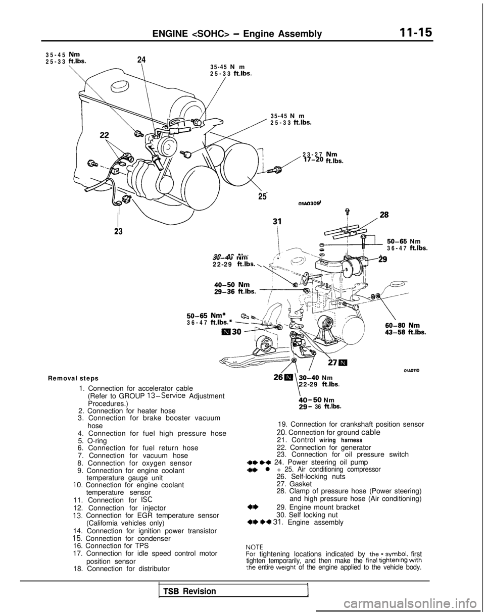
Removal steps
1. Connection for accelerator cable(Refer to GROUP
13-Service Adjustment
Procedures.)
2. Connection for heater hose
3. Connection for brake booster vacuum
hose
4. Connection for fuel high pressure hose 5. O-ring
6. Connection for fuel return hose
7. Connection for vacuum hose
8. Connection for oxygen sensor
9. Connection for engine coolant temperature gauge unit
10. Connection for engine coolant
temperature sensor
11. Connection for
ISC12. Connection for injector13. Connection for EGR temperature sensor (California vehicles only)
14. Connection for ignition power transistor
15. Connection for condenser
16. Connection for TPS
17. Connection for idle speed control motor
position sensor
18. Connection for distributor
30-40 Nm
\22-29 ft.lbs.
bO-50 Nm29- 36 ft.lbs.
19. Connection for crankshaft position sensor
20. Connection for ground cable
21. Control wiring harness
22. Connection for generator
23. Connection for oil pressure switch
dae I)* 24. Power steering oil pump
28. Clamp of pressure hose (Power steering) and high pressure hose (Air conditioning)
29. Engine mount bracket
30. Self locking nut
,** *+ 31. Engine assembly
IdOTEf-or tightening locations indicated by the * symbol. firsttighten temporarily, and then make the final tightenrng wrth?he entire werght of the engine applied to the vehicle body.
TSB Revision1
Page 67 of 1273
ENGINE
ENGINE ASSEMBLY
REMOVAL AND INSTALLATION
II-17
Pre-removal Operation@Eliminating Fuel Pressure in Fuel Line (Refer to GROUP 13-Service Adjustment Proce-
dures.)
l Removal of the Hood
(Refer to GROUP
42-Hood.)l Draining of the Engine Coolant
(Refer to GROUP 00-Maintenance Service)
l Removal of the Transaxle (Refer to GROUP
22,23-Transaxle.)l Removal of the Radiator(Refer to GROUP 14-Radiator.)
Fuel rail
603AOO70
Engine oil
Post-installation Operationl Installation of the Radiator (Refer to GROUP 14-Radiator.)l Installation of the Transaxle(Refer to GROUP 22, 23-Transaxle.)l Refilling of the Engine Coolant
(Refer to GROUP 00-Maintenance Service.)
l Installation of the Hood (Refer to GROUP
42-Hood.)
4-6 Nm3-F ft.lbs.
I6m
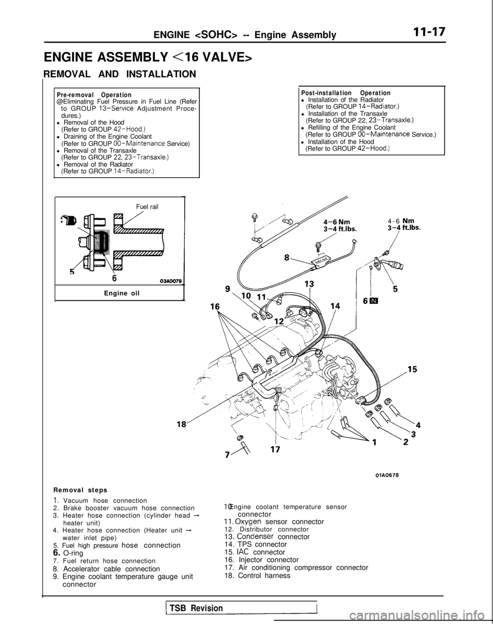
Removal steps
1. Vacuum hose connection
2. Brake booster vacuum hose connection
3. Heater hose connection (cylinder head
-heater unit)
4. Heater hose connection (Heater unit +water inlet pipe)
5. Fuel high pressure hose connection
6. O-ring
7. Fuel return hose connection
8. Accelerator cable connection
9. Engine coolant temperature gauge unit connector
OlA0676 10. Engine coolant temperature sensor
connector
II. Oxyqen
sensor connector
12. Distributor connector
13. Condenser
connector
14. TPS connector
15.
IAC connector
16. Injector connector
17. Air conditioning compressor connector
18. Control harness
1 TSBRevisionI
Page 76 of 1273
Cyl1n&r’ ;;(oozhead
Sealant: 3M
ATD Part No.8660
or equivalent 5-7
Nm4-5 ft.lbs 90-100
Nm65-72 ftlbs.
40-50 Nm /29 - 36 ft.lbs.
30-40 Nm22- 29
ftlbs.
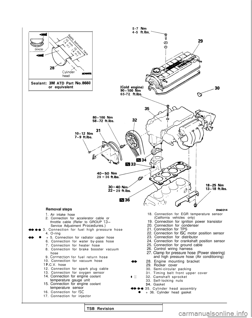
Removal steps
I. Air intake hose
2. Connection for accelerator cable or
throttle cable (Refer to GROUP
13-Service Adjustment Procedures.)+e +a 3. Connection for fuel high pressure hos
e
4. O-ring
+e l + 5. Connection for radiator upper hose
6. Connection for water by-pass hose
7. Connection for heater hose
8. Connection for brake booster vacuum
hose
9.
Connectron for fuel return hos
e
10. Connection for vacuum hose 11. P.C.V. hose
12. Connection for spark plug cable
13. Connection for oxygen sensor
14. Connection for engine coolant temperature gauge unit
15. Connection for engine coolant
temperature sensor
16. Connection for
ISC17. Connection for injector
olAo314
l *
18. Connection for EGR temperature sensor (California vehicles only)
19. Connection for ignition power transistor
20. Connection for condenser
21. Connection for TPS
22. Connection for
ISC motor position sensor
23. Connection for distributor
24. Connection for crankshaft position sensor
25. Connection for ground cable
26. Control wiring harness
27. Clamp for pressure hose (Power steering)and high pressure hose (Air conditioning)
28. Engine mounting bracket
29. Rocker cover
30. Semi-circular packing
31. Timing belt front upper cover
32. Camshaft sprocket 33. Self-locking nuts
34. Gasket
+e ++ 35. Cylinder head assembl
y
l + 36. Cylinder head gasket
TSB Revision
Page 80 of 1273
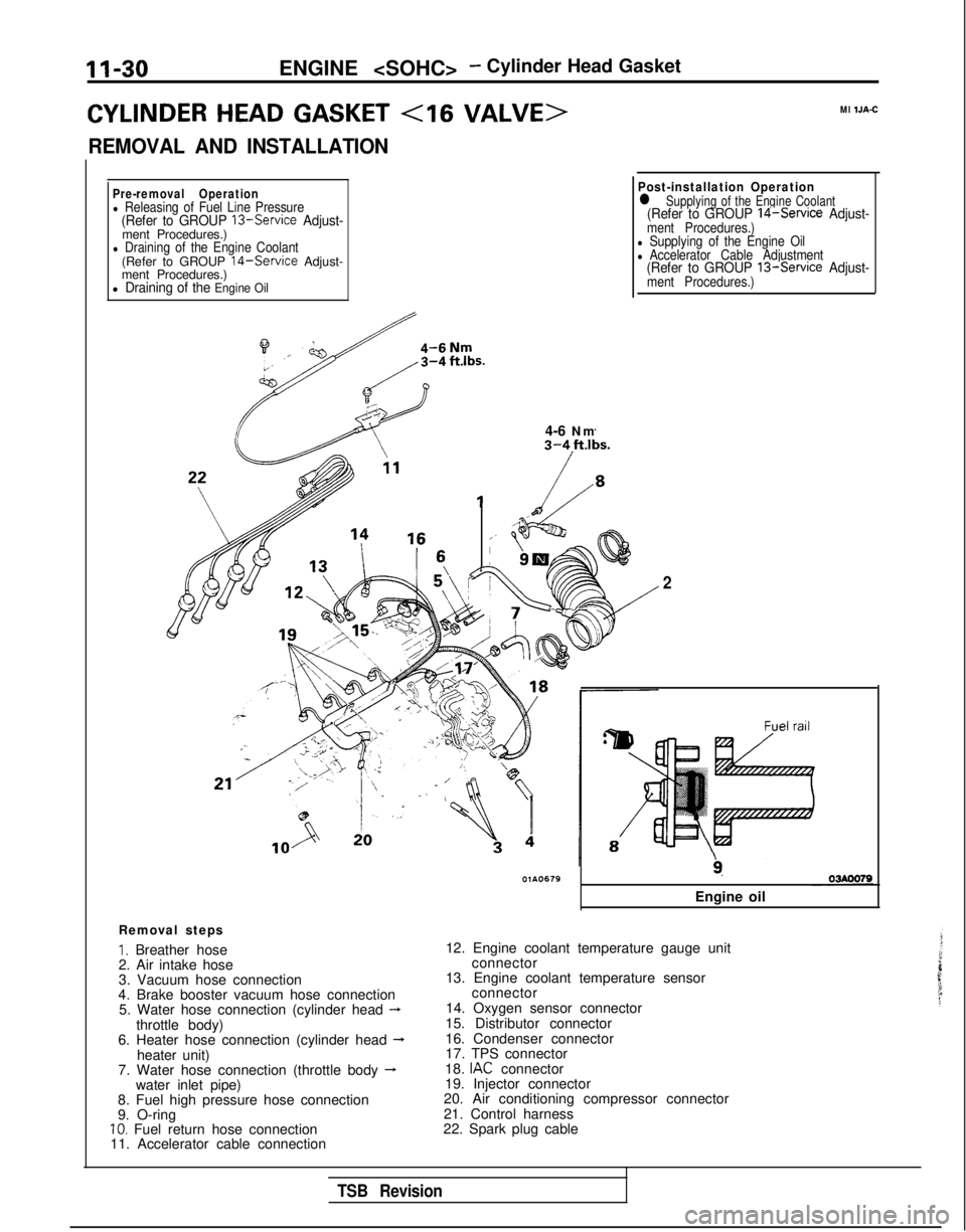
II-30ENGINE
CYLINDER HEAD GASKET
REMOVAL AND INSTALLATION
Ml IJA-C
Pre-removal Operationl Releasing of Fuel Line Pressure(Refer to GROUP 13-Service Adjust-ment Procedures.)l Draining of the Engine Coolant(Refer to GROUP 14-Service Adjust-
ment Procedures.)
l Draining of the Engine Oil
il4-6 Nm
Post-installation Operationl Supplying of the Engine Coolant(Refer to GROUP 14-Service Adjust-ment Procedures.)l Supplying of the Engine Oill Accelerator Cable Adjustment(Refer to GROUP 13-Service Adjust-ment Procedures.)
Removal steps
I. Breather hose
2. Air intake hose
3. Vacuum hose connection
4. Brake booster vacuum hose connection 5. Water hose connection (cylinder head
-throttle body)
6. Heater hose connection (cylinder head --Lheater unit)
7. Water hose connection (throttle body -water inlet pipe)
8. Fuel high pressure hose connection
9. O-ring
10. Fuel return hose connection
11. Accelerator cable connection
2
9.
Engine oil
12. Engine coolant temperature gauge unit connector
13. Engine coolant temperature sensor connector
14. Oxygen sensor connector
15. Distributor connector
16. Condenser connector
17. TPS connector
18.
IAC connector
19. Injector connector
20. Air conditioning compressor connector
21. Control harness
22. Spark plug cable
TSB Revision
Page 123 of 1273
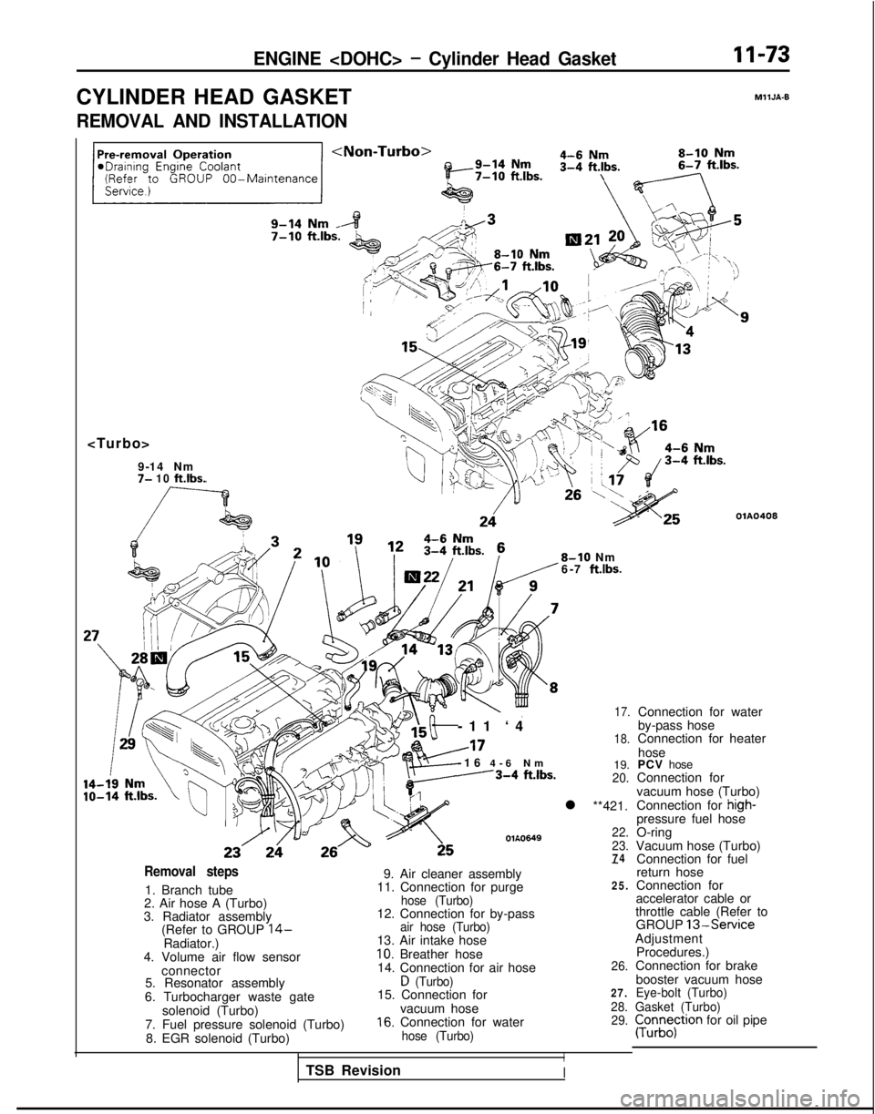
ENGINE
CYLINDER HEAD GASKET
MllJA-9
REMOVAL AND INSTALLATION
7- 10 ft.lbs.
OlA0408
8-10 Nm
6-7 ft.lbs.
-11 ‘
4
A17
-16
4-6 N
m
---3-4
ftlbs.
OlA0649
17.
18.
19.20.
l **421.
22.
23.
74Removal steps
1. Branch tube
2. Air hose A (Turbo)
3. Radiator assembly (Refer to GROUP
14-Radiator.)
4. Volume air flow sensor
connector
5. Resonator assembly
6. Turbocharger waste gate solenoid (Turbo)
7. Fuel pressure solenoid (Turbo) 8. EGR solenoid (Turbo)
-
9. Air cleaner assembly
11. Connection for purge25.
hose (Turbo)12. Connection for by-passair hose (Turbo)13. Air intake hose10. Breather hose
14. Connection for air hose26.
D (Turbo)15. Connection for27.
vacuum hose28.
16. Connection for water29.
hose (Turbo)
I
Connection for water
by-pass hose
Connection for heater
hose
PCV hose
Connection for
vacuum hose (Turbo)
Connection for
high-pressure fuel hose
O-ring
Vacuum hose (Turbo) Connection for fuel
return hose
Connection for
accelerator cable or
throttle cable (Refer to GROUP
13-ServiceAdjustment
Procedures.)
Connection for brake
booster vacuum hose
Eye-bolt (Turbo)
Gasket (Turbo)
pun;;;tron for oil pipe
TSB Revision
I
Page 207 of 1273
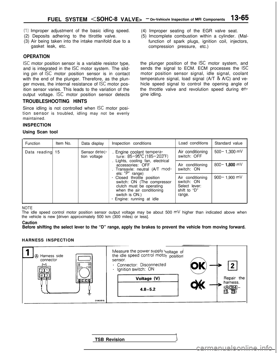
FUEL SYSTEM
(1) Improper adjustment of the basic idling speed.
(2) Deposits adhering to the ttirottle valve.
(3) Air being taken into the intake manifold due to a gasket leak, etc.
OPERATION
ISC motor position sensor is a variable resistor type,
and is integrated in the
ISC motor system. The slid-
ing pin of
ISC motor position sensor is in contact
with the end of the plunger. Therefore, as the plun- ger moves, the internal resistance of
ISC motor pos-
ition sensor varies. This leads to the variation of the (4) Improper seating of the EGR valve seat.
(5) lmcomplete combustion within a cylinder. (Mal-
function of spark plugs, ignition coil, injectors,
compression pressure, etc.)
the plunger position of the
ISC motor system, and
sends the signal to ECM. ECM processes the
ISC
motor position sensor signal, idle signal, coolant
temperature signal, load signal (A/T &
A/C) and ve-
hicle speed signal to control the opening angle of
the throttle valve and revolution speed during
en-
output voltage. ISC motor position sensor detects gine idling.
TROUBLESHOOTING HINTS
Since idling is not controlled when ISC motor posi-
tion sensor is troubled, idling may not be evenly
maintained.
INSPECTION
Using Scan tool
FunctionItem No. Data display Inspection conditions Load conditions
Standard value
Data reading 15 Sensor detec-
. Engine coolant tempera-
Air conditioning 500- 1,300 mV
tion voltage
ture: 85-95’C (185-203°F)
switch: OFF
. Lights, cooling fan, electrical accessories: OFF Air conditioning 800-
1,800 mV. Transaxle: neutral (A/T
mod-
switch: ON
els: “P”
range)
1 Closed throttle position Air conditioning900- 1,900 mVswitch: ON (The compressorswitch: ON
clutch must be operating Select lever:
when the air conditioning shift to “D”
switch is ON.)
range.* Engine: running at idle
NOTEThe idle speed control motor position sensor output voltage may be about\
500 mV higher than indicated above when
the vehicle is new [driven approximately 500 km (300 miles) or less].
CautionBefore shifting the select lever to the “D” range, apply the brake\
s to prevent the vehicle from moving forward.
HARNESS INSPECTION
Measure the power supply voltage of
the idle speed control motor position
ei;;;it;;sco$ected
__...._ -.-
TSB Revision
Page 305 of 1273
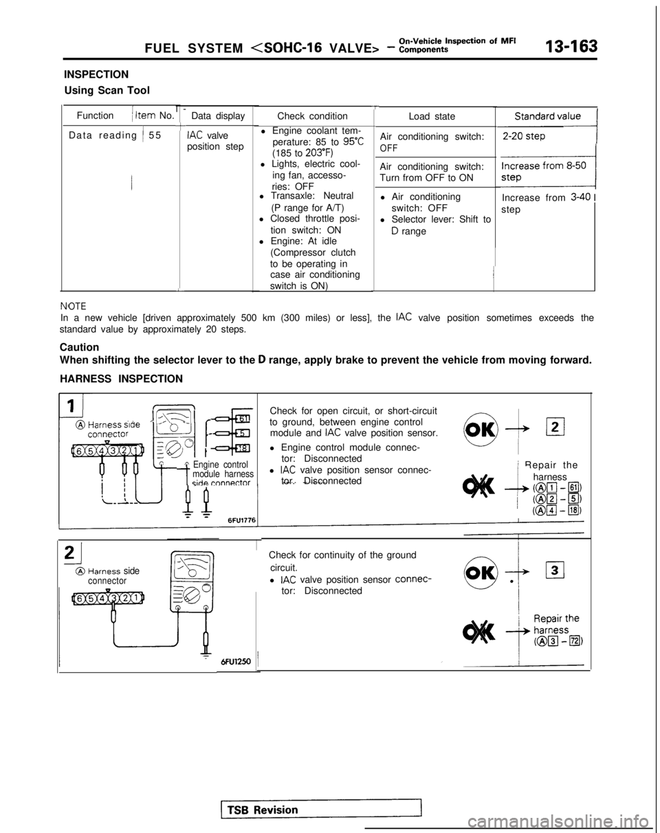
FUEL SYSTEM
INSPECTION
Using Scan Tool
Function
( Item No.
Data reading
/ 5
5
l-
+
L
Data display
IAC valve
position step
TCheck condition
l Engine coolant tem- perature: 85 to
95°C
(185 to 203’F)l Lights, electric cool- ing fan, accesso-
ries: OFF
l Transaxle: Neutral
(P range for A/T)
l Closed throttle posi-
tion switch: ON
l Engine: At idle
(Compressor clutch
to be operating in case air conditioning
switch is ON) Load state
Air conditioning switch:
OFF
Air conditioning switch:
Turn from OFF to ON l Air conditioning switch: OFF
l Selector lever: Shift to
D range
,,,,,,,,,I
Increase from 3-40 I
step
NfOTE
In a new vehicle [driven approximately 500 km (300 miles) or less], th\
e IAC valve position sometimes exceeds the
standard value by approximately 20 steps.
Caution
When shifting the selector lever to the
D range, apply brake to prevent the vehicle from moving forward.
HARNESS INSPECTION
IIL\-11 r@Harm ” ’ -conna
tA Engine control
-tmodule harnessside rnnnnctor
Check for open circuit, or short-circuit
to ground, between engine control module and
IAC valve position sensor.
l Engine control module connec- tor: Disconnected
l
IAC valve position sensor connec-
tor. Disconnected
21
@Harness sideconnector
0,OK-& 121
i Repair the
--L
harness
(@lcl- El)
/ ml-~) (@pJ
- @I)
Check for continuity of the ground
circuit.
l
IAC valve position sensor connec-
tor: Disconnected