Page 740 of 1273
23-34AUTOMATIC TRANSAXLE - Troubleshooting
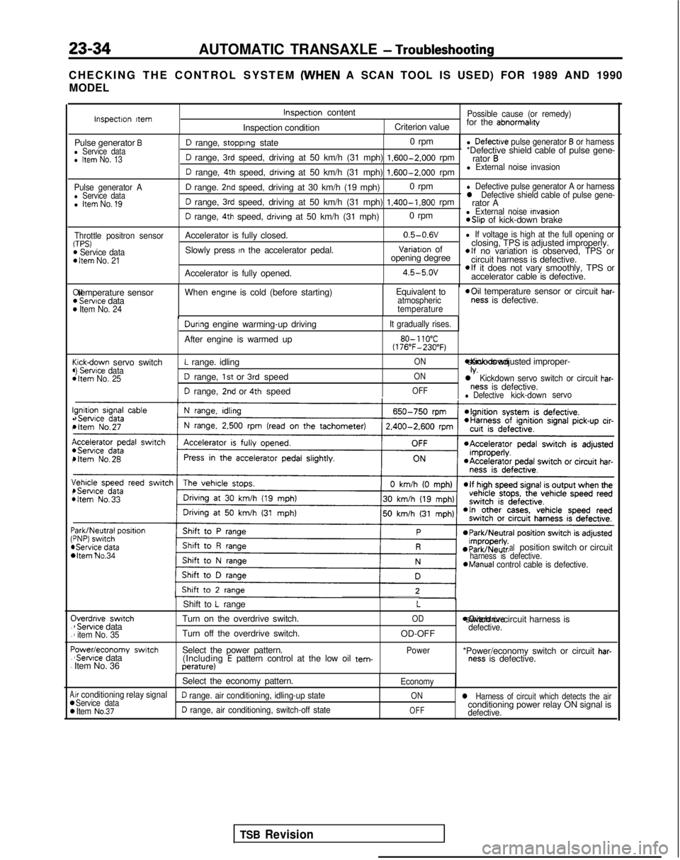
CHECKING THE CONTROL SYSTEM (WHEN
A SCAN TOOL IS USED) FOR 1989 AND 1990
MODEL
Pulse generator Al Service datal Item No. 1’9
Throttle positron sensorTPS)m Service dataD Item No. 21
I!(
(44
c44
I!.,
I(,
\,4
:44 C
.
.
F.
.
A00
D range, stopprng state 0 rpml Defectrve pulse generator B or harness
D range, 3rd speed, driving at 50 km/h (31 mph) 1.600-2.000
rpm*Defective shield cable of pulse gene-
rator B
D range, 4th speed, drivrng at 50 km/h (31 mph) 1.600-2.000
rpml External noise invasion
D range. 2nd speed, driving at 30 km/h (19 mph) 0 rpml Defective pulse generator A or harness
D range, 3rd speed, driving at 50 km/h (31 mph) 1.400-1.800
rpml Defective shield cable of pulse gene-rator A
D range, 4th speed, drivrng at 50 km/h (31 mph) 0 rpml External noise Invasion *Slip
of kick-down brake
Accelerator is fully closed. 0.5-0.6V
l If voltage is high at the full opening or
Slowly press In the accelerator pedal.Variatron of
closing, TPS is adjusted improperly.
opening degreeelf no variation is observed, TPS or
circuit harness is defective.
Accelerator is fully opened.
4.5-5.ovelf it does not vary smoothly, TPS or
accelerator cable is defective. Xl temperature sensor
) Servtce data) Item No. 24
When engtne is cold (before starting)
Equivalent toatmospheric
temperature *Oil
temperature sensor or circuit har-ness is defective.
cickdown servo switch) Servrce data1 Item No. 25
Durrng engine warming-up driving
After engine is warmed up
L range. idling
D range, 1st or 3rd speed
D range, 2nd or 4th speed
It gradually rises.
80- 110°C(176”F-230°F)
ON *Kick-down servo IS adjusted improper-
ONIV.l Kickdown servo switch or circuit har-
OFFness is defective.l Defectivekick-down
servo
bItem No.34 alposition switch or circuitharness is defective.*Manual
control cable is defective.
Iverdnve switch1 Servrce data1 item No. 35
‘owedeconomy swatch‘Servrce data
Item No. 36 Shift to
L range
Turn on the overdrive switch.
Turn off the overdrive switch.
Select the power pattern. (Including
E pattern control at the low oil tem-perature)
L
OD
OD-OFF
Power moverdrive switch or circuit harness is
defective.
*Power/economy switch or circuit har-ness is defective.
Select the economy pattern.
Economy
.ir conditioning relay signalService dataD range. air conditioning, idling-up stateONl Harness of circuit which detects the air
Item No.37D range, air conditioning, switch-off stateOFFconditioning power relay ON signal isdefective.
Inspectron ttemInspectron content
Inspection conditionPossible cause (or remedy)
Criterion value for the abnormalrty
Pulse generator Bl Service datal Item No. 13
TSB Revision
Page 798 of 1273
23-92AUTOMATIC TRANSAXLE - Service Adjustment Procedures
NOTE
When adjusting the reducing pressure, aim for the center
value (425 kPa, 60 psi) of the standard value allowance.
Standard value: 415-435
kPa (59-62 psi)
Oil pressure change for each turn of adjustment screw: 22
kPa (3.1 psi) . . . FWD (Up to MODEL 1990)
45
kPa (6.4 psi) . . . FWD (From MODEL 1990.5, AWD)
3. Install the oil filter and oil pan in the same way as for adjustment of the line pressure.
4. Make the oil pressure test. Readjust if necessary.
(If the scan tool is used)
1. Using the scan tool, forcibly drive the pressure control
solenoid valve at 50% duty, and measure the kick-down
brake apply pressure.
If the kick-down brake apply pressure does not exist within
the standard value width, adjust the pressure with the
reducing pressure adjustment screw.
Standard value: 275 + 10 kPa (39 + 1 psi)
Oil pressure change for each turn of adjustment screw:
25 kPa (3.6 psi) FWD (Up to MODEL 1990)
22
kPa (3.1 psi) FWD (From MODEL 1990.5), AWD
2. Check to be sure that the reducing pressure (after the
adjustment is completed) is within the range of 360-480
kPa (51 -68 psi.).
Caution
This adjustment should be made at an oil
temperature
of 70- 80°C
(160- 180°F).
If the adjustment is made at a temperature that is too
high, the line pressure will drop during idling, with the
result that it might not be possible to make the correct
adjustment.
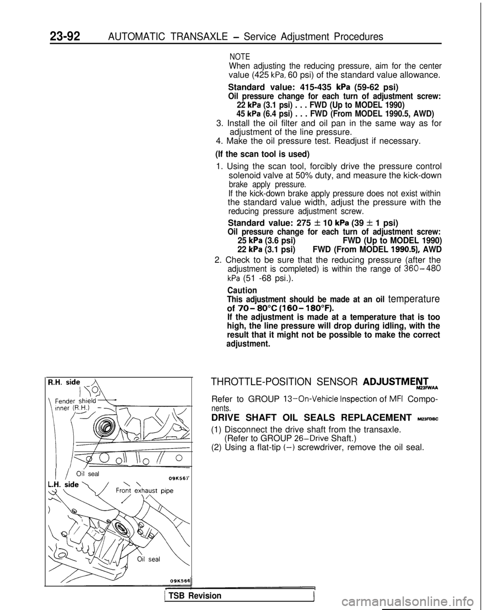
I / Oii
seal09K561
THROTTLE-POSITION SENSOR ADJUSTMEF&
Refer to GROUP 13-On-Vehicle Inspection of MFI Compo-
nents.
DRIVE SHAFT OIL SEALS REPLACEMENT MZ3FDBC
(1) Disconnect the drive shaft from the transaxle. (Refer to GROUP 26-Drive
Shaft.)
(2) Using a flat-tip
(-) screwdriver, remove the oil seal.
1 TSB Revision1
Page 836 of 1273
26-6FRONT AXLE -Hub and Knuckle
HUB AND
KNUCKLE
REMOVAL AND INSTALLATION
SO-105 Nm
65-76 ft.lbs.
Vehicles with ACTIVE-ECS*’
80-100 Nm’\58-72 ftlbs.
9-14 Nm7- 10 ft.lbs.I
I
5rq :I
u
- 4. .i,'-
B860-72 Nm200-‘260 Nm
43-52
ft.lbs.IU-188 ft.lbs.
llA0121
Removal steps
l +1. Cotter pin
+e I)+ 2. Drive shaft nut
l + 3. Washer
a*4. Front speed sensor connection< Vehicules
with A.B.S.*‘> (Refer toGROUP 35-Speed sensor)a*5. Caliper assembly
6. Brake disc
7. Front height sensor connection
(Refer to GROUP 33B-Height sensor)
8. Self locking nut
+e ~~9. Lower arm ball joint connection
10. Cotter pin
::11. Tie rod end connection
12. Drive shaft
13. Front strut mounting bolt
14. Hub and knuckle
NOTE
::: Anti-lock braking system: ACTIVE-Electronic Control Suspension
TSB Revision
Page 837 of 1273
FRONT AXLE - Hub and Knuckle26-7
SERVICE POINTS OF REMOVALM261sAE
2.
4.
REMOVAL OF DRIVE SHAFT NUTLoosen the drive shaft nut while the vehicle is on the floor
with the brakes applied.
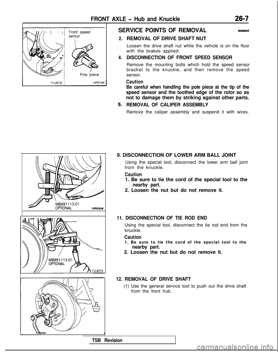
DISCONNECTION OF FRONT SPEED SENSOR
Remove the mounting bolts which hold the speed sensor
bracket to the knuckle, and then remove the speed
sensor.
Caution
Be careful when handling the pole piece at the tip of the
speed sensor and the toothed edge of the rotor so as
not to damage them by striking against other parts.
REMOVAL OF CALIPER ASSEMBLY
Remove the caliper assembly and suspend it with wires.
9. DISCONNECTION OF LOWER ARM BALL JOINT Using the special tool, disconnect the lower arm ball joint
from the knuckle.
Caution
1. Be sure to tie the cord of the special tool to the
nearby part.
2. Loosen the nut but do not remove it.
11. DISCONNECTION OF TIE ROD END
Using the special tool, disconnect the tie rod end from the
knuckle.
Caution
1. Be sure to tie the cord of the special tool to the
nearby part.
2. Loosen the nut but do not remove it.
12. REMOVAL OF DRIVE SHAFT
(1) Use the general service tool to push out the drive shaft from the front hub.
l\\11RO101 1
TSB Revision
Page 843 of 1273
FRONT AXLE - Drive Shaft2643
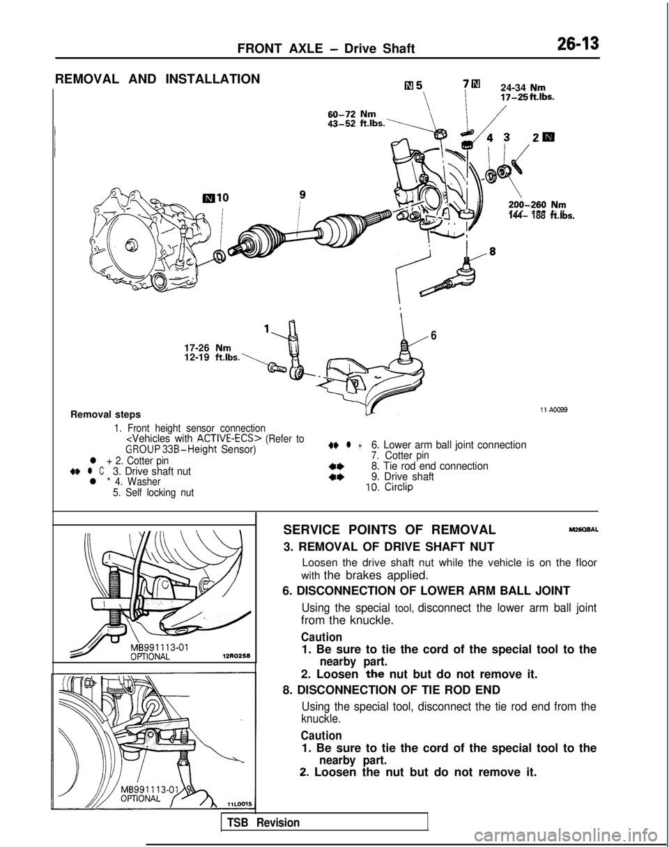
REMOVAL AND INSTALLATION
7m
24-34 Nm 17-25ft.Ibs.
144- 188ft.lbs.
6
17-26 Nm12-19 ft.lbs.
Removal steps11 A0099
1. Front height sensor connection
(Refer toGROUP33B-Height Sensor)
l + 2. Cotter pin+e l C3. Drive shaft nutl * 4. Washer
5. Self locking nut
4I) l +6. Lower arm ball joint connection7.Cotterpin
4+8. Tie rod end connection
4*9. Drive shaft10.Circlip
12R0258
SERVICE POINTS OF REMOVALM280BAL
3. REMOVAL OF DRIVE SHAFT NUT
Loosen the drive shaft nut while the vehicle is on the floor
with the brakes applied.
6. DISCONNECTION OF LOWER ARM BALL JOINT
Using the special tool, disconnect the lower arm ball joint
from the knuckle.
Caution
1. Be sure to tie the cord of the special tool to the
nearby part.
2. Loosen ~the nut but do not remove it.
8. DISCONNECTION OF TIE ROD END
Using the special tool, disconnect the tie rod end from the
knuckle.
Caution
1. Be sure to tie the cord of the special tool to the
nearby part.
2. Loosen the nut but do not remove it.
TSB Revision
Page 862 of 1273
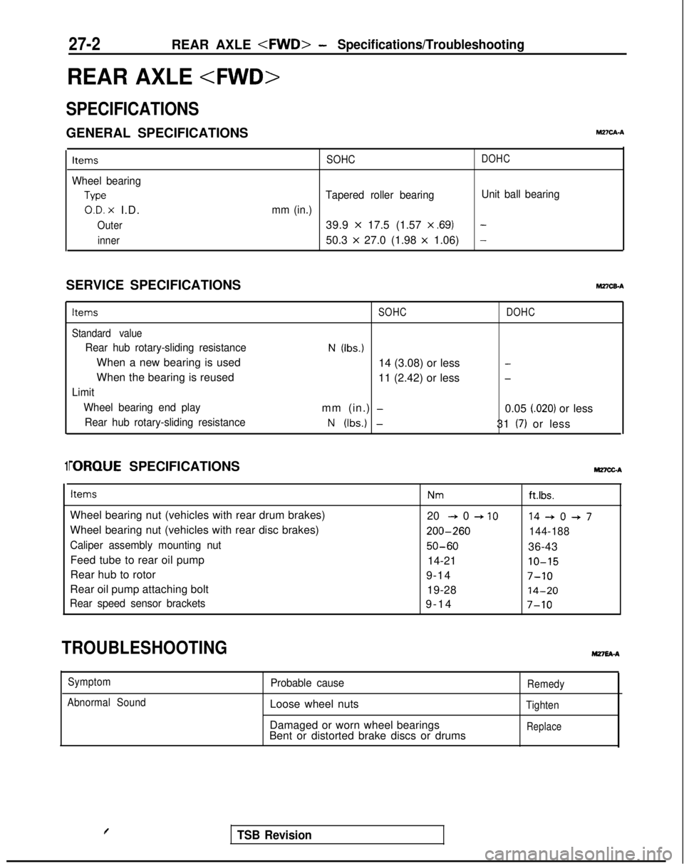
27-2REAR AXLE - Specifications/Troubleshooting
REAR AXLE
SPECIFICATIONS
GENERAL SPECIFICATIONSM2?CA-A
Items
Wheel bearing
Type
O.D. x I.D.
Outer
inner SOHC
DOHC
Tapered roller bearing
Unit ball bearing
mm (in.)
39.9 x 17.5 (1.57 x ,691-
50.3 x 27.0 (1.98 x 1.06)-
SERVICE SPECIFICATIONShl27CEA
Items
Standard value
Rear hub rotary-sliding resistance
When a new bearing is used
When the bearing is reused
Limit Wheel bearing end playRear hub rotary-sliding resistance
SOHC
N (Ibs.)
14 (3.08) or less
11 (2.42) or less
mm (in.)
-
N (Ibs.) -
DOHC
-
-
0.05 i.020) or less
31
(7) or less
1i-ORQUE SPECIFICATIONS MnCGA
Items
Wheel bearing nut (vehicles with rear drum brakes)
Wheel bearing nut (vehicles with rear disc brakes)
Caliper assembly mounting nut
Feed tube to rear oil pump
Rear hub to rotor
Rear oil pump attaching bolt
Rear speed sensor brackets
Nmft.lbs.
20 + 0 + IO14+0+7 200-260
144-188
50-6036-43
14-21
IO-15
9-147-10
19-2814-20
9-1
4
7-10
TROUBLESHOOTINGM27EA-A
Symptom
Abnormal SoundProbable cause
Loose wheel nuts
Damaged or worn wheel bearings
Bent or distorted brake discs or drums
Remedy
Tighten
Replace
TSB Revision
Page 868 of 1273
27-8REAR AXLE -4WD>- Rear Axle Hub
REAR AXLE HUB
REMOVAL AND INSTALLATION
M27MA-A
9-14 Nm7-10 ft.lbs.
50-60 Nm
36-43 ftlbs.
Removal steps
+*1. Rear speed sensor 4*2. Caliper assembly
3. Brake disc
I!jiEl 4
llA0030
4. Hub capl 45.
Nut6.Tonguedwasher
7. Rear hub assembly+*8. Rear rotor 9. Rear hub bearing unit
Rear speedsensor14ROlMI
SERVICE POINTS OF REMOVAL
1. REMOVAL OF REAR SPEED SENSOR
Caution
M27wBAB
When removing the speed sensor from the adapter, be
careful that the end pole piece does not strike the teeth
of the rotor or other parts.
TSB Revision
Page 871 of 1273
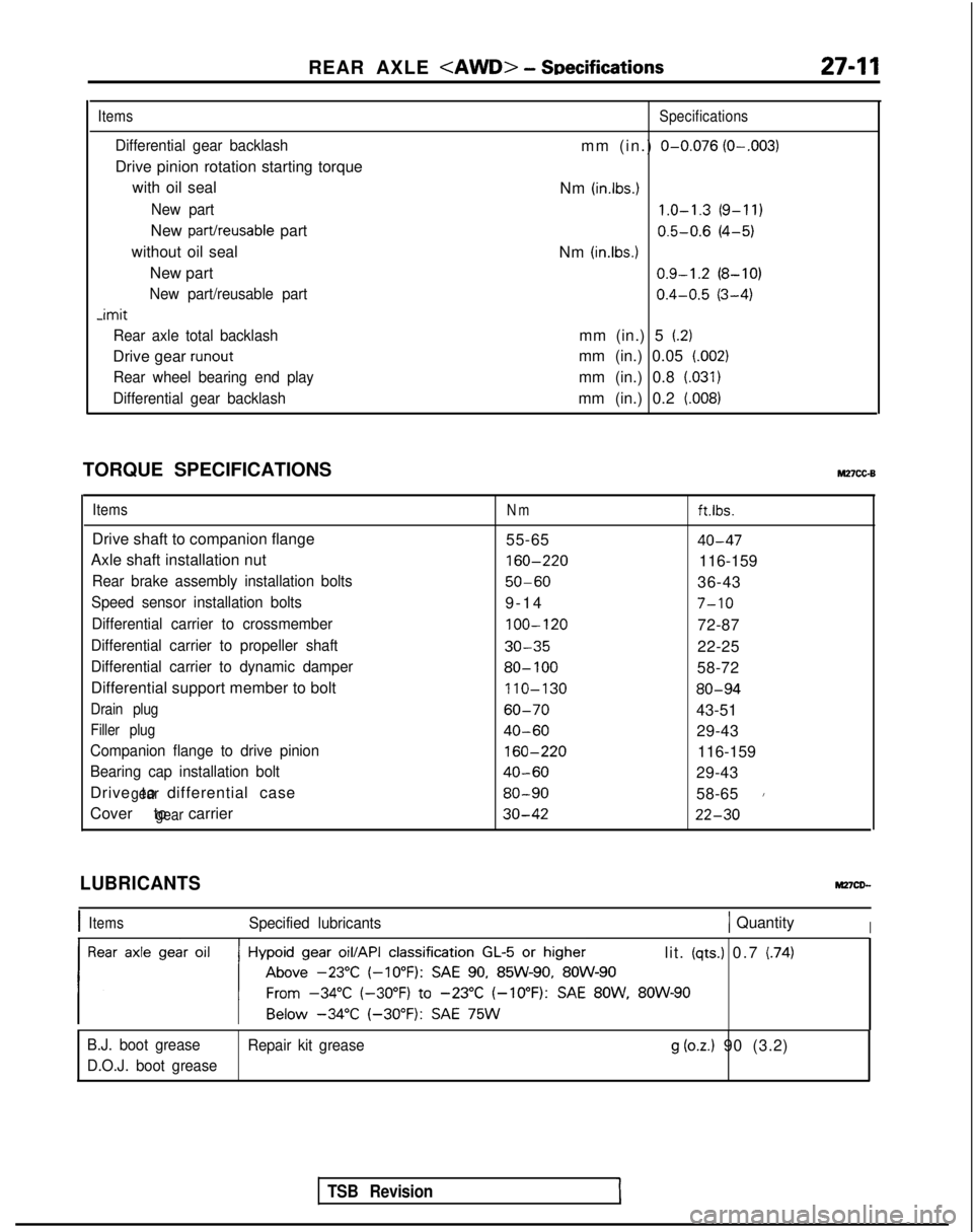
REAR AXLE - SDecifications27-11
Items
Differential gear backlash
Drive pinion rotation starting torque
with oil seal
New part
New part/reusable part
without oil seal New part
New part/reusable part -imit
Rear axle total backlash
Drive gear runout
Rear wheel bearing end play
Differential gear backlash
Specifications
mm (in.) O-0.076 (O-.003)
Nm (in.lbs.) 1.0-1.3
(9-11)
0.5-0.6
(4-5)
Nm
(in.lbs.1 0.9-1.2
(8-10)
0.4-0.5
(3-4)
mm (in.) 5
(2)
mm (in.) 0.05 (.002)
mm (in.) 0.8 (.031)
mm (in.) 0.2 (008)
TORQUE SPECIFICATIONSM27cc-B
ItemsNmft.lbs.
Drive shaft to companion flange 55-6540-47
Axle shaft installation nut 160-220
116-159
Rear brake assembly installation bolts50-6036-43
Speed sensor installation bolts9-1
4
7-10
Differential carrier to crossmember
100-120
72-87
Differential carrier to propeller shaft30-3522-25
Differential carrier to dynamic damper80- 10058-72
Differential support member to bolt 110-130
80-94
Drain plug60-7043-51
Filler plug40-6029-43
Companion flange to drive pinion
160-220
116-159
Bearing cap installation bolt40-6029-43
Drive to differential case
gear80-9058-651
Cover to carriergear30-4222-30
TSB Revision
LUBRICANTS
IItemsSpecified lubricants1 QuantityI
lit. (qts.) 0.7 (74)
B.J. boot grease Repair kit grease
g (oz.) 90 (3.2)
D.O.J. boot grease