1989 MITSUBISHI GALANT brake sensor
[x] Cancel search: brake sensorPage 478 of 1273
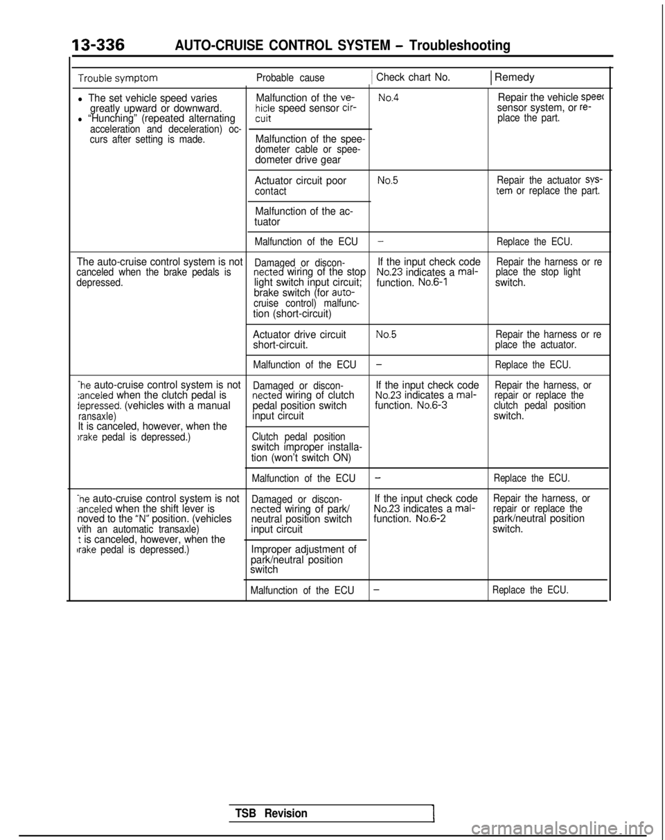
13-336AUTO-CRUISE CONTROL SYSTEM - Troubleshooting
Probable cause1 Check chart No.1 Remedy
l The set vehicle speed variesMalfunction of the ve-No.4Repair the vehicle speec
greatly upward or downward.hicle speed sensor cir-sensor system, or re-l “Hunching” (repeated alternatingcuit place the part.
acceleration and deceleration) oc-
curs after setting is made.
Malfunction of the spee-dometer cable or spee-dometer drive gear
Actuator circuit poor
contact
Malfunction of the ac-
tuator
No.5Repair the actuator sys-tern or replace the part.
Malfunction of the ECU
-Replace the ECU.
The auto-cruise control system is notDamaged or discon-If the input check codeRepair the harness or re
canceled when the brake pedals isnetted wiring of the stopNo.23 indicates a mal- place the stop light
depressed.light switch input circuit; function. No.6-1switch.
brake switch (for auto-
cruise control) malfunc-
tion (short-circuit)
Actuator drive circuit
No.5Repair the harness or reshort-circuit.place the actuator.
Malfunction of the ECU
-Replace the ECU.
-he auto-cruise control system is notDamaged or discon-If the input check codeRepair the harness, or:anceled when the clutch pedal isnetted wiring of clutchNo.23 indicates a mal- repair or replace thedepressed. (vehicles with a manual pedal position switchfunction. No.6-3
clutch pedal position
ransaxle)input circuit switch.
It is canceled, however, when the
)rake pedal is depressed.) Clutch pedal positionswitch improper installa-
tion (won’t switch ON)
Malfunction of the ECU-Replace the ECU.
-he auto-cruise control system is notDamaged or discon-If the input check codeRepair the harness, orzanceled when the shift lever isnetted wiring of park/No.23 indicates a mal- repair or replace thenoved to the “N” position. (vehicles
neutral position switch function. No.6-2park/neutral positionvith an automatic transaxle)input circuit switch.t is canceled, however, when theIrake pedal is depressed.)Improper adjustment of
park/neutral position
switch
Malfunction of the ECU-Replace the ECU.
TSB Revision
Page 493 of 1273
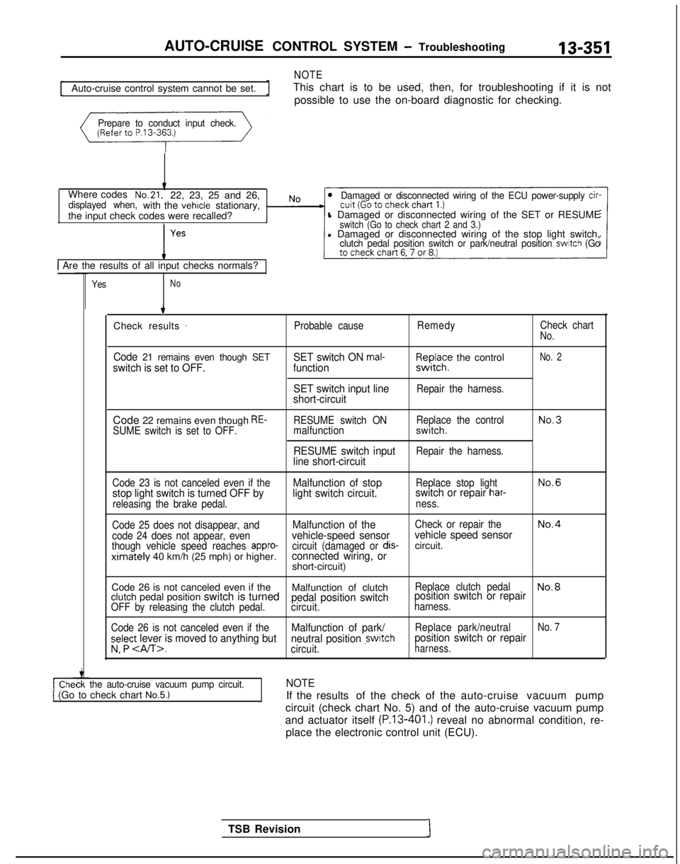
AUTO-CRUISE CONTROL SYSTEM - Troubleshooting
NOTE
13-351
Auto-cruise control system cannot be set.
This chart is to be used, then, for troubleshooting if it is not
possible to use the on-board diagnostic for checking.
Prepare to conduct input check.
Where codesNo.21,22, 23, 25 and 26,displayed when,with the vehicle stationary,
the input check codes were recalled?Damaged or disconnected wiring of the ECU power-supply cir-
l Damaged or disconnected wiring of the SET or RESUMEswitch (Go to check chart 2 and 3.)l Damaged or disconnected wiring of the stop light switch,clutch pedal position switch or park/neutral position switch (Go
1 Are the results of all input checks normals?
YesNo
ck the auto-cruise vacuum pump circuit.1 (Go to check chart No.5.)
TSB Revision1 7
Check results
’Probable cause RemedyCheck chartNo.
Code 21 remains even though SETswitch is set to OFF. SET switch ON mal-function
SET switch input line
short-circuitF,I~JI;? the control
Repair the harness.
No. 2
Code 22 remains even though RE-SUME switch is set to OFF. RESUME switch ON
Replace the controlNo.3malfunctionswitch.
RESUME switch inputRepair the harness.line short-circuit
Code 23 is not canceled even if theMalfunction of stopReplace stop lightNo.6
stop light switch is turned OFF by light switch circuit.switch or repair har-
releasing the brake pedal.
ness.
Code 25 does not disappear, and
Malfunction of theCheck or repair theNo.4
code 24 does not appear, evenvehicle-speed sensor vehicle speed sensorthough vehicle speed reaches appro-circuit (damaged or dis-circuit.ximately 40 km/h (25 mph) or higher.connected wiring, orshort-circuit)
Code 26 is not canceled even if the Malfunction of clutch
Replace clutch pedalNo.8clutch pedal position switch is turnedpedal position switchposition switch or repairOFF by releasing the clutch pedal.
circuit.harness.
Code 26 is not canceled even if the
Malfunction of park/Replace park/neutralNo. 7
select lever is moved to anything but neutral position ,switchposition switch or repair
v. P .circuit.harness.
NOTE
If the results of the check of the auto-cruise vacuum pump
circuit (check chart No. 5) and of the auto-cruise vacuum pump
and actuator itself
(P.13-401.) reveal no abnormal condition, re-
place the electronic control unit (ECU).
Page 494 of 1273
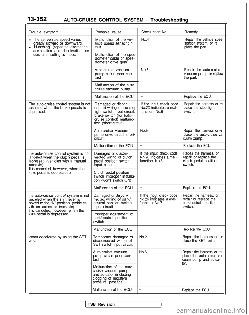
13-352AUTO-CRUISE CONTROL SYSTEM - Troubleshooting
Trouble symptomProbable causeCheck chart No.
Remedy
l The set vehicle speed varies Malfunction of the ve-No.4Repair the vehicle speegreatly upward or downward.hicle speed sensor cir-l “Hunching” (repeated alternatingsensor system, or re-witplace the part.
acceleration and deceleration) oc- curs after setting is made.
Malfunction of the spee-
dometer cable or spee-
dometer drive gear
Auto-cruise vacuum
No.5Repair the auto-cruisepump circuit poor con-vacuum pump or replactactthe part.
Malfunction of the auto-cruise vacuum pump Malfunction of the ECU
-Replace the ECU.
The auto-cruise control system is not Damaged or discon-If the input check code Repair the harness or rezanceled when the brake pedals is netted wiring of the stopNo.23 indicates a mal-
depressed.light switch input circuit; function. No.6place the stop light
switch.
brake switch (for auto-cruise control) malfunc-
tion (short-circuit)
Auto-cruise vacuum
No.5Repair the harness or repump drive circuit short- place the auto-cruise va
circuit.cuum pump.
Malfunction of the ECU
-Replace the ECU.
The auto-cruise control system is not Damaged or discon-If the input check code
Repair the harness, or:anceled when the clutch pedal is netted wiring of clutchNo.26 indicates a mal-repair or replace thedepressed. (vehicles with a manual
pedal position switchfunction. No.8clutch pedal position
ransaxle)input circuitswitch.
It is canceled, however, when theIrake pedal is depressed.) Clutch pedal position
switch improper installa-
tion (won’t switch ON)
Malfunction of the ECU
-Replace the ECU.
*he auto-cruise control system is not Damaged or discon-If the input check code
Repair the harness, or:anceled when the shift lever is netted
wiring of park/No.26 indicates a mal-repair or replace the
noved to the “N” position. (vehicles neutral position switchfunction. No.7park/neutral position
vith an automatic transaxle)input circuit switch.t is canceled, however, when thebrake pedal is depressed.)
Improper adjustment of
park/neutral position
switch
Malfunction of the ECU-Replace the ECU.
anc$ decelerate by using the SET Temporary damaged orNo.2Repair the harness or re-disconnected wiring of
SET switch input circuitplace the SET switch.
Auto-cruise vacuumNo.5Repair the harness or re-pump circuit poor con-
tactplace the auto-cruise va-
cuum pump and actua-
tor.Malfunction of the auto-cruise vacuum pump
and actuator (including
clogging of negative
pressure passage)
Malfunction of the ECU-Replace the ECU.
TSB RevisionI
Page 506 of 1273
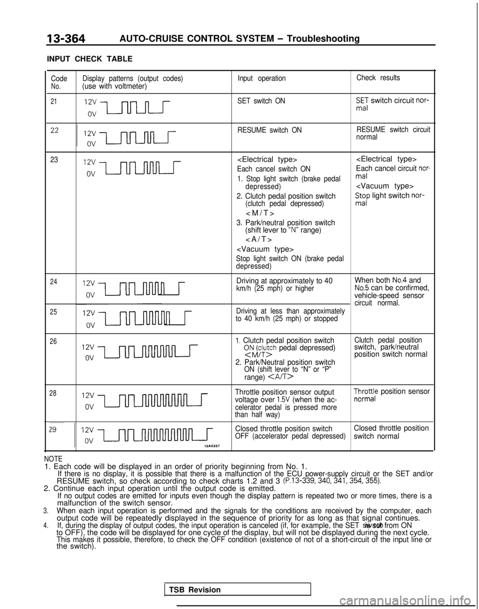
13-364AUTO-CRUISE CONTROL SYSTEM - Troubleshooting
INPUT CHECK TABLE
Code Display patterns (output codes) Input operationCheck resultsNo.(use with voltmeter)
21SET switch ONSmE,: switch circuit nor-
RESUME switch ON RESUME switch circuit
normal
23
Each cancel switch ONEach cancel circuit nor-
1. Stop light switch (brake pedalmal
depressed)
2. Clutch pedal position switch(clutch pedal depressed)
St;p light switch nor-
3. Park/neutral position switch
(shift lever to “N” range)
>
Stop light switch ON (brake pedal
depressed)
24
25
n r
Driving at approximately to 40 When both No.4 and
km/h (25 mph) or higherNo.5 can be confirmed,
vehicle-speed sensor
circuit normal.
n r
Driving at less than approximately
to 40 km/h (25 mph) or stopped
26I. Clutch pedal position switchsNJFy;h pedal depressed)
2. Park/Neutral position switch
ON (shift lever to “N” or “P”
range)
Clutch pedal positionswitch, park/neutral position switch normal
28Throttle position sensor output
voltage over 1.5V (when the ac-celerator pedal is pressed more
than half way)
$yro;e position sensor
Closed throttle position switch Closed throttle position
OFF (accelerator pedal depressed)switch normal
NOTE1. Each code will be displayed in an order of priority beginning from No\
. 1.If there is no display, it is possible that there is a malfunction of th\
e ECU power-supply circuit or the SET and/orRESUME switch, so check according to check charts 1.2 and 3 (P.13-339,340,341,354,355).2. Continue each input operation until the output code is emitted.If no output codes are emitted for inputs even though the display patter\
n is repeated two or more times, there is amalfunction of the switch sensor.3.When each input operation is performed and the signals for the condition\
s are received by the computer, eachoutput code will be repeatedly displayed in the sequence of priority for\
as long as that signal continues.4.If, during the display of output codes, the input operation is canceled \
(if, for example, the SET switch is set from ONto OFF), the code will be displayed for one cycle of the display, but w\
ill not be displayed during the next cycle.This makes it possible, therefore, to check the OFF condition (existenc\
e of not of a short-circuit of the input line orthe switch).
TSB Revision
Page 547 of 1273

AUTO-CRUISE CONTROL SYSTEM - Sewice Adjustment Procedures
ECU connector terminals
19171513ll><7531
2018161412 101 98642
16A1060
ELECTRONIC CONTROL UNIT (ECU) SIGNAL CIRCUIT
CHECK
Disconnect the connector of the ECU, and then check at the
body side wiring harness according to the chart below.
IG SW: Ignition switch
MAIN SW: Main switch
OD SMI: Overdrive switch
Termi-~ Connection or mea-
nal
~
sured part Measure-
Tester con-
ment item nection
Check conditions
Standard
I-
I-
1 ~
Actuator (motor) Resistance1 - “‘2Actuator selector Approx. 120
(Fully closed position)
1
2
3I Stop light switchVoltage3-Ground ~
IG S/W ON, Main SW O
N
Battery positive
~
(for auto-cruise ~
control cancellation)
j )
i (Don’t press brake pedal.)j voltage
and actuator (clutch)I Press brake pedal after checkingBattery positive
5 1 Power supply (MAIN)
/ above.voltage -0V
Voltage5-Ground
1 IG S/W
ON, Main S/W ONBattery positive
voltage
6None-i -i-
7 1
Power supply (IGz)Voltag
e
7-GroundIG SfW O
N
Battery positive
voltage
8*z ~
On-board diagnostic--i- -
TSB Revision
9Accelerator pedal Voltageg-GroundIG SW O
N
Battery positive
switch
(Accelerator pedal free)voltage
1 Press accelerator pedal after/ Battery positive
II checking above.[voltage -0V
IO I Vehicle speed sensor
Voltage1 O-Ground’ W
ith the ignition key at the ON
’ ~
4 voltage
position, slowly turn the speedom- changes/
ca-
eter cable. ble
rotation
11SET switch
Continuity1 l-Ground ’ SET switch ON (Press) Continuity
SET switch OFF (Release) No continuity
12OD switch
13RESUME switch 1
Voltage
Continuity
12-GroundIG SNV ON OD SW ON position
Battery positive
voltage
OD
SW OFF position ~
OV
13-Ground ~
RESUME switch ON (Turn) Continuity
; RESUME switch OFF (Release)
No continuity
14’2 ~
4 A/T control module( -/- I- !
-
I/15 1 Stop light switch load
~
Voltage15-Ground’ Press the brake pedal.Battery positiveside/voltage
16 j Ground
Continuity1 16-GroundAt all times ~
Continuity
Page 728 of 1273
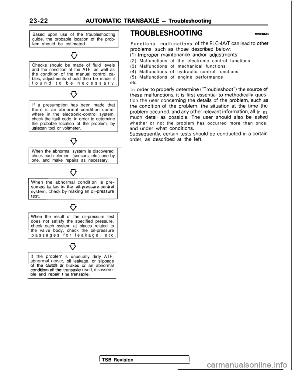
23-22 AUTOMATIC
TRANSAXLE
- Troubleshooting
Based upon use of the troubleshooting
guide, the probable location of the prob-
lem should be estimated.
Checks should be made of fluid levels
and the condition of the ATF, as well as
1 found to be necessary
.
the condition of the manual control ca-
bles; adjustments should then be made if
If a presumption has been made that
there is an abnormal condition some-
where in the electronic-control system,
check the fault code, in order to determine
the probable location of the problem, by using a scan tool or voltmeter.
When the abnormal system is discovered,
check each element (sensors, etc.) one by
one, and make repairs as necessary.
When the abnormal condition is pre- sumed to be in the oil-pressure-control
When the result of the oil-pressure test does not satisfy the specified pressure,
1 passages for leakage, etc
.
check each system at places related to
the valve body, check the oil-pressure
If the problem is unusually dirty ATF,
abnormal noises, oil leakage, or slippage
L##t he traniaxle.1
of the clutch or brakes or an abnormal
condition of the transaxle Itself,
disassem-
TROUBLESHOOTING
Functional malfunctions of the ELGWT can lead to other
problems,
such
as those described
below:
(1) Improper
maintenance
and/or
adjustments
(2) Malfunctions of the electronic control functions
(3) Malfunctions of mechanical functions
(4) Malfunctions of hydraulic control functions
(5) Malfunctions of engine performance
etc.
In order
to properly
determine (“Troubleshoot”)
the
source
of
these
malfunctions,
it is first essential
to methodically ques-
tion
the
user
concerning
the details
of the problem,
such as
the
condition of
the
problem,
the
situation at
the
time the
problem
occurred,
and any other relevant
information, all in as much detail
as possible.
The user
should
also be asked
whether or not the problem has occurred more than once,
and under
what conditions. Subsequently,
certain
tests should
be conducted in a certain
order,
as described
at
the
left.
1 TSB Revision
Page 730 of 1273
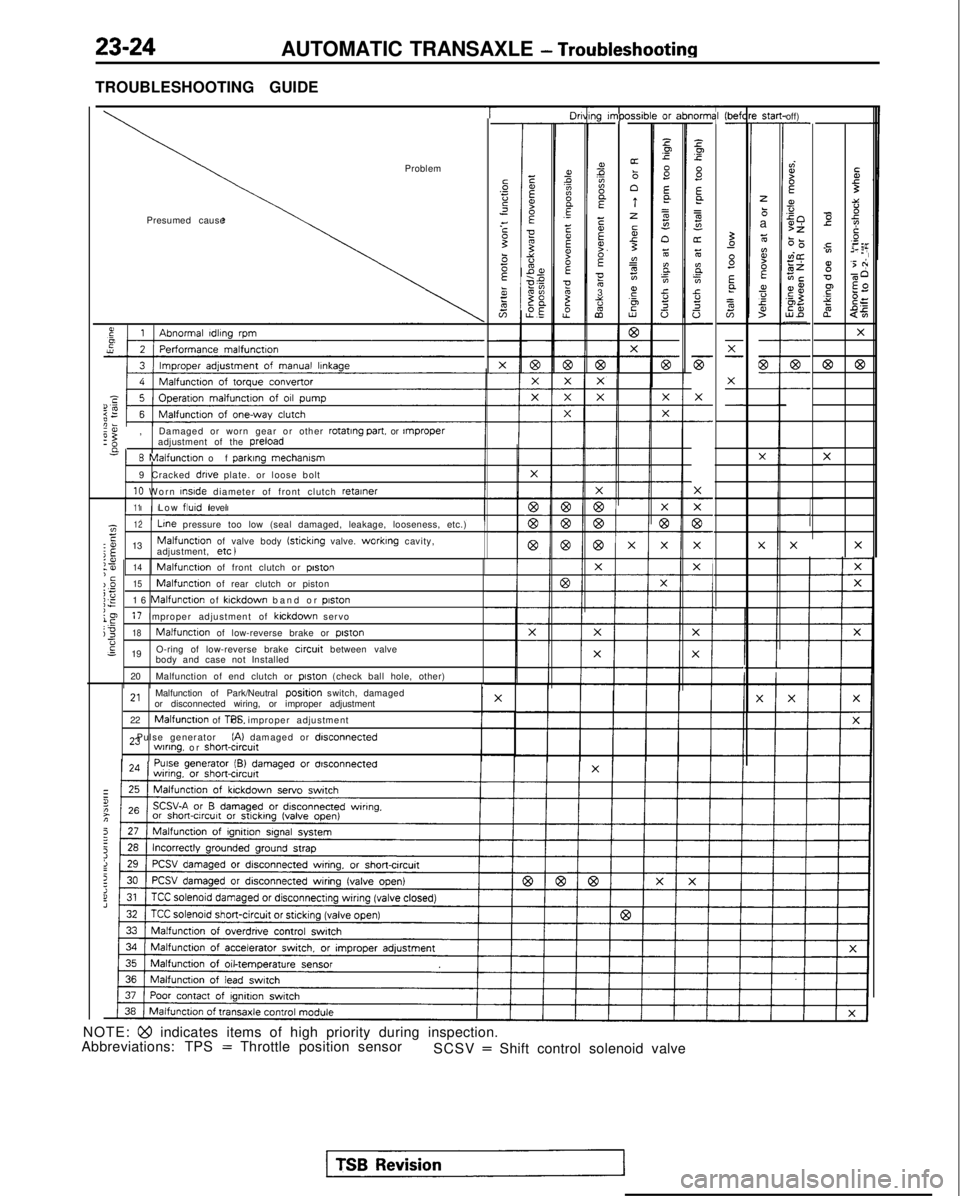
23-24AUTOMATIC TRANSAXLE - Troubleshooting
TROUBLESHOOTING GUIDE
T-----lO"ni31-
z.Ip.c
8Ea
=
s"oz6
E.
;In.ci!
a
-
F
X
-
-
X
77
c-
X
F-
i-
1g I”,PC-
ms?A
E
EEF.E053%
2
xsib-or z-
Pp
s E
a=g
n6
BE0.cY.20 (befl
-St.3-
zbaz
ti?BEa,fs
off)-
dI?f
s50>z6-0vi@zEiECE$,aZ5%-
-
7-
-
Ibr
I
Problem
Presumed causeTi3::-0 e
2Ts
y.=:,02 EF
g'5 +
v-60
F $2
s?
$=
2
$5
X
@63
X
X
I’
-
57-
-X-
-
G-- X
-
-X
X
e:,
Damaged or worn gear or other rotating part.
or rnproperadjustment of the preload
n
8 Malfunction of
parklng
mechamsm
9 Cracked drive plate. or loose bolt
10 Worn InsIde
diameter of front clutch retainer
11Low flutd
level
X
-
1z12 Line
pressure too low (seal damaged, leakage, looseness, etc.)E:o 13Malfunctton of valve body (sticking valve. worktng cavity,
j$adjustment, etc )XX
I
:?I14‘cMalfunction of front clutch or poston
)_O15Malfunction of rear clutch or pistoni;;E16 Malfunction of klckdown band or piston
le17 Improper adjustment of kickdown servoj318Malfunction of low-reverse brake or piston-6s 19 O-ring of low-reverse brake circuit between valve
body and case not Installed
20 Malfunction of end clutch or
piston (check ball hole, other)
2,Malfunction of Park/Neutral positjon switch, damaged
or disconnected wiring, or improper adjustment
22
Malfunction of TPS. or improper adjustment
23 Pulse generator
(A) damaged or disconnectedwlnng. or short&cut^
NOTE: Qo indicates items of high priority during inspection.
Abbreviations: TPS = Throttle position sensor SCSV = Shift control solenoid valve
Page 736 of 1273
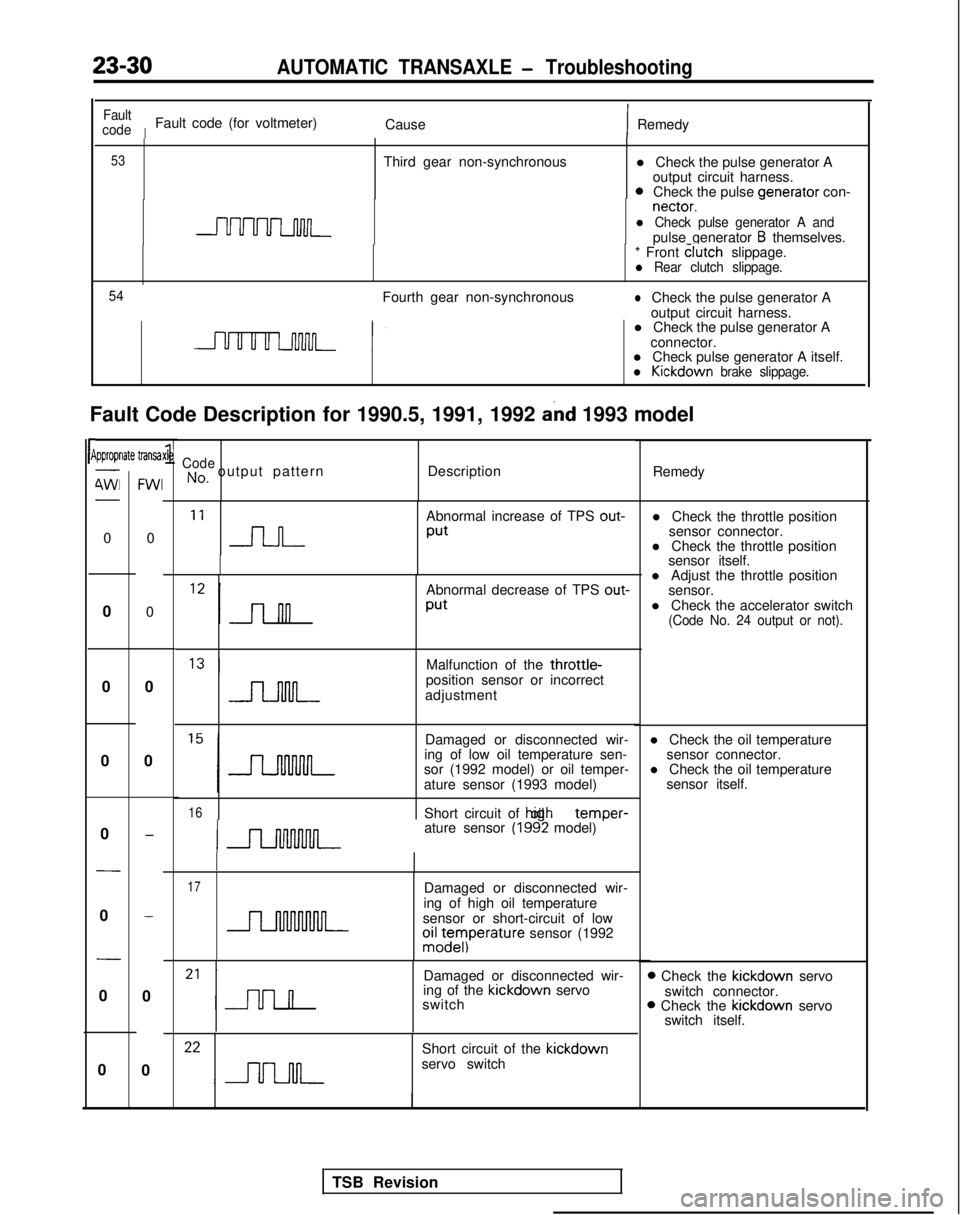
23-30AUTOMATIC TRANSAXLE - Troubleshooting
l Check the pulse generator Aoutput circuit harness.
0Check the pulse venerator
con- nectar.
-l Check pulse generator A andpulse generator B themselves.
Fault Code Description for 1990.5, 1991, 1992
and 1993 model
rP
Fault
code
IFault code (for voltmeter) CauseIRemedy
53Third gear non-synchronous
* Front clutch
slippage.
l Rear clutch slippage.
54
Fourth gear non-synchronouslCheck the pulse generator A
output circuit harness.
l Check the pulse generator A
connector.
l Check pulse generator A itself.
l Kickdown brake slippage.
ipproprlate transa-
4Wl-
0
0
0
0
0
-
0
-
0
0
FWI
0
0
0
0
-
-
0
0
xle1CodeNo, output pattern Description
Remedy
‘I n
Abnormal increase of TPS out-
Put
Abnormal decrease of TPS out-
Put
l Adjust the throttle position
sensor.
l Check the accelerator switch
(Code No. 24 output or not).
Malfunction of the throttle-position sensor or incorrect
adjustment
Damaged or disconnected wir-
ing of low oil temperature sen- l Check the oil temperature
sensor connector.
sor (1992 model) or oil temper- l Check the oil temperature
ature sensor (1993 model) sensor itself.
16Short circuit of hiah oil temDer-
ature sensor (1992 model) ’
17Damaged or disconnected wir-
ing of high oil temperature
sensor or short-circuit of low
oiz;eyIperature sensor (1992
Damaged or disconnected wir-
ing of the kickdown
servo
switch
Short circuit of the kickdown
servo switch l Check the throttle position
sensor connector.
l Check the throttle position sensor itself.
D Check the kickdown
servo
switch connector.
B Check the kickdown
servo
switch itself.
TSB Revision