Page 877 of 1273
REAR AXLE - Axle Shaft27-17
AXLE SHAFT
IEMOVAL
AND INSTALLATION
55-65
Nm 40-47
ftlbs.160-220NmI116-159
Ift.lbs.36-43 50-60ft.lbs. Nm
Post-installation OperationKonnecting of Parking Brake Cable End@Adjusting Parking Brake LeverStroke (Refer to GROUP 36-Service
Adjustment Procedures.)
9-14 Nmq------7-10 ft.lbs.
llA0041
Removal steps
4*1. ifsa.yyed sensor
4*2. Brake caliper assembly3.Brake disc4. Drive shaft mounting nut+I) e+ 5. Self locking nut6.Washer7.Companion flange4*8. Axle shaft assembly+e l +9. Rear rotor l e l + 10.Outer bearing+e ++ 11. Dust cover~~ 12. Dust cover13.Axle shaft4*l 414.Oil seal+e l + 15. inner bearing Trailing
arm 15
SERVICE POINTS OF REMOVAL
MmwAN
1.REMOVAL OF REAR SPEED SENSOR
A.B.S.>
NOTE
Be cautious to ensure that the tip of the pole piece does
not come in contact with other parts
when removing the
speed sensor.
2. REMOVAL OF BRAKE CALIPER ASSEMBLY
Remove the brake caliper assembly and suspend it with a
piece of wire.
I- _,1 TSB RevisionI
Page 944 of 1273

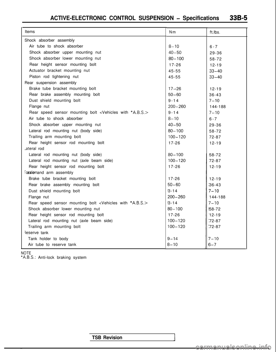
ACTIVE-ELECTRONIC CONTROL SUSPENSION - Specifications33B-5
ItemsNmft.lbs.
Shock absorber assemblyAir tube to shock absorber
Shock absorber upper mounting nut
Shock absorber lower mounting nut
Rear height sensor mounting bolt
Actuator bracket mounting nut
Piston rod tightening nut
Rear suspension assembly Brake tube bracket mounting bolt
Rear brake assembly mounting bolt
Dust shield mounting bolt
Flange nut
8-106-
7
40-5029-36
80-10058-72
17-26 12-19
45-55
33-40
45-5533-40
Rear speed sensor mounting bolt
Air tube to shock absorber
Shock absorber upper mounting nut
Lateral rod mounting nut (body side)
Trailing arm mounting bolt
Rear height sensor rod mounting bolt -ateral
rod 17~26
12-19
50-6036-43
9-1
4
7-10
200-260144-188
9-1
4
7-10
8-106-
7
40-5029-36
80-10058-72
100-12072-87
17-26 12-19
Lateral rod mounting nut (body side)
Lateral rod mounting nut (axle beam side)
Rear height sensor rod mounting bolt rorsion axle and arm assembly
Brake tube bracket mounting bolt
Rear brake assembly mounting bolt
Dust shield mounting bolt
Flange nut
80-100
100-120
17-26 58-72
72-87
12-19
Rear speed sensor mounting bolt
*A.B.S.>
Shock absorber lower mounting nut Rear height sensor rod mounting bolt
Lateral rod mounting nut (axle beam side)
Trailing arm mounting bolt
deserve tank 17-26
50-60
3-14
200-260
3-14
30- 100
17-26
100-120
100-120
12-19
36-43
7-10
144-188
7-10
58-72
12-19
72-87
72-87
Tank holder to body
Air tube to reserve tank
7-10
s-7
TSB Revision
NOTE “A.B.S.:
Anti-lock braking system
Page 958 of 1273

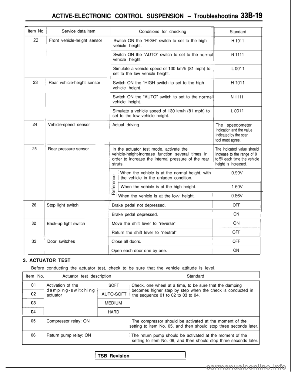
ACTIVE-ELECTRONIC CONTROL SUSPENSION - Troubleshootina 33B-19
rItem No. IService data itemConditions for checking
Switch ON the “HIGH” switch to set to the high
vehicle height.Standard
H 1011
Switch ON the “AUTO” switch to set to the norma
vehicle height.N 1111
Simulate a vehicle speed of 130 km/h (81 mph) to
set to the low vehicle height.ILO011
-cSwitch ON the “HIGH switch to set to the high
vehicle height.HI011
Switch ON the “AUTO” switch to set to the norma
vehicle height.
N 1111
Simulate a vehicle speed of 130 km/h (81 mph) to
set to the low vehicle height.LOO11
Actual driving The speedometer
indication and the value
indicated by the scan
tool must agree.
In the actuator test mode, activate theThe indicated value should
vehicle-height-increase function several times inIncrease to the range of 0
order to increase the internal pressure of the rearto 5V each time the vehicle
struts.height is increased.-
8
i When the vehicle is at the normal height, with
iE Ithe vehicle in the unladen condition. 0.9ov
Front vehicle-height sensor
23
’/Rear vehicle-height sensor
-4
c
24Vehicle-speed sensor
t25Rear pressure sensor
Fa,%When the vehicle is at the high height.
[r i When the vehicle is at the low height.
1.6OV
I0.86VT
26Stop light switch Brake pedal not depressed.IOFFI
Brake pedal depressed.IONIc
32Back-up light switch
33
TDoor switches
I
Move the shift lever to “reverse”
-E-----l
-
Return the shift lever to “neutral”
Close all doors.
IOFF/
Open each door one by one.ION
3. ACTUATOR TEST Before conducting the actuator test, check to be sure that the vehicle a\
ttitude is level.
Item No. Actuator test description Standard
01~
!l
Activation of theSOFT
damping-switching i
I Check, one wheel at a time, to be sure that the damping
02 actuator
t’ becomes higher step by step when the check is conducted in
AUTO-SOFT ~the sequence 01 to 02 to 03 to 04.
03MEDIUM
04 HARD
05
Compressor relay: ON The compressor should be activated at the moment of the
setting to item No. 05, and then should stop three seconds later.
Return pump relay: ON ~
The return pump should be activated at the moment of the
setting to item No. 06, and then should stop three seconds later.
06
1 TSB Revision
Page 1025 of 1273

33B-86 ACTIVE-ELECTRONIC CONTROL SUSPENSION - ~~u,:~%i?:~~~~
REAR UNDER FLOOR
G-05 ACTIVE-ECS rear vehicle-height sensor
16A0266
SERVICE ADJUSTMENT PROCEDURAZ
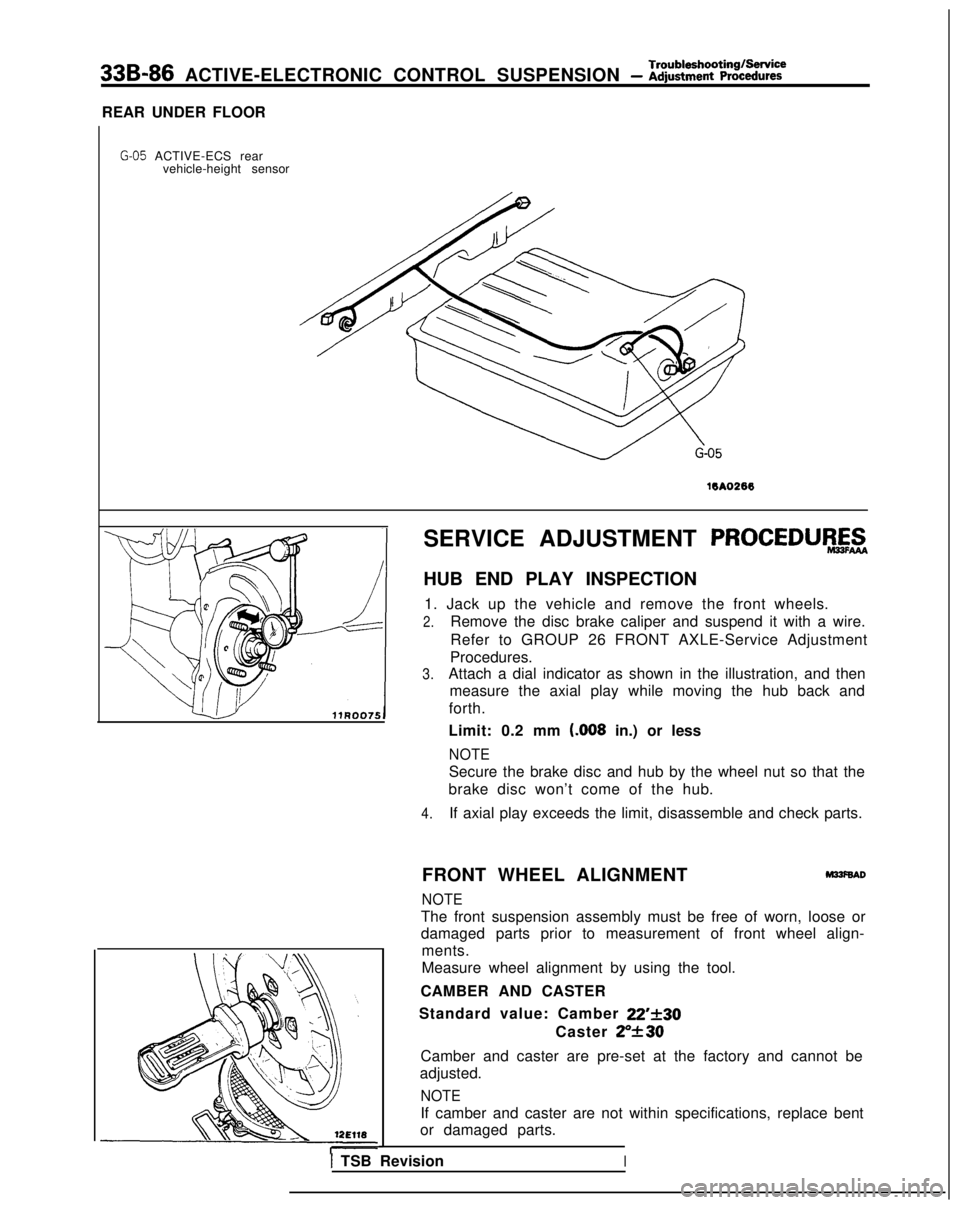
HUB END PLAY INSPECTION
1. Jack up the vehicle and remove the front wheels.
2.Remove the disc brake caliper and suspend it with a wire.
Refer to GROUP 26 FRONT AXLE-Service Adjustment
Procedures.
3.Attach a dial indicator as shown in the illustration, and then measure the axial play while moving the hub back and
forth.
Limit: 0.2 mm t.008
in.) or less
NOTE
Secure the brake disc and hub by the wheel nut so that the
brake disc won’t come of the hub.
4.If axial play exceeds the limit, disassemble and check parts.
FRONT WHEEL ALIGNMENT
M33f6AD
NOTE
The front suspension assembly must be free of worn, loose or
damaged parts prior to measurement of front wheel align- ments.
Measure wheel alignment by using the tool.
CAMBER AND CASTER
Standard value: Camber
22’f30
Caster ZY30
Camber and caster are pre-set at the factory and cannot be
adjusted.
NOTE
If camber and caster are not within specifications, replace bent
or damaged parts.
I TSB RevisionI
Page 1036 of 1273
ACTIVE-ELECTRONIC CONTROL SUSPENSION - Strut Assembly33B-97
STRUT ASSEMBLYM33zOAC
REMOVAL AND INSTALLATION
6
40-50 Nm
29-36 ft.lbs.
Right side
17-26 Nm 12-19
ftlbs.
12A0230
Removal steps
1. Dust cover
l + 2. Air tube
3. O-ring
4.Bush5.Actuator connector
6. Front strut upper mounting nut
7.Actuator
4*8. Front height sensor rod::9.Brake hose and tube clamp
10. Front speed sensor clamp
4*11. Front strut lower mounting bolts12. Front strut upper mounting nuts
+a 13. Strut assembly
16-76
ft.lbs.
TSB Revision1
Page 1037 of 1273

33B-98ACTIVE-ELECTRONIC CONTROL SUSPENSION - Strut Assembly i
SERVICE POINTS OF REMOVALM33lBAE
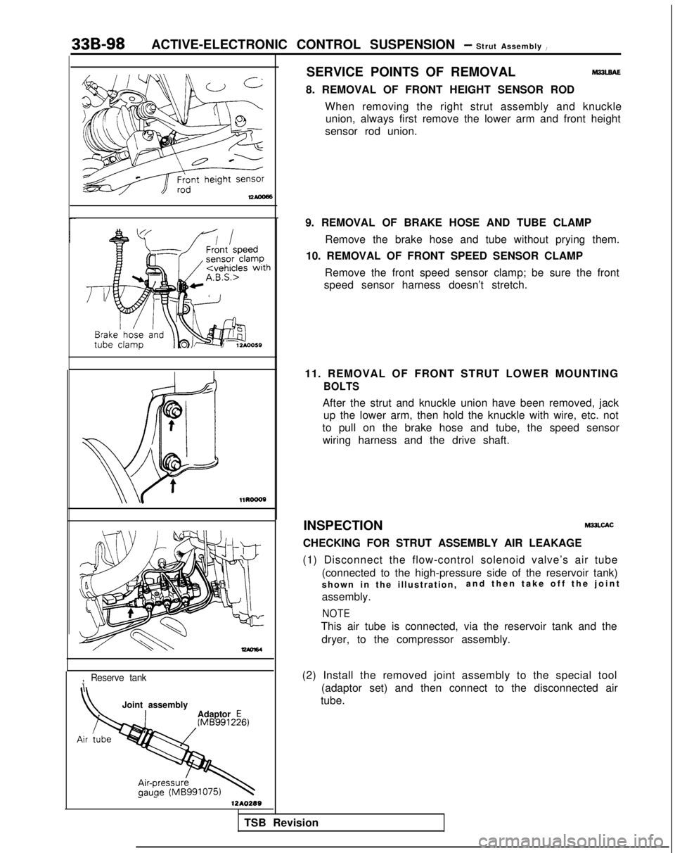
8. REMOVAL OF FRONT HEIGHT SENSOR RODWhen removing the right strut assembly and knuckleunion, always first remove the lower arm and front height
sensor rod union. l1RoooP
-
,Reserve tank
Joint assembly
Adaptor E
1 -1210289
9. REMOVAL OF BRAKE HOSE AND TUBE CLAMP
Remove the brake hose and tube without prying them.
10. REMOVAL OF FRONT SPEED SENSOR CLAMP
Remove the front speed sensor clamp; be sure the front
speed sensor harness doesn’t stretch.
11. REMOVAL OF FRONT STRUT LOWER MOUNTING
BOLTS
After the strut and knuckle union have been removed, jack up the lower arm, then hold the knuckle with wire, etc. not
to pull on the brake hose and tube, the speed sensor wiring harness and the drive shaft.
INSPECTION
M33LCAC
CHECKING FOR STRUT ASSEMBLY AIR LEAKAGE
(1) Disconnect the flow-control solenoid valve’s air tube (connected to the high-pressure side of the reservoir tank)
shown in the illustration, and then take off the join
t
assembly.
NOTE
This air tube is connected, via the reservoir tank and the dryer, to the compressor assembly.
(2) Install the removed joint assembly to the special tool (adaptor set) and then connect to the disconnected air
tube.
TSB Revision
Page 1053 of 1273
33B-114 ACTIVE-ELECTRONIC CONTROL SUSPENSION - ~:h%pension
REAR SUSPENSION ASSEMBLYM33GA-A
REMOVAL AND INSTALLATION
50-60 Nm
17-26 Nm 36-43 ftlbs.
12-19
ft.lbs. 2
,
9-14
‘Nm7-10 ftlbs.
Vehicles with A.B.S. 9-14 Nm
7-10 ft.lbs.
12A0366
Removal steps1. Parking brake cable
2. Brake tube and hose bracket
3. Rear disc brake
4. Brake disc
5. Hub cap
l + 6. Flange nut
7. Washer
8. Speed sensor
9. Rear axle assembly
10. Dust shield 200-260
Nm
12A0355
%I*Removal of Trunk Room Srde Tnm
Post-installation Operationl installation of Trunk Room SideTrim. (Refer to GROUP 52-Trims.)l Check the Brake Disc Runout, andAdjust.(Refer to GROUP
35-ServiceAdjustment. Procedures.)l Check the Rear Disc Brakes Drag-ging Torque, and Adjust.(Refer to GROUP
35-ServiceAdjustment Procedures.)achecking Parking Brake LeverStroke.(Refer to GROUP
36-ServiceAdjustment Procedures.)@Check the Rolling Diaphragm forDouble-folding.(Refer to P.33B-89.)
TSB Revision
Page 1058 of 1273
Torsion Axle andACTIVE-ELECTRONIC CONTROL SUSPENSION - Arm Assemblv33B-119
TORSION AXLE AND ARM ASSEMBLYMSPA-A
F
{EMOVAL
AND INSTALLATION
17-26 Nm
._. _.T-10 ftlbs.
12AO355
Vehicles with A.B.S.
9-14 Nm
7-10 ftlbs.
I
12AO356
1
Removal steps
1. Parking brake cable
2. Brake hose and tube bracket
3. Rear disc brake
4. Rear brake disc
5. Hub capea 6. Flange nut
7. Washer
8. Speed sensor
9. Rear axle assembl
y
IO. Dust shield
1 TSB Revision
Post-installation Operationl Check the Brake Disc Runout, and
Adiust.I(Refer to GROUP 35-ServiceAdjustment Procedures.)
NIheck
the Rear Disc Brakes Drag-
ging Torque, and Adjust.(Refer to GROUP 35-ServiceAdjustment Procedures.)l Checking for Parking Brake Lever
Stroke.
(Refer to GROUP 35-ServiceAdjustment Procedures.)