1988 PONTIAC FIERO automatic transmission
[x] Cancel search: automatic transmissionPage 1069 of 1825
700-R4.18 AUTOMATIC TRANSMISSION
Case Assembly
a Clean
o Thoroughly with solvent
a Air dry
- do not wipe with cloth
Lo and Reverse Clutch Assembly
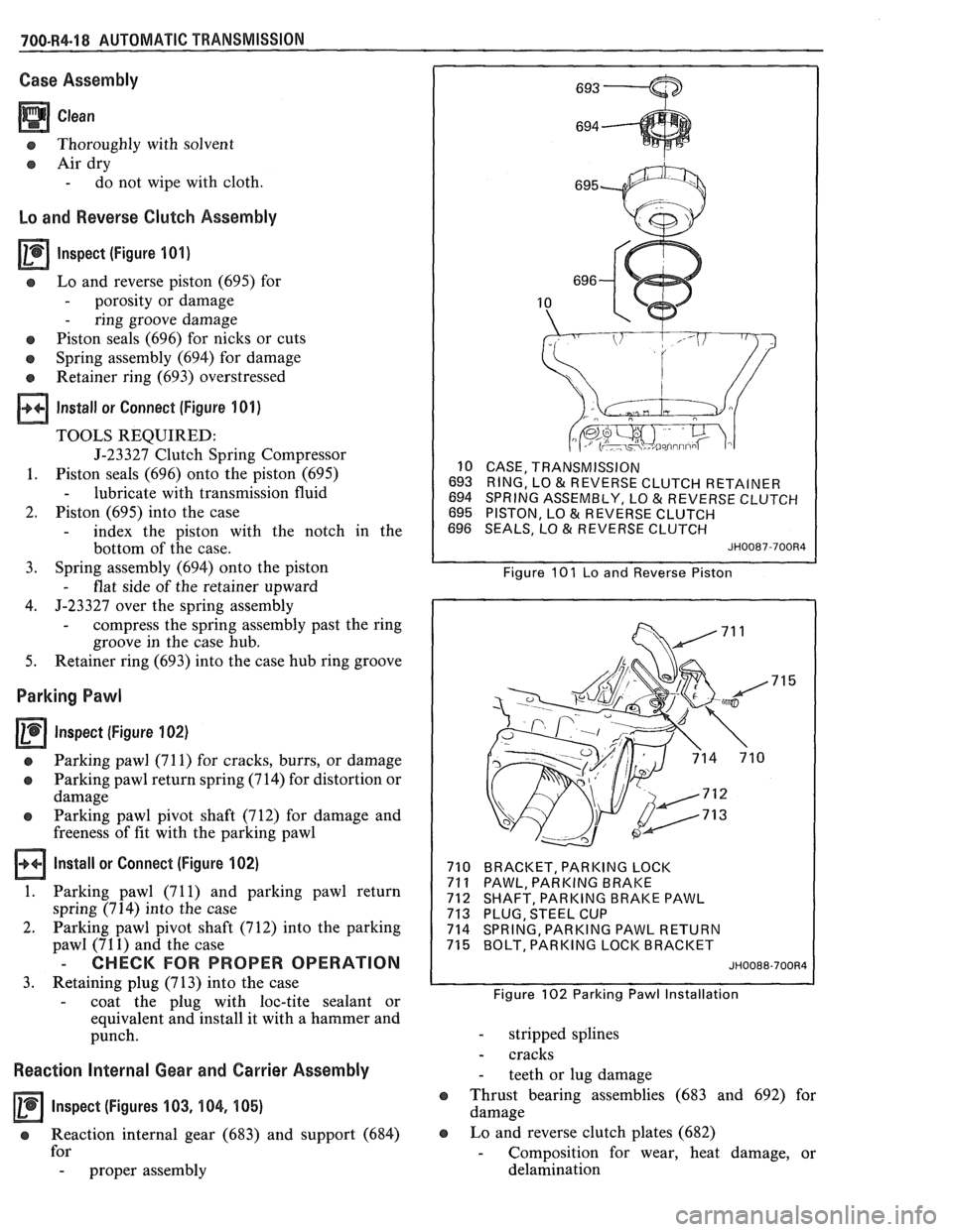
lnspect (Figure 101)
s Lo and reverse piston (695) for
- porosity or damage
- ring groove damage
e Piston seals (696) for nicks or cuts
o Spring assembly (694) for damage
Retainer ring (693) overstressed
Install or Connect (Figure 101)
TOOLS REQUIRED:
J-23327 Clutch Spring Compressor
1. Piston seals (696) onto the piston (695)
- lubricate with transmission fluid
2. Piston (695) into the case
- index the piston with the notch in the
bottom of the case.
3. Spring
assembly (694) onto the piston
- flat side of the retainer upward
4. J-23327 over
the spring assembly
- compress the spring assembly past the ring
groove in the case hub.
5. Retainer ring (693) into the case hub ring groove
Parking Pawl
Inspect (Figure 102)
a Parking pawl (71 1) for cracks, burrs, or damage
o Parking pawl return spring (714) for distortion or
damage
e Parking pawl pivot shaft (712) for damage and
freeness of fit with the parking pawl
Install or Connect (Figure 102)
1. Parking pawl (71 1) and parking pawl return
spring (714) into the case
2. Parking pawl pivot shaft (712) into the parking
pawl (71
1) and the case
- CHECK FOR PROPER OPERATION
3. Retaining plug (713) into the case
- coat the plug with loc-tite sealant or
equivalent and install it with a hammer and
punch.
Reaction Internal Gear and Carrier Assembly
Inspect (Figures 103, 104, 105)
e Reaction internal gear (683) and support (684)
for
- proper assembly
10 CASE, TRANSMISSION
693 RING, LO
& REVERSE CLUTCH RETAINER
694 SPRING ASSEMBLY, LO & REVERSE CLUTCH
695 PISTON, LO & REVERSE CLUTCH
696 SEALS, LO & REVERSE CLUTCH
JH0087-700R4
Figure 101 Lo and Reverse Piston
710 BRACKET, PARKING LOCK
71
1 PAWL, PARKING BRAKE
712 SHAFT, PARKING BRAKE PAWL
713 PLUG, STEEL CUP
714 SPRING, PARKING PAWL RETURN
715 BOLT, PARKING LOCK BRACKET
JH0088-700R4
Figure 102 Parking Pawl Installation
- stripped splines
- cracks
- teeth or lug damage
e Thrust bearing assemblies (683 and 692) for
damage
e Lo and reverse clutch plates (682)
- Composition for wear, heat damage, or
delamination
Page 1070 of 1825
AUTOMATIC TRANSMISSION 700-R4-19
- Steel for heat damage or surface finish
damage
Reaction carrier assembly (681) for
- pinion gear damage
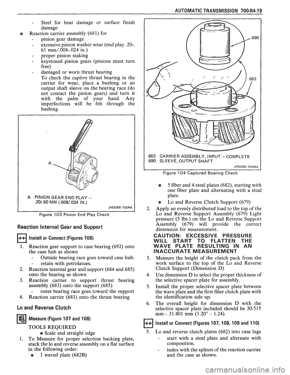
- excessive pinion washer wear (end play -20-.
61 mm/.008-.024 in.)
- proper pinion staking
- keystoned pinion gears (pinions must turn
free)
- damaged or worn thrust bearing
To check the captive thrust bearing in the
carrier for wear, place a bushing or an
output shaft sleeve on the bearing race (do
not contact the pinion gears) and turn it
with the palm of your hand. Any
imperfections will be felt through the
bushing.
A PINION GEAR END PLAY -
.20/.60 MM (.008/.024 IN .)
Figure 103 Pinion End Play Check
Reaction Internal Gear and Support
lnstall or Connect (Figures 106)
1. Reaction gear support to case bearing (692) onto
the case hub as shown
- Outside bearing race goes toward case hub.
- retain with petrolatum.
2. Reaction internal gear and support (684 and 685)
onto the bearing as shown
3. Reaction carrier to support thrust bearing
assembly (683) onto the support (685)
- outer bearing race goes toward the support
4. Reaction carrier (681) onto the thrust bearing
Lo and Reverse Clutch
Measure (Figure 107 and 108)
TOOLS REQUIRED
e Scale and straight edge
1. To Measure for proper selection backing plate,
stack the lo and reverse assembly on a flat surface
in the following order:
o 1 waved plate (682B)
662
CARRIER ASSEMBLY, I NPU'T - COMPLETE
690 SLEEVE, OUTPUT SHAFT
JH0090-700R4
Figure 104 Captured Bearing Check
5 fiber and 4 steal plates (682), starting with
one fiber plate and alternating with a steal
plate.
Lo and Reverse Clutch Support (679)
2. Apply an evenly distributed load to the top of the
Lo and Reverse Support Assembly (679) Light
pressure (5 lbs.) on the Lo and Reverse Support
Assembly (679) will provide the correct
dimension for measurement.
CAUTION: EXCESSIVE PRESSURE
WILL START TO FLATTEN THE
WAVE PLATE RESULTING IN AN
INACCURATE MEASUREMENT
3. Measure
the height of the clutch pack from the
work surface to the top of the Lo and Reverse
Clutch Support (Dimension D)
4. Use dimension D to select the proper thickness of
the selective spacer plate for assembly.
5. Install the proper selective spacer plate between
the wave plate and the first fiber clutch plate with
the identification side up.
6. The
overall height for dimension D with the
selective spacer plate included should be 30.515
mm
- 31.401 mm (1.20" - 1.24).
Install or Connect (Figures 107, 108, 109 and 110)
5. Lo and reverse clutch plates (682) into case lugs
- start with a steel plate and alternate with
composition.
- index with the splines of the reaction carrier
and the case as shown.
Page 1071 of 1825
700-R4-20 AUTOMATIC f RANSMlSSlON
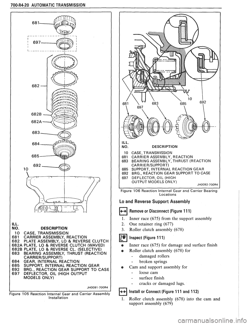
ILL. NO. DESCRIPTION
10 CASE, TRANSMISSION
681 CARRIER ASSEMBLY, REACTION
682 PLATE ASSEMBLY, LO
& REVERSE CLUTCH
682A PLATE, LO
& REVERSE CLUTCH (WAVED) 6828 PLATE, LO & REVERSE CL. (SELECTIVE)
683 BEARING ASSEMBLY, 'THRUST (REACTION
CARRIERISUPPORT) 684 GEAR, INTERNAL REACTION
685 SUPPORT, INTERNAL REACTION GEAR
692 BRG., REACTION GEAR SUPPORT TO CASE
697 DEFLECTOR, OIL (HIGH OUTPUT
MODELS ONLY)
Figure
105 Reaction Internal Gear and Carrier Assembly Installation
ILL.
NO. DESCRIPTION
10 CASE, TRANSMISSION
681 CARRlER ASSEMBLY, REACTION 683 BEARING ASSEMBLY, THRUST (REACTION
CARR I
ER/SUPPORT) 685 SUPPORT, INTERNAL REACTION GEAR 692 BRG., REACTION GEAR SUPPORT TO CASE
697 DEFLECTOR, OIL (HIGH
1 OUTPUT MODELS ONLY) JH0092-700Rd I 1 I Figure 106 Reaction lnternal Gear and Carrier Bearing
Locations
Lo and Reverse Support Assembly
Remove or Disconnect (Figure 11 1)
1. Inner race (675) from the support assembly
2. One retainer ring (677)
3. Roller clutch assembly (678)
@ inspect (figure I 11)
e Inner race (675) for damage and surface finish
a Roller clutch assembly (678) for
- damaged rollers
- broken springs
a Cam and support assembly for
- loose cam
- surface finish
- cracks or damaged lugs.
Install or Connect (Figure 11 1 and 112)
1. Roller clutch assembly (678) into the cam and
support assembly (679)
Page 1072 of 1825
AUTOMATIC TRANSMISSION 700.R4-21
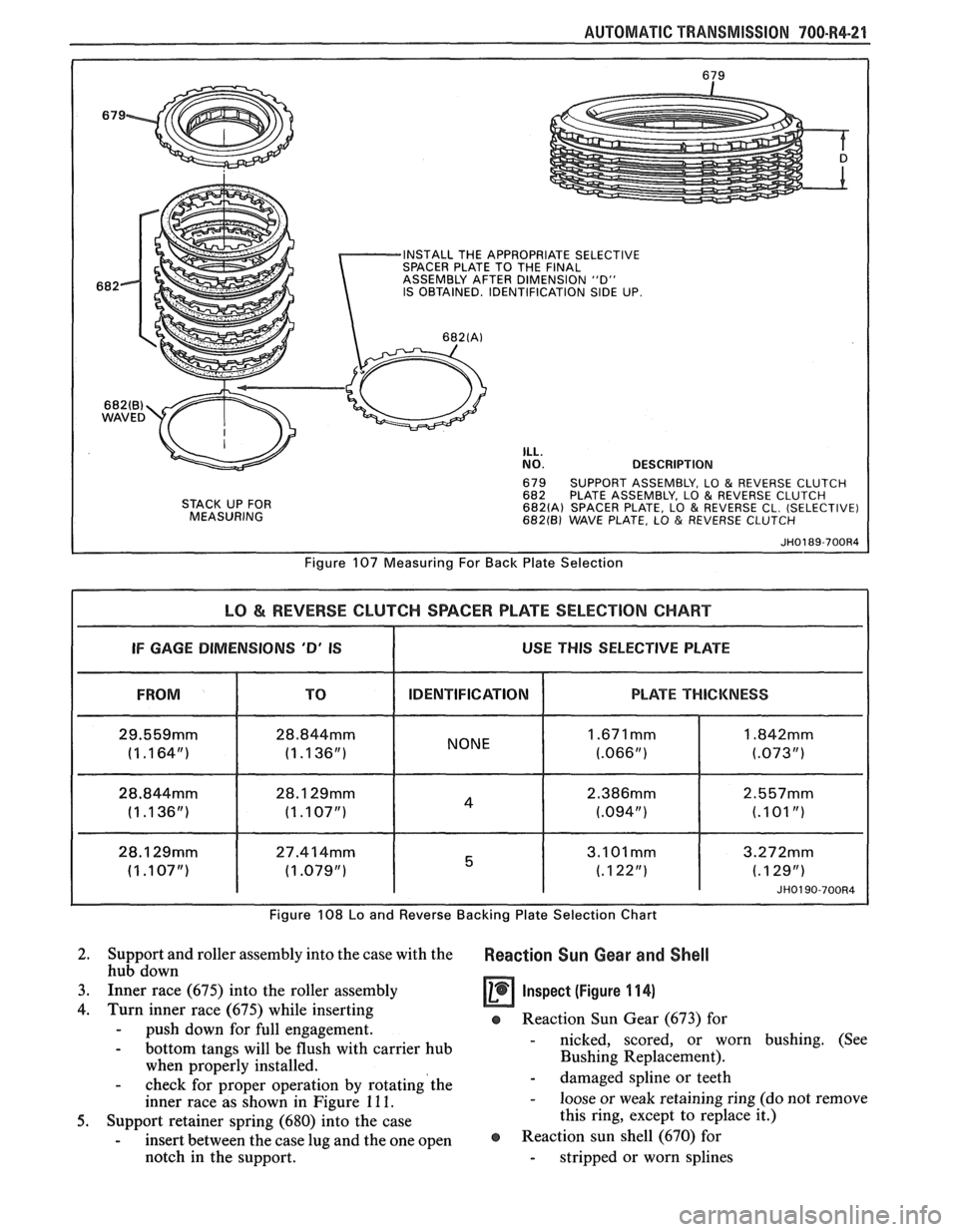
INSTALL THE APPROPRIATE SELECTIVE
SPACER PLATE TO THE FINAL
ASSEMBLY AFTER DIMENSION "D"
IS OBTAINED. IDENTIFICATION
SIDE UP.
682(B) WAVED
STACK UP FOR
MEASURING
ILL. NO. DESCRIPTION
679 SUPPORT ASSEMBLY, LO & REVERSE CLUTCH
682 PLATE ASSEMBLY, LO & REVERSE CLUTCH 682(A) SPACER PLATE, LO & REVERSE CL. (SELECTIVE) 682(B) WAVE PLATE, LO & REVERSE CLUTCH
Figure 107 Measuring For Back Plate Selection
LO & REVERSE CLUTCH SPACER PLATE SELECTION CHART
I IF GAGE DIMENSIONS 'D' IS I USE THIS SELECTIVE PLATE I
FROM IDENTIFICATION
28.844mm
(1 .I 36") I NONE
Figure 108 Lo and
Reverse Backing Plat
PLATE THICKNESS
JH0190-700R4
? Selection Chart
2. Support and roller assembly into the case with the Reaction Sun Gear and Shell hub down
3. Inner race (675) into the roller assembly
Inspect (Figure 11 4)
4. Turn inner race (675) while inserting e Reaction Sun Gear (673) for - push down for full engagement.
- bottom tangs will be flush with carrier hub - nicked, scored, or worn bushing. (See
when properly installed. Bushing Replacement).
- check for
proper operation by rotating'the - damaged spline or teeth
inner race as shown in Figure
11 1. - loose or weak retaining ring (do not remove
5. Support retainer spring (680) into the case this
ring, except to replace it.)
- insert between the case lug and the one open @ Reaction sun shell (670) for
notch in the support. - stripped or worn splines
Page 1073 of 1825
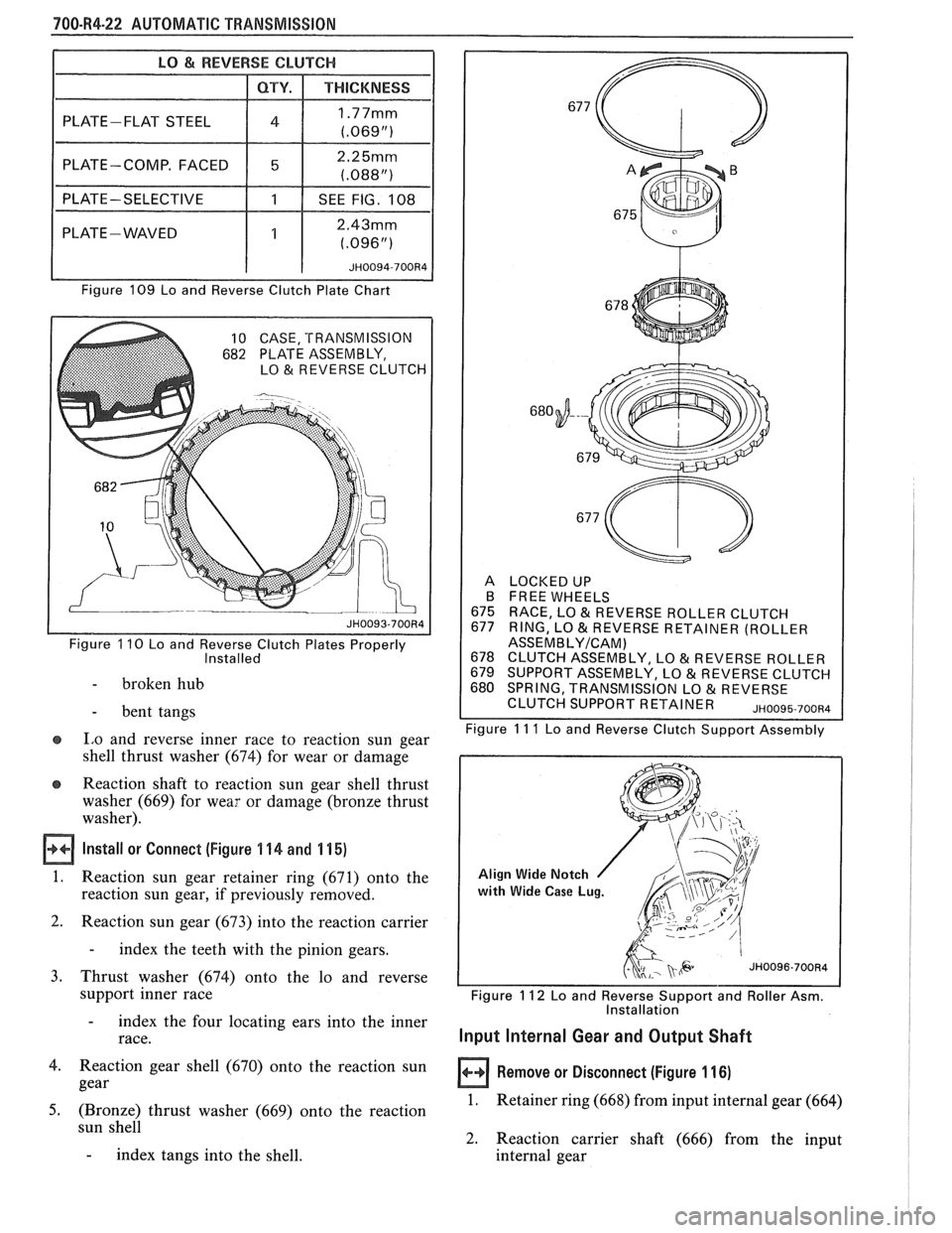
700-R4-22 AUTOMATIC TRANSMISSION
I PLATE-COMP. FACED 2.25mm
1 1 (.088") I
I PLATE-SELECTIVE I 1 I SEE FIG. 108 1
PLATE - WAVED 2.43mm
Figure 109 Lo and Reverse Clutch Plate Chart
10 CASE, TRANSMISSION
682 PLATE ASSEMBLY,
LO&REVERSECLUTCH
Figure 110 Lo and Reverse Clutch Plates Properly Installed
- broken hub
- bent tangs
e I,o and reverse inner race to reaction sun gear
shell thrust washer (674) for wear or damage
e Reaction shaft to reaction sun gear shell thrust
washer (669) for wear or damage (bronze thrust
washer).
Install or Connect (Figure 4 44 and 1 15)
1. Reaction sun gear retainer ring (671) onto the
reaction sun gear, if previously removed.
2. Reaction sun gear (673) into the reaction carrier
- index the teeth with the pinion gears.
3. Thrust washer (674) onto the lo and reverse
support inner race
- index the four locating ears into the inner
race.
4. Reaction gear shell (670) onto the reaction sun
gear
5. (Bronze) thrust washer (669) onto the reaction . , sun shell
- index tangs into the shell.
A LOCKEDUP
B FREE WHEELS
675 RACE, LO
& REVERSE ROLLER CLUTCH
677 RING, LO & REVERSE RETAINER (ROLLER ASSEMBLYICAM) 678 CLUTCH ASSEMBLY, LO & REVERSE ROLLER
679 SUPPORT ASSEMBLY, LO 81 REVERSE CLUTCH
680 SPRING, TRANSMISSION LO & REVERSE
CLUTCH SUPPORT R ETA1 NE R ~~oog5.700~4 - -- Figure I I I Lo and Reverse Clutch Support Assembly
Align Wide Notch
with
Wide Case Lug.
I I Figure 1 12 Lo and Reverse Support and Roller Asm.
Installation
Input Internal Gear and Output Shaft
Remove or Disconnect (Figure 11 6)
1. Retainer ring (668) from input internal gear (664)
2. Reaction carrier shaft (666) from the input
internal gear
Page 1074 of 1825
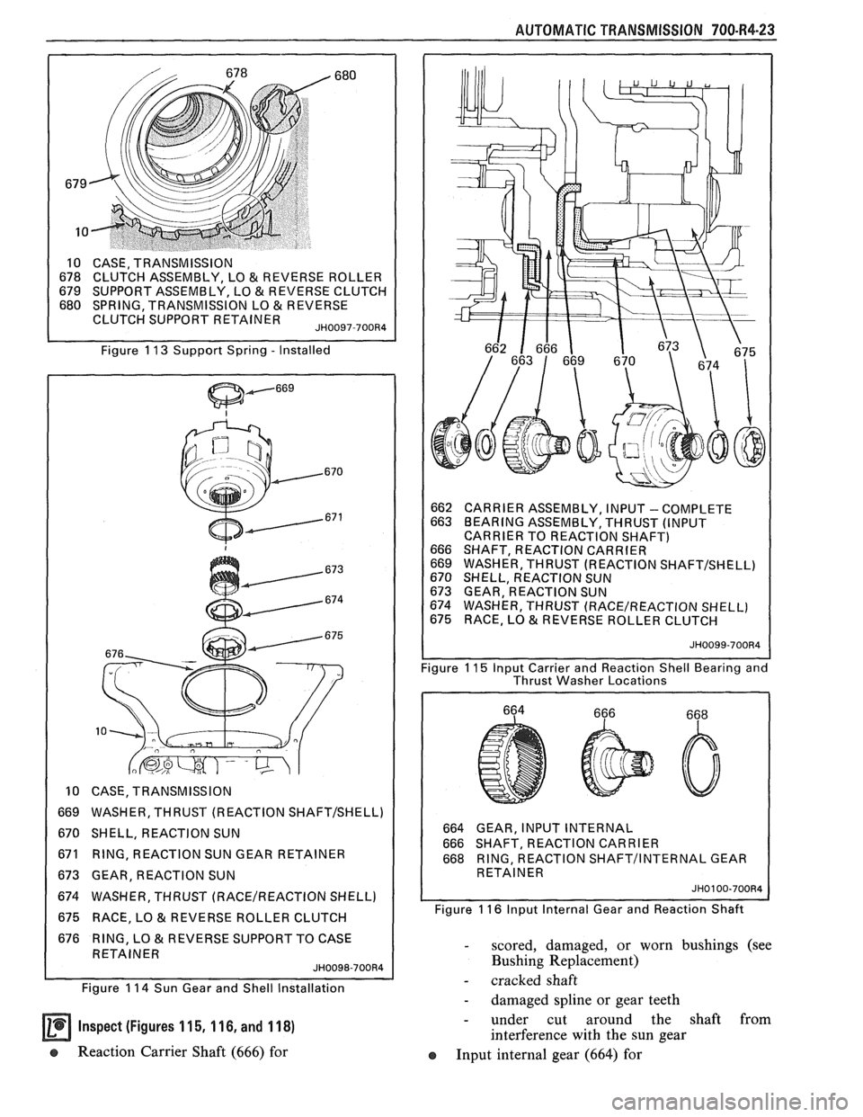
AUTOMATIC TRANSMISSION 700-R4-23
Y, LO & REVERSE ROLLER
662 CARRIER ASSEMBLY, INPUT
- COMPLETE
663 BEARING ASSEMBLY, THRUST (INPUT
CARRIER TO REACTION SHAFT)
666 SHAFT, REACTION CARRIER
669 WASHER, THRUST (REACTION
SHAFTISHELL) 670 SHELL, REACTION SUN
673 GEAR, REACTION SUN
674 WASHER, THRUST
(RACE/REACTION SHELL)
675 RACE, LO
& REVERSE ROLLER CLUTCH
Thrust Washer Locations
10 CASE, TRANSMISSION
669 WASHER, THRUST (REACTION
SHAFT/SHELL)
670 SHELL, REACTION SUN 664 GEAR, INPUT INTERNAL
666 SHAFT, REACTION CARRIER
671 RING, REACTION SUN GEAR RETAINER 668 RING, REACTION
SHAFTIINTERNAL GEAR
673 GEAR, REACTION SUN RETAINER
674 WASHER, THRUST
(RACEIREACTION SHELL)
675 RACE, LO
& REVERSE ROLLER CLUTCH Figure 11 6
Input Internal Gear and Reaction Shaft
676 RING, LO
& REVERSE SUPPORT TO CASE - scored, damaged, or worn bushings (see
Bushing Replacement)
Figure 1 14 Sun Gear and Shell Installation - cracked shaft
- damaged spline or gear teeth
Inspect (Figures 1 15, 1 16, and 1 18) - under cut around the shaft from
interference with the sun gear
e Reaction Carrier Shaft (666) for
Input internal gear (664) for
Page 1075 of 1825
"1QO-R4-24 AUTOMATIC TRANSMISSION
- cracks
- damaged spline or gear teeth
Input carrier to reaction shaft thrust bearing
(663) for wear or damage
Ouput shaft (687)
- plugged or restrictred lube passages
- damaged splines or ring groove
- damaged governor drive gear teeth
- burrs or damage to the front of the shaft at
seal area. (Polish with crocus cloth if
necessary)
- burrs or damage to bearing journals
- damaged teeth on speed sensor rotor
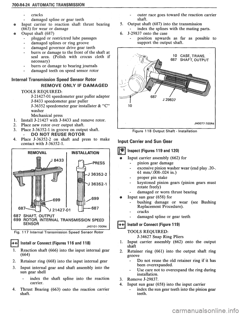
Internal Transmission Speed Sensor Rotor
REMOVE ONLY IF DAMAGED
TOOLS REQUIRED:
J-2 1427-0 1 speedometer gear puller adapter
5-8433 speedometer gear puller
J-36352 speedometer gear installater
& "C"
washer
Mechanical press
1. Install J-21427 with J-8433 and remove rotor.
2. Place new rotor over output shaft.
3. Place J-36352-1 in groove on output shaft.
- DO NOT REUSE ROTOR
4. Place 5-36352-2 on shaft and press to make
contact with
5-36352- 1.
L TRANSMISSION SPEED
Fig. 1 17 Internal f ransmission Speed Sensor Rotor
Install or Connect (Figures 1 16 and 1 18)
1. Reaction shaft (666) into the input internal gear
(664)
2. Retainer ring (668) into the input internal gear
3. Input internal gear and shaft assembly into the
sun gear shell
- index the shaft spline into the reaction
carrier.
4. Thrust Bearing (663) onto the reaction carrier
shaft.
- outer race goes toward the reaction carrier
shaft.
5. Output shaft (687) into the transmission
- index the splines with the mating parts.
6. J-29837 onto the case
- position upwards as far as possible to
support the output shaft.
Figure 1 18 Output Shaft - Installation
Input Carrier and Sun Gear
Inspect (figures 1 19 and 120)
e Input carrier assembly (662) for
- pinion gear damage
- excessive pinion washer wear (end play 20-.
61 mm/.008-.024 in,)
- proper pin stake
- keystoned pinion gears (pinion gears must
rotate freely)
- damaged or worn thrust bearing
e Input sun gear (658) for
- bushing damage or wear (see Bushing
Replacement Procedure).
- cracks
- damaged spline or gear teeth
Install or Connect (Figure 1 19)
TOOLS REQUIRED:
5-34627 Snap Ring Pliers
1. Input carrier assembly (662) onto the output
shaft
2. Retainer ring (661) into the output shaft ring
groove
- Do not reuse the old retainer ring if it has
been overexpanded.
- Use care not to overexpand the ring during
installation.
3. Remove J-29837.
4. Input sun gear (658) into the input carrier
- index the sun gear teeth into the pinion gear
teeth.
Page 1076 of 1825
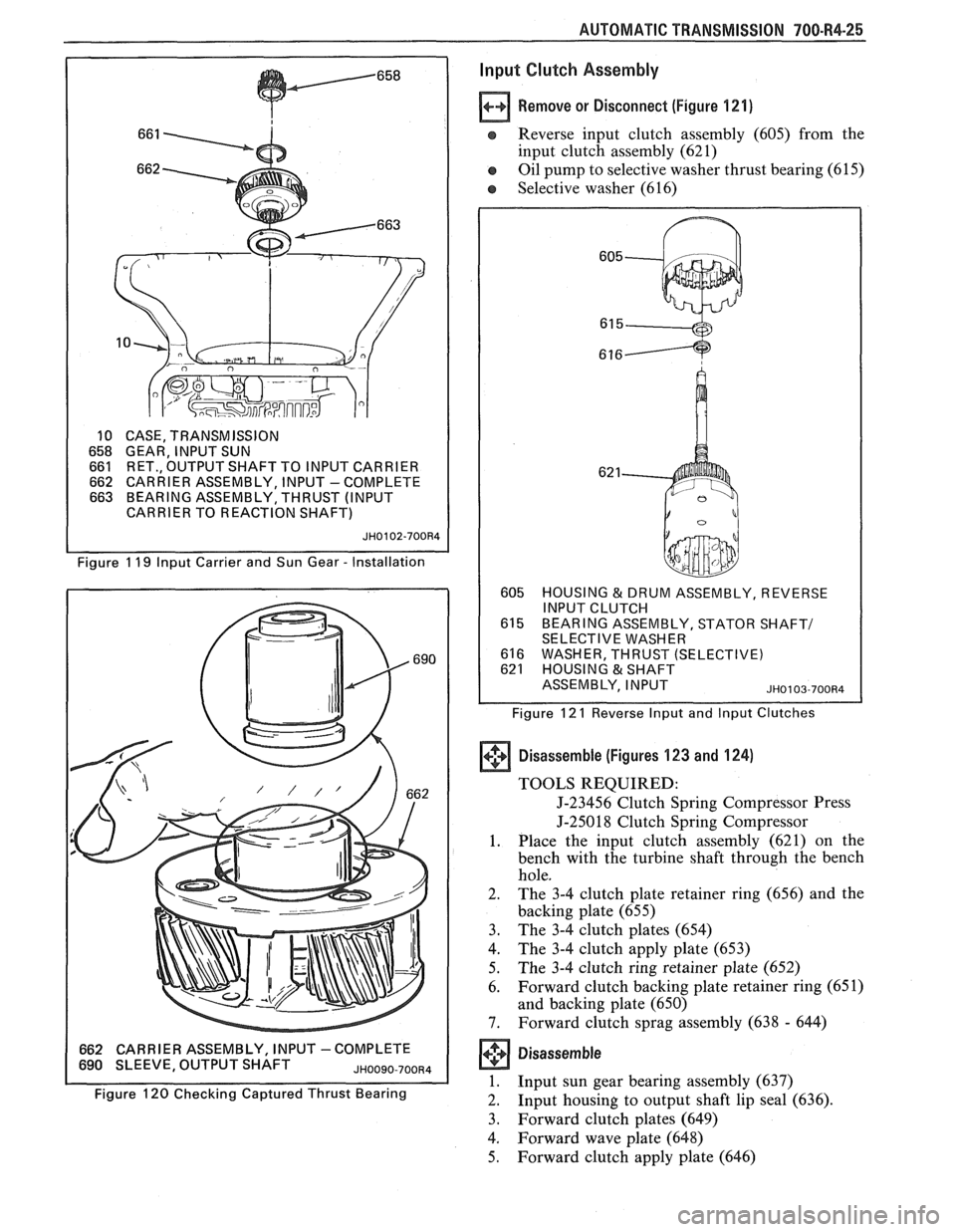
AUTOMATIC TRANSMISSION 700-R4-25
10 CASE, TRANSMISSION
658 GEAR, INPUT SUN 661 RET., OUTPUT SHAFT TO INPUT CARRIER 662 CARRIER ASSEMBLY, INPUT -COMPLETE 663 BEARING ASSEMBLY, THRUST (INPUT
CARRIER TO REACTION SHAFT)
JH0102-700R4
Figure 1 19 lnput Carrier and Sun Gear - Installation
662 CARRIER ASSEMBLY, INPUT -COMPLETE 690 SLEEVE, OUTPUT SHAFT JHOO~O-700~4
Figure 120 Checking Captured Thrust Bearing
lnput Clutch Assembly
Remove or Disconnect (Figure 121)
e Reverse input clutch assembly (605) from the
input clutch assembly (62 1)
e Oil pump to selective washer thrust bearing (61 5)
e Selective washer (616)
605 HOUSING & DRUM ASSEMBLY, REVERSE
INPUT CLUTCH
615 BEARING ASSEMBLY, STATOR SHAFT1 SELECTIVE WASHER
616 WASHER, THRUST (SELECTIVE) 621 HOUSING & SHAFT
ASSEMBLY, INPUT
~~0103-700134
Figure 12 1 Reverse lnput and lnput Clutches
+'+ Disassemble (Figures 123 and 124) (I]
TOOLS REQUIRED:
J-23456 Clutch Spring Compressor Press
J-25018 Clutch Spring Compressor
1. Place the input clutch assembly (621) on the
bench with the turbine shaft through the bench
hole.
2. The 3-4 clutch plate retainer ring (656) and the
backing plate (655)
3. The
3-4 clutch plates (654)
4. The 3-4 clutch apply plate (653)
5. The 3-4 clutch ring retainer plate (652)
6. Forward
clutch backing plate retainer ring (65
1)
and backing plate (650)
7. Forward clutch sprag assembly (638 - 644)
Disassem bie
1. Input sun gear bearing assembly (637)
2. Input
housing to output shaft lip seal (636).
3. Forward clutch plates (649)
4. Forward wave plate (648)
5. Forward clutch apply plate (646)