1988 PONTIAC FIERO automatic transmission
[x] Cancel search: automatic transmissionPage 1085 of 1825
700-R4.34 AUTOMATIC TRANSMISSION
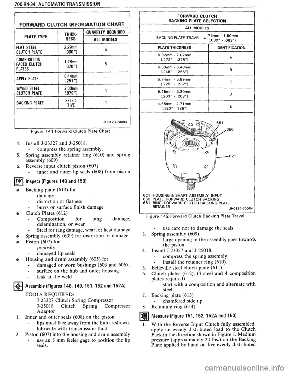
FORWARD CLUTCH INFORMAT ION CHART
THICK.
ALL MODELS
COMPOSITION
FACED CLUTCH
Figure 14 I Forward Clutch Plate Chart
4. Install J-23327 and J-25018.
- compress the spring assembly.
5. Spring assembly retainer ring (610) and spring
assembly (609)
6. Reverse
input clutch piston (607)
- inner and outer lip seals (608) from piston
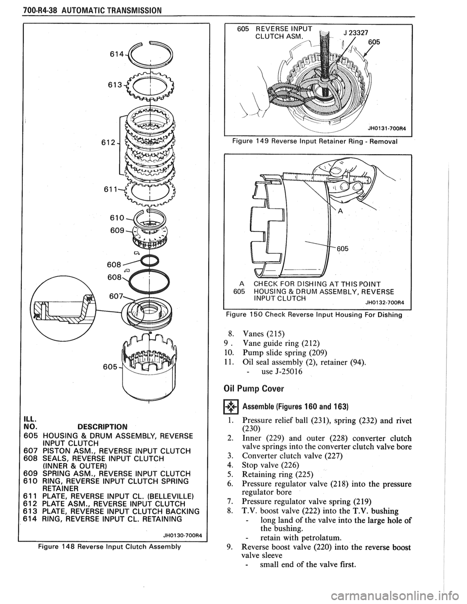
Inspect (Figures 148 and 150)
e Backing plate (613) for
- damage
- distortion or flatness
- burrs or surface finish damage
Clutch Plates (612)
- Composition for tang damage,
delamination, or wear
- Steel for tang damage, wear, or heat damage
o Spring assembly (609) for distortion or damage
o Piston (607) for
- poposity
- damaged lip seals
o Housing and drum assembly (605) for
- damaged or worn bushings (603 and 606)
- surface on the hub and outer housing
- leak at the weld
Assemble (Figures 148, 1 49, 151, 152 and 152A)
TOOLS REQUIRED:
5-23327 Clutch Spring Compressor
J-25018 Clutch Spring Compressor
Adaptor
1. Inner and outer seals (608) on the piston
- lips must face away from the hub as shown.
- lubricate with transmission fluid.
2. Piston (607) into the housing and drum assembly
- use an 8 mm feeler gage to position the lip
seals.
FORWARD CLUTCH BACKING PLATE SELECTION
I ALL MODELS
BACKING PLATE TRAVEL =':,~~,--'~~$~
621 HOUSING & SHAFT ASSEMBLY, INPUT
650 PLATE, FORWARD CLUTCH BACKING
651 RING, FORWARD CLUTCH BACKING PLATE
RETAINER
JH0124-700R4
Figure 142 Forward Clutch Backing Plate Travel
- use care not to damage the seals.
3. Spring assembly (609)
- large opening in the assembly goes towards
the piston.
4. Install J-23327 and
J-25018.
- compress the spring assembly
- install the retainer ring (610).
5. Belleville steel
clutch plate (61 1)
6. Clutch
plates (612).
(4 steel and 4 composition
plates required)
- start with a composition and alternate with
steel
7. Backing plate (613)
- chamfered side up
8. Retaining ring (614)
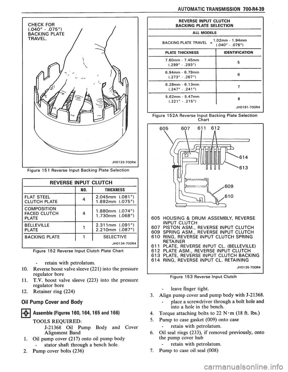
Measure (Figure 151,152,152A and 153)
1. With the Reverse Input Clutch fully assembled,
apply an evenly distributed load to the Clutch
Pack in the direction shown in Figure
1. Medium
pressure (approximately 20 lbs.) on the Backing
Plate applied by hand on five evenly distributed
Page 1086 of 1825
AUTOMATIC TRANSMISSION 700.R4-35
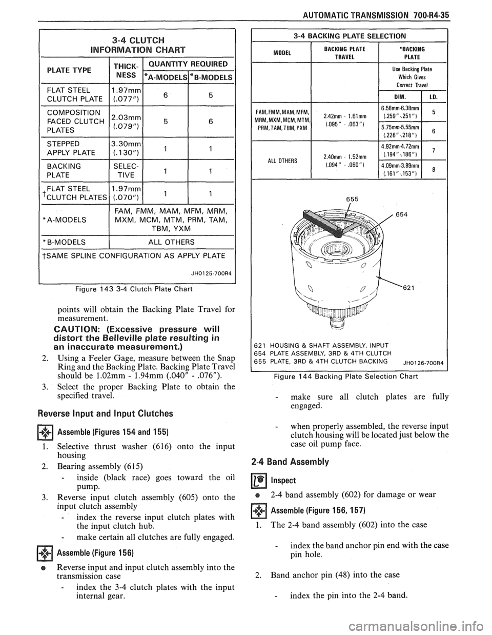
3-4 CLUTCH
INFORMATION CHART
PLATE TYPE THICK- / NESS
FLAT STEEL 11.97mml 6 15 1
CLUTCH
PLATE (.077")
COMPOSITION I 1 1 1
FACED CLUTCH ~:~~~~
PLATES
STEPPED
tSAME SPLINE CONFIGURATION AS APPLY PLATE
" A-MODELS
Figure 143 3-4 Clutch Plate Chart
FAM,
FMM, MAM, MFM, MRM,
MXM, MCM, MTM, PRM, TAM,
TBM, YXM
points will obtain the Backing Plate Travel for
measurement.
CAUTION: (Excessive pressure will
distort the
Belleville plate resulting in
an inaccurate measurement.)
2. Using a Feeler Gage, measure between the Snap
Ring and the Backing Plate. Backing Plate Travel
should be
1.02mm - 1.94mm (.040" - .076").
3. Select the proper Backing Plate to obtain the
specified travel.
Reverse lnput and Input Clutches
Assemble (Figures
154 and 155)
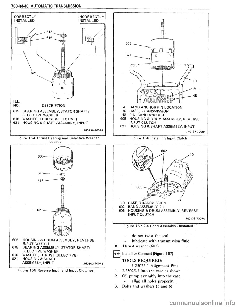
1. Selective thrust washer (616) onto the input
housing
2. Bearing assembly (6 15)
- inside (black race) goes toward the oil
Pump.
3. Reverse input clutch assembly (605) onto the
input clutch assembly
- index the reverse input clutch plates with
the input clutch hub.
- make certain all clutches are fully engaged.
Assemble (Figure 156)
a Reverse input and input clutch assembly into the
transmission case
- index the 3-4 clutch plates with the input
internal gear.
I 3-4 BACKING PLATE SELECTION I
BACKING PLATE
'ODE' I TRAVEL
FAM,FMM,MAM,MFM, 2,42mm . 1,61mm MRM,MXM,MCM,MTM, 1,095,, - .063 ,,, PRM, TAM, TBM, YXM
ALL OTHERS
2.40mm - 1.52mm
1.094" - .060")
621 HOUSING & SHAFT ASSEMBLY, INPUT
654 PLATE ASSEMBLY, 3RD & 4TH CLUTCH
655 PLATE, 3RD & 4TH CLUTCH BACKING ~~0126-700~4
Figure 144 Backing Plate Selection Chart
- make sure all clutch plates are fully
engaged.
- when properly assembled, the reverse input
clutch housing will be located just below the
case oil pump face.
2-4 Band Assembly
a 2-4 band assembly (602) for damage or wear
Assemble (Figure 156, 157)
1. The
2-4 band assembly (602) into the case
- index the band anchor pin end with the case
pin hole.
2. Band
anchor pin (48) into the case
- index the pin into the 2-4 band.
Page 1087 of 1825
700-R4-36 AUTOMATIC TRANSMISSION
619 RING, OIL SEAL (TURBINE 621 HOUSING & SHAFT ASSE
JH0128-700R4
2. OVERRUN CLUTCH 4. 3 -4 CLUTCH
3. FORWARD CLUTCH
Figure
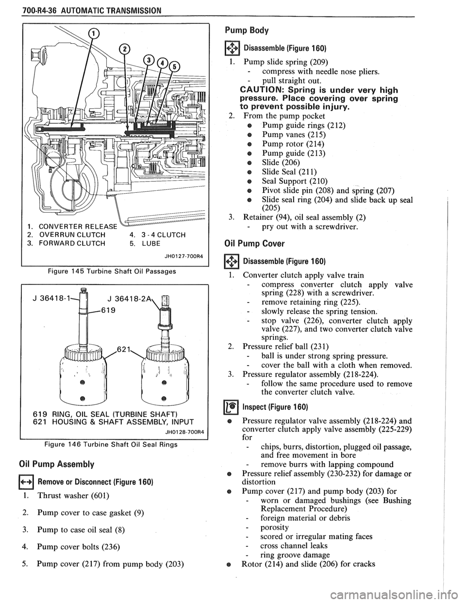
145 Turbine Shaft Oil Passages
Figure
146 Turbine Shaft Oil Seal Rings
Oil Pump Assembly
Remove or Disconnect (Figure 160)
1. Thrust washer (601)
2. Pump cover to case gasket (9)
3. Pump to case oil seal (8)
4. Pump cover bolts (236)
5. Pump cover (217) from pump body (203)
Pump Body
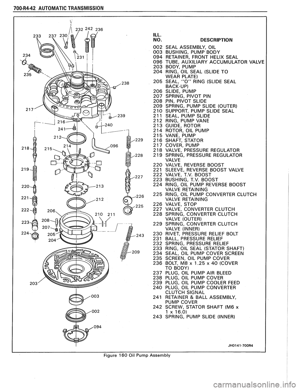
Disassemble (Figure 160)
1. Pump slide spring (209)
- compress with needle nose pliers.
- pull straight out.
CAUTION: Spring is under very high
pressure. Place covering over spring
to prevent possible injury.
2. From the pump pocket
e Pump guide rings (212)
Pump vanes (215)
e Pump rotor (214)
e Pump guide (213)
e Slide (206)
e Slide Seal (21 1)
e Seal Support (210)
e Pivot slide pin (208) and spring (207)
e Slide seal ring (204) and slide back up seal
(205)
3.
Retainer (94), oil seal assembly (2) - pry out with a screwdriver.
Oil Pump Cover
Disassemble (Figure 160)
1.
Converter clutch apply valve train
- compress converter clutch apply valve
spring (228) with a screwdriver.
- remove retaining ring (225). - slowly release the spring tension. - stop valve (226), converter clutch apply
valve
(227), and two converter clutch valve
springs.
2. Pressure relief ball (231)
- ball is under strong spring pressure. - cover the ball with a cloth when removed.
3. Pressure regulator assembly (2 18-224).
- follow the same procedure used to remove
the converter clutch valve.
Inspect (Figure 160)
e Pressure regulator valve assembly (2 18-224) and
converter clutch apply valve assembly (225-229)
for
- chips, burrs, distortion, plugged oil passage,
and free movement in bore
- remove burrs with lapping compound
e Pressure relief assembly (230-232) for damage or
distortion
e Pump cover (217) and pump body (203) for - worn or damaged bushings (see Bushing
Replacement Procedure)
- foreign material or debris
- porosity
- scored or irregular mating faces
- cross channel leaks
- ring groove damage
e Rotor (214) and slide (206) for cracks
Page 1088 of 1825
AUTOMATIC TRANSMISSION 700-R4-37
600 SPRING ASM., BOOST 3-4 CLUTCH 639 HUB, OVERRUN CLUTCH
61 9 RING, OIL SEAL (TURBINE SHAFT) 641 RETAINER & RACE ASSEMBLY, SPRAG
620 RETAINER & CHECK BALL ASSEMBLY 642 FORWARD SPRAG ASSEMBLY
621 HOUSING
& SHAFT ASSEMBLY, INPUT 643 RETAINER RINGS, SPRAG ASSEMBLY
622 SEAL, "0" RING INPUT TO FORWARD HSG. 644 RACE, FORWARD CLUTCH (OUTER)
623 PISTON, 3RD & 4TH CLUTCH 645 PLATE ASSEMBLY, OVERRUN CLUTCH
624 SEAL, 3RD
& 4TH CL. (INNER & OUTER) (STEEL & COMP.)
625 RING, 3RD
& 4TH CLUTCH APPLY 646
PLATE, FORWARD CLUTCH APPLY
626 SPRING ASSEMBLY, 3RD & 4TH CLUTCH 648 PLATE, FORWARD CLUTCH (WAVED)
628 HOUSING, FORWARD CLUTCH 649
PLATE ASSEMBLY, FORWARD CLUTCH
629 SEAL, FORWARD CLUTCH (INNER
& OUTER) 650 PLATE, FORWARD CLUTCH BACKING (SEL.)
630 PISTON, FORWARD CLUTCH 651
RING, FORWARD CLUTCH BACKING PLATE
631 SEAL, OVERRUN CLUTCH (INNER & OUTER) RETAINER
632 PISTON, OVERRUN CLUTCH 652
PLATE, 3RD & 4TH CLUTCH RING RETAINER
634 SPRING ASSEMBLY, OVERRUN CLUTCH 653 PLATE, 3RD & 4TH CL. APPLY (STEPPED)
635 SNAP RING, OVERRUN CLUTCH SPRING 654 PLATE ASSEMBLY, 3RD & 4TH CLUTCH
RETAINER 655 PLATE, 3RD
& 4TH CLUTCH BACKING (SEL.) 636 SEAL, INPUT HOUSING TO OUTPUT SHAFT 656 RING, 3RD & 4TH CLUTCH BACKING
637 BEARING ASSEMBLY, INPUT SUN GEAR PLATE
RETAINER
638 SNAP RING, OVERRUN CL. HUB RETAINING
~~0129-700~4
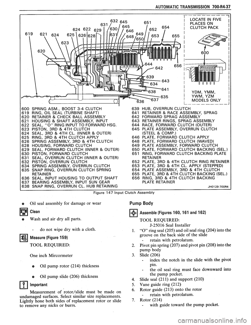
Figure 147 Input Clutch Assembly
e Oil seal assembly for damage or wear Pump Body
Clean
e Wash and air dry all parts.
- do not wipe dry with a cloth.
Measure (Figure 159)
TOOL REQUIRED:
One inch Mircormeter
e Oil pump rotor (214) thickness
Oil pump slide (206) thickness
Important Assemble
(Figures 160, 161 and 162)
TOOL REQUIRED:
J-250 16 Seal Installer
1.
"0" ring seal (205) and oil seal ring (204) into the
groove on the back side of the slide
- retain with petrolatum.
2. Pivot
pin spring (207) and pivot pin (208) into the
pump body
3. Slide (206)
- index the notch in the slide with the pivot
pin.
- the oil seal ring must face downward into
the pump pocket.
4. Slide seal
(2 1 1) and support (2 10)
5. Vane guide ring (2 12)
Measurement of
rotor/slide must be made on 6.
Rotor
guide (213) onto the rotor
undamaged surfaces. Select similar size replacements.
- retain with petrolatum.
Lightly hone both sides of replacement rotor or
slide 7. Rotor (214)
to remove any nicks or burrs. - with guide toward the pump pocket.
Page 1089 of 1825
700-R4-38 AUTOMATIC TRANSMISSION
ILL.
NO. DESCRIPTION
605 HOUSING & DRUM ASSEMBLY, REVERSE
INPUT CLUTCH
607 PISTON ASM., REVERSE INPUT CLUTCH
608 SEALS, REVERSE INPUT CLUTCH
(INNER
& OUTER)
609 SPRING ASM., REVERSE INPUT CLUTCH
610 RING, REVERSE INPUT CLUTCH SPRING
RETAINER
6
1 1 PLATE, REVERSE INPUT CL. (BELLEVILLE) 61 2 PLATE ASM., REVERSE INPUT CLUTCH
613 PLATE, REVERSE INPUT CLUTCH BACKING
614 RING, REVERSE INPUT CL. RETAINING
Figure 148 Reverse lnput Clutch Assembly Figure
149 Reverse
lnput Retainer Ring - Removal
A CHECK FOR DISHING AT
THIS POINT
605 HOUSING & DRUM ASSEMBLY, REVERSE INPUT CLUTCH JH0132-700R4
Figure 150 Check Reverse lnput Housing For Dishing
8. Vanes (2 1 5)
9
. Vane guide ring (2 12)
10. Pump slide spring (209)
11. Oil seal assembly
(2), retainer (94).
- use J-25016
Oil Pump Cover
Assemble (Figures 160 and 163)
1. Pressure relief ball (231), spring (232) and rivet
(230)
Inner (229) and outer (228) converter clutch
valve springs into the converter clutch valve bore
Converter clutch valve (227)
Stop valve (226)
Retaining ring (225)
Pressure regulator valve (2 18) into the pressure
regulator bore
Pressure regulator valve spring (219)
T.V. boost valve (222) into the T.V. bushing
- long land of the valve into the large hole of
the bushing.
- retain with petrolatum.
Reverse boost valve (220) into the reverse boost
valve sleeve
- small end of the valve first.
Page 1090 of 1825
AUTOMATIC TRANSMISSION 700-R4-39
CHECK FOR (.040" - .075")
BACKING PLATE
TRAVEL. / /
Figure 15 1 ~everse lnput Backing Plate Selection
REVERSE INPUT CLUTCH
I NO. I THICKNESS
FLAT STEEL
2.045mm (.081")
CLUTCH PLATE 1.892mm (.075")
COMPOSITION
FACED CLUTCH 1.880mm (.074")
PLATE 1.730mm (.068")
BELLEVILLE 2.31 1mm (.0911')
PLATE 2.210mm (.087") --
BACKING PLATE I 1 I SELECTIVE
-- Figure 152 Reverse Input Clutch Plate Chart
- retain with petrolatum.
10. Reverse boost
valve sleeve (221) into the pressure
regulator bore
11. T.V. boost
valve sleeve (223) into the pressure
regulator bore
12. Retainer ring (224)
Oil Pump Cover and Body
Assemble (Figures 160, 164, 165 and 166)
TOOLS REQUIRED:
J-21368 Oil Pump Body and Cover
Alignment Band
1. Oil pump cover (2
17) onto oil pump body
- stator shaft through a bench hole.
2. Pump cover bolts (236)
BACKING PLATE TRAVEL = 1.02rnrn - 1.94mm
7.60mrn - 7.45rnm
JH0191-700R4
Figure 152A Reverse lnput Backing Plate Selection
Chart
605 HOUSING
& DRUM ASSEMBLY, REVERSE
INPUT CLUTCH
607 PISTON ASM., REVERSE INPUT CLUTCH
609 SPRING ASM., REVERSE INPUT CLUTCH
610 RING, REVERSE INPUT CLUTCH SPRING
RETAINER
61
1 PLATE, REVERSE INPUT CL. (BELLEVILLE)
61 2 PLATE ASM., REVERSE INPUT CLUTCH
61
3 PLATE, REVERSE INPUT CLUTCH BACKING
614 RING, REVERSE INPUT CL. RETAINING
Figure 153 Reverse lnput Clutch
- leave finger tight.
3. Align
pump cover and pump body with J-21368.
- place a screwdriver through a bolt hole and
into a hole in the bench.
4. Torque attaching bolts to 22
N.m (18 ft. lbs.)
5. Pump to case gasket (009) onto case
- retain with petrolatum.
6. Oil seal rings
(233), if removed previously, onto
the pump cover hub
- retain with petrolatum.
7. Pump to case oil seal (008)
Page 1091 of 1825
700-W4-40 AUTOMATIC TRANSMISSION
ILL.
NO. BESCW IPTIBN
615 BEARING ASSEMBLY, STATOR SHAFT/
SELECTIVE WASHER
616 WASHER, THRUST (SELECTIVE)
621 HOUSING & SHAFT ASSEMBLY, INPUT A
BAND ANCHOR PIN LOCATION
10 CASE, TRANSMISSION
48 PIN, BAND ANCHOR
605 HOUSING & DRUM ASSEMBLY, REVERSE
INPUT CLUTCH
621 HOUSING &SHAFT ASSEMBLY, INPUT
JH0137-700R4
Figure 154 Thrust Bearing and Selective Washer
Location Figure 156 Installirlg lnput
Clutch
605 HOUSING & DRUM ASSEMBLY, REVERSE I INPUT Cl-VTCH I
615 BEARING ASSEMBLY, STATOR SHAFT/ 1 SELECTIVE WASHER
616 WASHER THRUST (SELECTIVE)
Figure
155 Reverse lnput and lnput Clutches
CASE, TRANSMISSION BAND ASSEMBLY, 2-4
HOUSING & DRUM ASSEMBLY, REVERSE
I
INPUT CLUTCH JH0138-700R4 I
Figure 157 2-4 Band Assembly - Installed
- do not twist the seal.
- lubricate with transmission fluid.
8. Thrust washer (601)
Install or Connect (Figure 167)
TOOLS REQUIRED:
5-25025-1 Alignment Pins
1. 5-25025-1 into the case as shown
2.
Oil pump assembly into the case
- align all holes properly.
3. Bolts and washers (5 and 6)
Page 1093 of 1825
700-R4-42 AUTOMATIC TRANSMISSION
ILL.
NO.
Figure 160 Oil Puml
DESCRIPTION
SEAL ASSEMBLY, OIL
BUSHING, PUMP BODY
RETAINER, FRONT HELIX SEAL
TUBE, AUXILIARY ACCUMULATOR VAI
BODY, PUMP
RING, OIL SEAL (SLIDE TO
WEAR PLATE)
SEAL,
"0" RING (SLIDE SEAL
BACK-UP)
SLIDE, PUMP
SPRING, PIVOT PIN
PIN, PIVOT SLlDE
SPRING, PUMP SLlDE (OUTER)
SUPPORT, PUMP SLlDE SEAL
SEAL, PUMP SLlDE
RING, PUMP VANE
GUIDE, ROTOR
ROTOR, OIL PUMP
VANE, PUMP
SHAFT, STATOR
COVER, PUMP
VALVE, PRESSURE REGULATOR
SPRING, PRESSURE REGULATOR
VALVE
VALVE, REVERSE BOOST
SLEEVE, REVERSE BOOST VALVE
VALVE, T.V. BOOST
BUSHING, T.V. BOOST
RING, OIL PUMP REVERSE BOOST
VALVE RETAINING
RING, OIL PUMP CONVERTER CLUTCH
VALVE RETAINING
VALVE, STOP
VALVE. CONVERTER CLUTCH
SPRING,
CONVERTER CLUTCH
VALVE (OUTER)
SPRING, CONVERTER CLUTCH
VALVE (INNER)
RIVET, PRESSURE RELIEF BOLT
BALL, PRESSURE RELIEF
SPRING, PRESSURE RELIEF
RING, OIL SEAL (STATOR SHAFT)
SEAL, OIL PUMP COVER SCREEN
SCREEN, OIL PUMP COVER
BOLT,
M8 x 1.25 x 40 (COVER
TO BODY)
PLUG, OIL PUMP AIR BLEED
PLUG, OIL PUMP COVER
PLUG, OIL PUMP COOLER FEED
PLUG, OIL PUMP CONVERTER
CLUTCH SIGNAL
RETAINER
& BALL ASSEMBLY,
PUMP COVER
SCREW, STATOR SHAFT (M6
x 1 x 16.0)
SPRING, PUMP SLlDE (INNER)