1988 PONTIAC FIERO automatic transmission
[x] Cancel search: automatic transmissionPage 1077 of 1825
700-84-26 AUTOMATIC TRANSMISSION
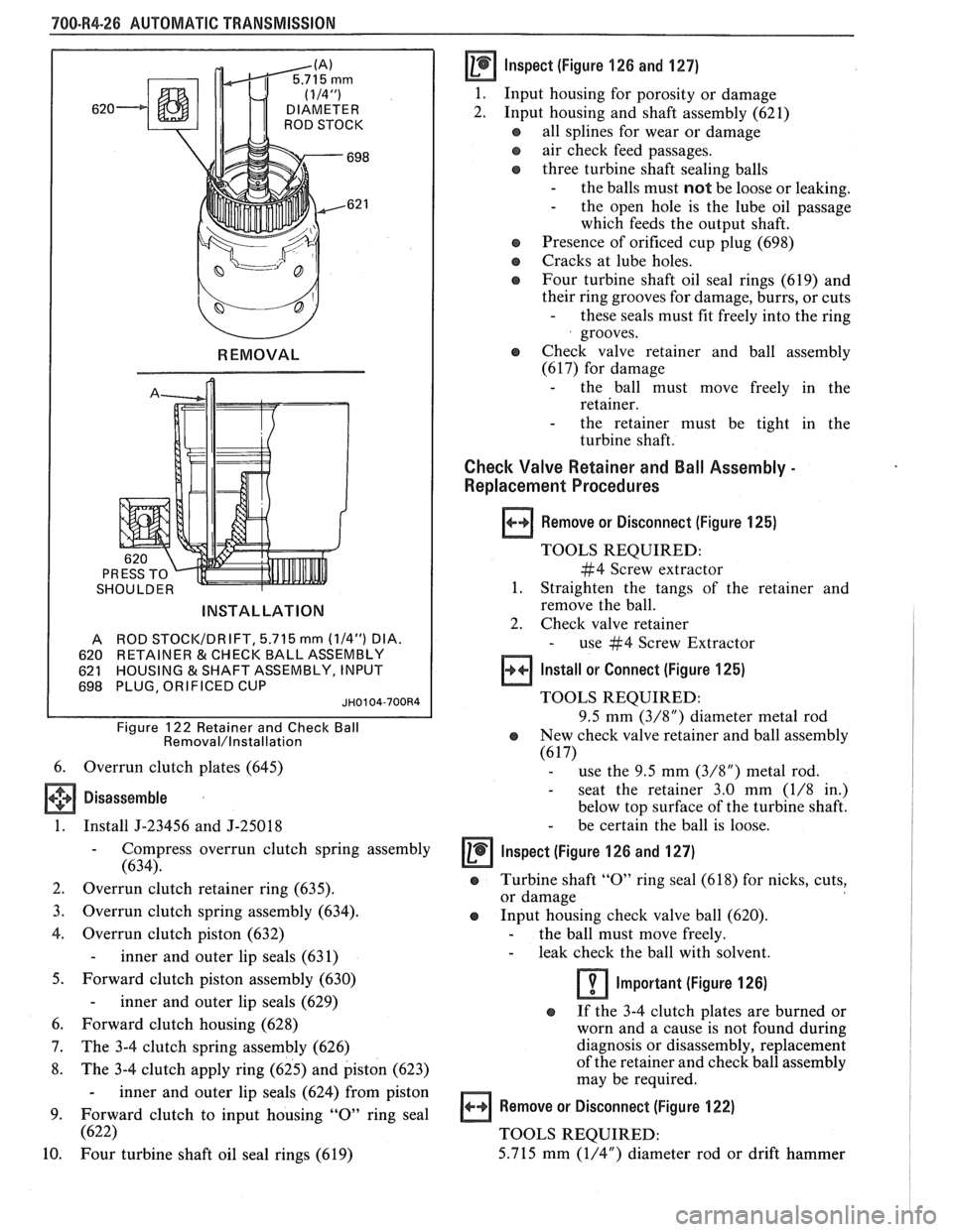
SHOULDER
INSTALLATION
A ROD STOCI
620 RETAINER
& CHECK BALL ASSEMBLY
621 HOUSING
& SHAFT ASSEMBLY, INPUT
698 PLUG, ORIFICED CUP JH0104-700R4
Figure 122 Retainer and Check Ball Removal/lnstallation
6. Overrun clutch plates (645)
Disassemble
1. Install J-23456 and J-25018
- Compress overrun clutch spring assembly
(634).
2. Overrun clutch retainer ring (635).
3. Overrun clutch spring assembly (634).
4. Overrun clutch piston (632)
- inner and outer lip seals (631)
5. Forward clutch piston assembly (630)
- inner and outer lip seals (629)
6. Forward clutch housing (628)
7. The 3-4 clutch spring assembly (626)
8. The 3-4 clutch apply ring (625) and piston (623)
- inner and outer lip seals (624) from piston
9. Forward clutch to input housing
"0" ring seal
(622)
10.
Four turbine shaft oil seal rings (619)
Inspect (figure 126 and 127)
1.
Input housing for porosity or damage
2. Input housing and shaft assembly (621)
all splines for wear or damage
e air check feed passages.
three turbine shaft sealing balls
- the balls must not be loose or leaking. - the open hole is the lube oil passage
which feeds the output shaft.
a Presence of orificed cup plug (698)
a Cracks at lube holes.
@ Four turbine shaft oil seal rings (619) and
their ring grooves for damage, burrs, or cuts
- these seals must fit freely into the ring
grooves.
o Check valve retainer and ball assembly
(617) for damage
- the ball must move freely in the
retainer.
- the retainer must be tight in the
turbine shaft.
Check Valve Retainer and Ball Assembly -
Replacement Procedures
Remove or Disconnect (Figure 125)
TOOLS REQUIRED:
#4 Screw extractor
1. Straighten the tangs of the retainer and
remove the ball.
2. Check valve retainer
- use #4 Screw Extractor
Install or Connect (Figure 125)
TOOLS REQUIRED:
9.5 mm
(3/8") diameter metal rod
e New check valve retainer and ball assembly
(6 17) - use the 9.5 mm (3/8") metal rod.
- seat the retainer 3.0 mm (1/8 in.)
below top surface of the turbine shaft.
- be certain the ball is loose.
lnspect (Figure 126 and 127)
@ Turbine shaft "0" ring seal (61 8) for nicks, cuts,
or damage
Input housing check valve ball (620).
- the ball must move freely. - leak check the ball with solvent.
Important (Figure 126)
o If the 3-4 clutch plates are burned or
worn and a cause is not found during
diagnosis or disassembly, replacement
of the retainer and check ball assembly
may be required.
Remove or Disconnect (Figure 122)
TOOLS REQUIRED:
5.715 mm
(1/4") diameter rod or drift hammer
Page 1078 of 1825
AUTOMATIC TRANSMISSION '900-R4-27
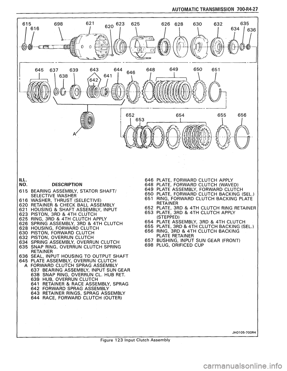
ILL. NO. DESCRIPTION
61 5 BEARING ASSEMBLY, STATOR SHAFT/ SELECTIVE WASHER
61 6 WASHER, THRUST (SELECTIVE)
620 RETAINER
& CHECK BALL ASSEMBLY
621 HOUSING & SHAFT ASSEMBLY, INPUT
623 PISTON, 3RD & 4TH CLUTCH
625 RING, 3RD & 4TH CLUTCH APPLY
626 SPRING ASSEMBLY, 3RD & 4TH CLUTCH
628 HOUSING, FORWARD CLUTCH
630 PISTON, FORWARD CLUTCH
632 PISTON, OVERRUN CLUTCH
634 SPRING ASSEMBLY, OVERRUN CLUTCH
635 SNAP RING, OVERRUN CLUTCH SPRING
RETAINER
636 SEAL, INPUT HOUSING TO OUTPUT SHAFT
645 PLATE ASSEMBLY, OVERRUN CLUTCH
A FORWARD CLUTCH SPRAG ASSEMBLY
637 BEARING ASSEMBLY, INPUT SUN GEAR
638 SNAP RING, OVERRUN CL. HUB RET.
639 HUB, OVERRUN CLUTCH
641 RETAINER
& RACE ASSEMBLY, SPRAG
642 FORWARD SPRAG ASSEMBLY
643 RETAINER RINGS, SPRAG ASSEMBLY
644 RACE, FORWARD CLUTCH (OUTER) 646
PLATE, FORWARD CLUTCH APPLY
648
PLATE, FORWARD CLUTCH (WAVED)
649 PLATE ASSEMBLY, FORWARD CLUTCH
650 PLATE, FORWARD CLUTCH BACKING
(SEL.) 651 RING, FORWARD CLUTCH BACKING PLATE
RETAINER
652 PLATE. 3RD
& 4TH CLUTCH RING RETAINER
653 PLATE; 3RD & 4TH CLUTCH APPLY ISTEPPED)
654 KATE ASSEMBLY, 3RD & 4TH CLUTCH
655 PLATE, 3RD & 4TH CLUTCH BACKING (SEL.) 656 RING, 3RD & 4TH CLUTCH BACKING
PLATE RETAINER
657 BUSHING, INPUT SUN GEAR (FRONT)
698 PLUG,
ORIFICED CUP
Figure 123 Input Clutch Assembly
Page 1079 of 1825
700-R4-28 AUTOMATIC TRANSMISSION
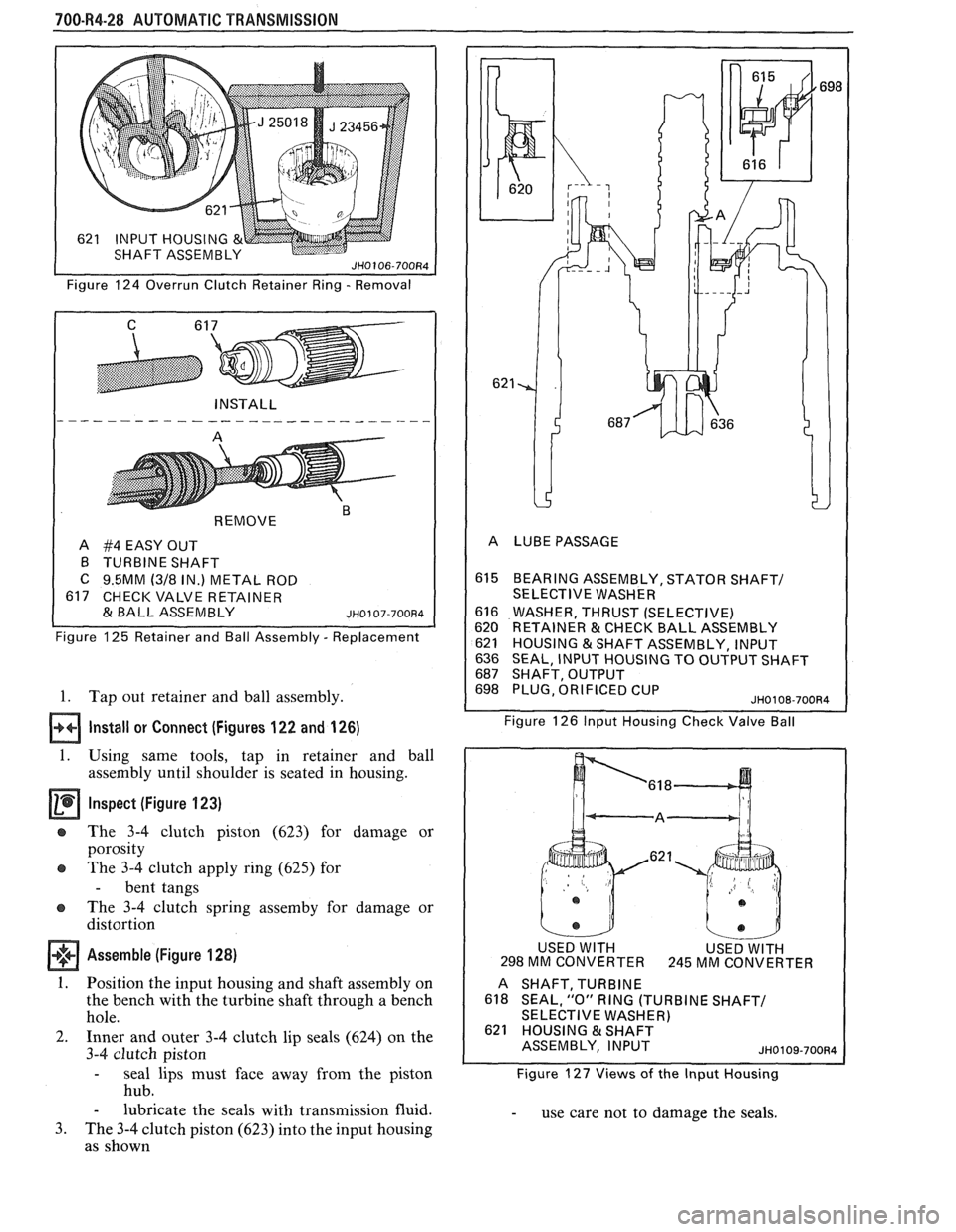
Figure 124 Overrun Clutch Retainer Ring - Removal
REMOVE
"
A #4 EASY OUT
B TURBINE SHAFT
C 9.5MM (318 IN.) METAL ROD
617 CHECK VALVE RETAINER
& BALL ASSEMBLY ~~0107-700~4
Figure 125 Retainer and Ball Assembly - Replacement
1. Tap out retainer and ball assembly.
Install or Connect (Figures 122 and 126)
1. Using same tools, tap in retainer and ball
assembly until shoulder is seated in housing.
Inspect (Figure 123)
e The 3-4 clutch piston (623) for damage or
porosity
e The 3-4 clutch apply ring (625) for
- bent tangs
The 3-4 clutch spring
assemby for damage or
distortion
Assemble (Figure 128)
1. Position the input housing and shaft assembly on
the bench with the turbine shaft through a bench
hole.
2. Inner and outer 3-4 clutch lip seals (624) on the
3-4 clutch piston
- seal lips must face away from the piston
hub.
- lubricate the seals with transmission fluid.
3. The 3-4 clutch piston (623) into the input housing
as shown
615 BEARlNGASSEMBLY,STATORSHAFT/
SELECTIVE WASHER
616 WASHER, THRUST (SELECTIVE)
620 RETAINER & CHECK BALL ASSEMBLY
621 HOUSING &SHAFT ASSEMBLY, INPUT
636 SEAL, INPUT HOUSING TO OUTPUT SHAFT 687 SHAFT, OUTPUT 698 PLUG, ORIFICED CUP JH0108-70084
Figure 126 lnput Housing Check Valve Ball
USED
WlTH MM CONVERTER
.621
USED WITH 245 MM CONVER
TER
A
SHAFT,TURBINE
618 SEAL, "0" RING (TURBINE SHAFT/ SELECTIVE WASHER) 621 HOUSING & SHAFT
ASSEMBLY, INPUT
JH0109-70084
Figure 127 Views of the lnput Housing
- use care not to damage the seals.
Page 1080 of 1825
AUTOMATIC TRANSMISSION "/O-R4-29
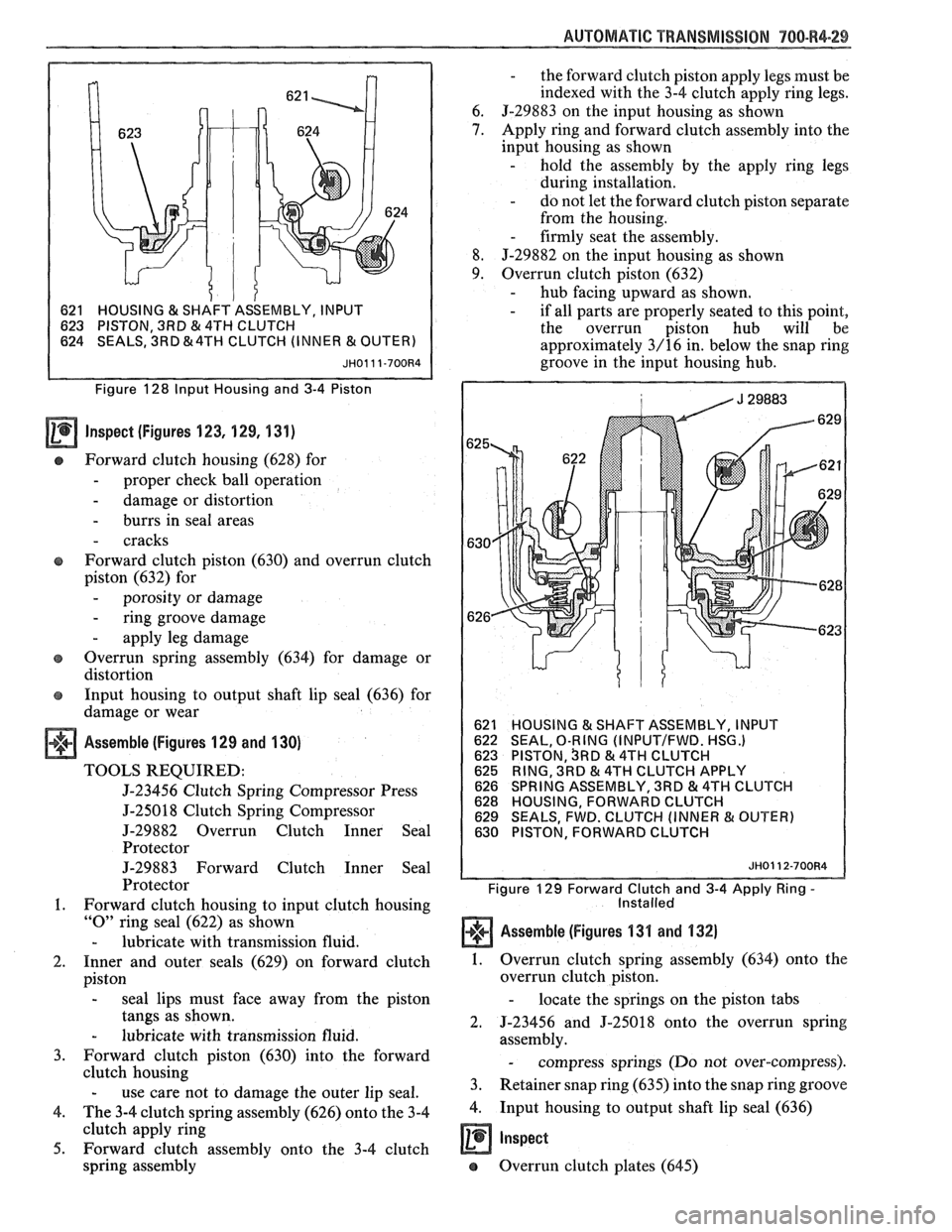
1 621 HOUSING & SHAFT
ASSEMBLY, INPUT
623 PISTON, 3RD
& 4TH CLUTCH
624 SEALS, 3RD &4TH CLUTCH (INNER & OUTE
Figure 128 Input Housing and 3-4 Piston
Inspect (figures 123, 129, 131)
Forward clutch housing (628) for
- proper check ball operation
- damage or distortion
- burrs in seal areas
- cracks
Forward clutch piston
(630) and overrun clutch
piston
(632) for
- porosity or damage
- ring groove damage
- apply leg damage
e Overrun spring assembly (634) for damage or
distortion
e Input housing to output shaft lip seal (636) for
damage or wear
Assemble (Figures 129 and 130)
TOOLS REQUIRED:
5-23456 Clutch Spring Compressor Press
5-25018 Clutch Spring Compressor
J-29882 Overrun Clutch Inner Seal
Protector
J-29883 Forward Clutch Inner Seal
Protector
1. Forward clutch housing to input clutch housing
"0" ring seal (622) as shown
- lubricate with transmission fluid.
2. Inner and outer seals (629) on forward clutch
piston
- seal lips must face away from the piston
tangs as shown.
- lubricate with transmission fluid.
3. Forward clutch piston (630) into the forward
clutch housing
- use care not to damage the outer lip seal.
4. The 3-4 clutch spring assembly (626) onto the 3-4
clutch apply ring
5. Forward clutch assembly onto the 3-4 clutch
spring assembly
- the forward clutch piston apply legs must be
indexed with the 3-4 clutch apply ring legs.
6.
J-29883 on the input housing as shown
7. Apply ring and forward clutch assembly into the
input housing as shown
- hold the assembly by the apply ring legs
during installation.
- do not let the forward clutch piston separate
from the housing.
- firmly seat the assembly.
8. J-29882 on the input housing as shown
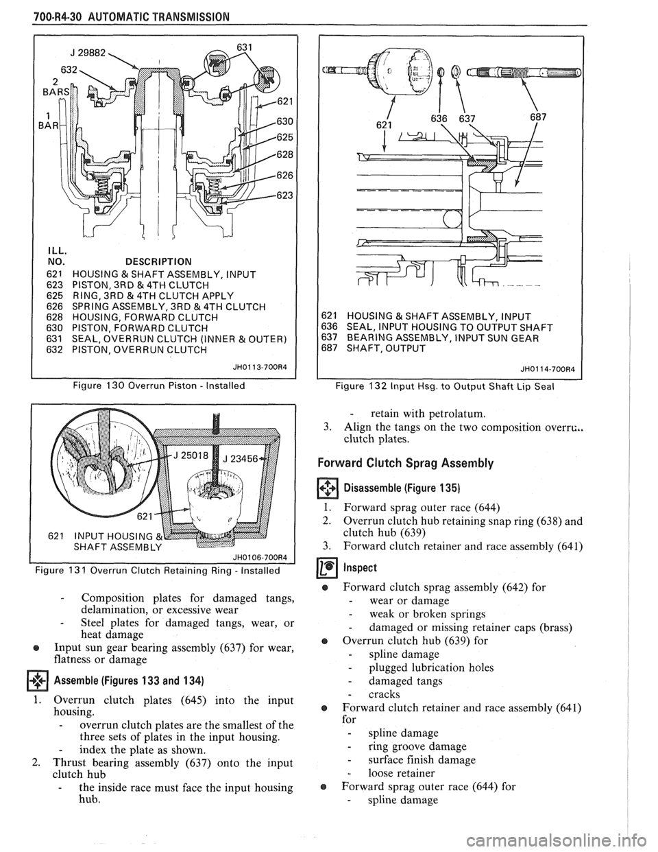
9. Overrun clutch piston (632) - hub facing upward as shown. - if all parts are properly seated to this point,
the overrun piston hub will be
approximately
3/16 in. below the snap ring
groove in the input housing hub.
HOUSING 13( SHAFT ASSEMBLY, INPUT
SEAL, O-RING (INPUTIFWD. HSG.) PISTON, SRD & 4TH CLUTCH
RING, 3RD & 4TH CLUTCH APPLY
SPRING ASSEMBLY, 3RD & 4TH CLUTCH
HOUSING, FORWARD CLUTCH
SEALS, FWD. CLUTCH (INNER
& OUTER)
PISTON, FORWARD CLUTCH
JH0112-700R4
Figure 129 Forward Clutch and 3-4 Apply Ring - Installed
Assemble (Figures 1311 and 132)
1. Overrun clutch spring assembly (634) onto the
overrun clutch piston.
- locate the springs on the piston tabs
2. 5-23456 and J-25018 onto the overrun spring
assembly.
- compress springs (Do not over-compress).
3. Retainer snap ring (635) into the snap ring groove
4. Input housing to output shaft lip seal (636)
a Inspect
e Overrun clutch plates (645)
Page 1081 of 1825
700-R4-30 AUTOMATIC TRANSMISSION
ILL.
NO.
62
1
623 625
626
628
630
63
1 632 DESCRIPTION
HOUSING
& SHAFT ASSEMBLY, INPUT
PISTON, 3RD
& 4TH CLUTCH
RING, 3RD
81 4TH CLUTCH APPLY
SPRING ASSEMBLY, 3RD & 4TH CLUTCH
HOUSING, FORWARD CLUTCH
PISTON, FORWARD CLUTCH
SEAL, OVERRUN CLUTCH (INNER
& OUTER)
PISTON, OVERRUN CLUTCH
JH0113-700R4
Figure 130 Overrun Piston - Installed
Figure 13
1 Overrun Clutch Retaining Ring - Installed
- Composition plates for damaged tangs,
delamination, or excessive wear
- Steel plates for damaged tangs, wear, or
heat damage
@ Input sun gear bearing assembly (637) for wear,
flatness or damage
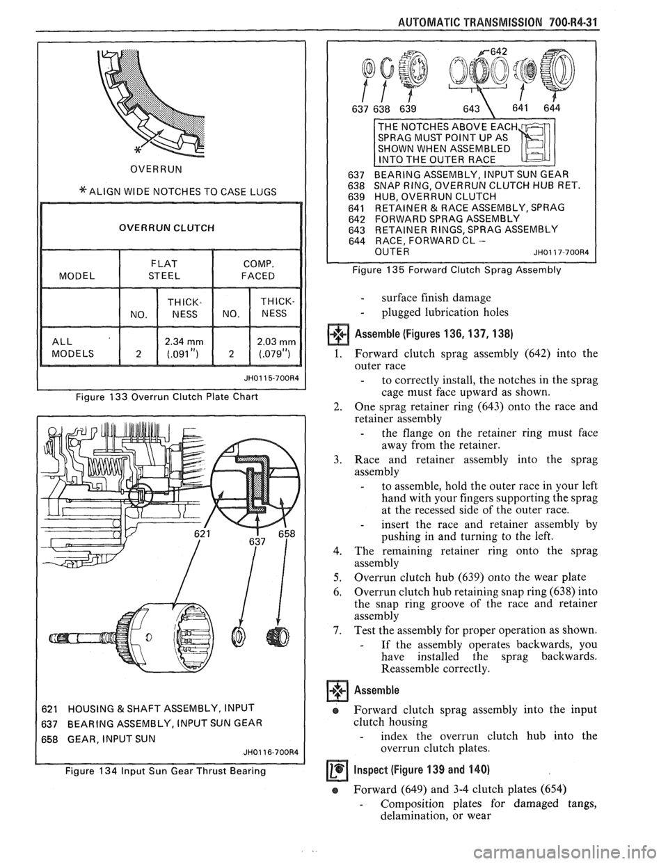
Assemble (Figures 133 and 134)
1. Overrun clutch plates (645) into the input
housing.
- overrun clutch plates are the smallest of the
three sets of plates in the input housing.
- index the plate as shown.
2. Thrust bearing assembly (637) onto the input
clutch hub
- the inside race must face the input housing
hub.
621 HOUSING & SHAFT ASSEMBLY, INPUT
636 SEAL, INPUT HOUSING TO OUTPUT SHAFT
637 BEARING ASSEMBLY, INPUT SUN GEAR
687 SHAFT, OUTPUT
JH0114-700R4
Figure 132 Input Hsg. to Output Shaft Lip Seal
- retain with petrolatum.
3. Align the tangs on the two composition
overrc.,
clutch plates.
Forward Clutch Sprag Assembly
Disassemble (Figure 135)
1.
Forward sprag outer race (644)
2. Overrun clutch hub retaining snap ring (638) and
clutch hub (639)
3. Forward clutch retainer and race assembly (641)
Inspect
@ Forward clutch sprag assembly (642) for
- wear or damage
- weak or broken springs
- damaged or missing retainer caps (brass)
@ Overrun clutch hub (639) for
- spline damage
- plugged lubrication holes
- damaged tangs
- cracks
o Forward clutch retainer and race assembly (641)
for
- spline damage
- ring groove damage
- surface finish damage
- loose retainer
o Forward sprag outer race (644) for
- spline damage
Page 1082 of 1825
AUTOMATIC TRANSMISSION 700.R4-31
OVERRUN
*ALIGN WIDE NOTCHES TO CASE LUGS
I OVERRUN CLUTCH I
I I Figure 133 Overrun Clutch Plate Chart
621 HOUSING
& SHAFT
ASSEMBLY, INPUT
637 BEARING
ASSEMBLY, INPUT SUN GEAR
658 GEAR, INPUT SUN
Figure 134 Input Sun Gear Thrust Bearing 641
RETAINER & RACE ASSEMBLY, SPRAG
642 FORWARD SPRAG ASSEMBLY
INER RINGS, SPRAG ASSEMBLY
FORWARD CL -
Figure 135 Forward Clutch Sprag Assembly
- surface finish damage
- plugged lubrication holes
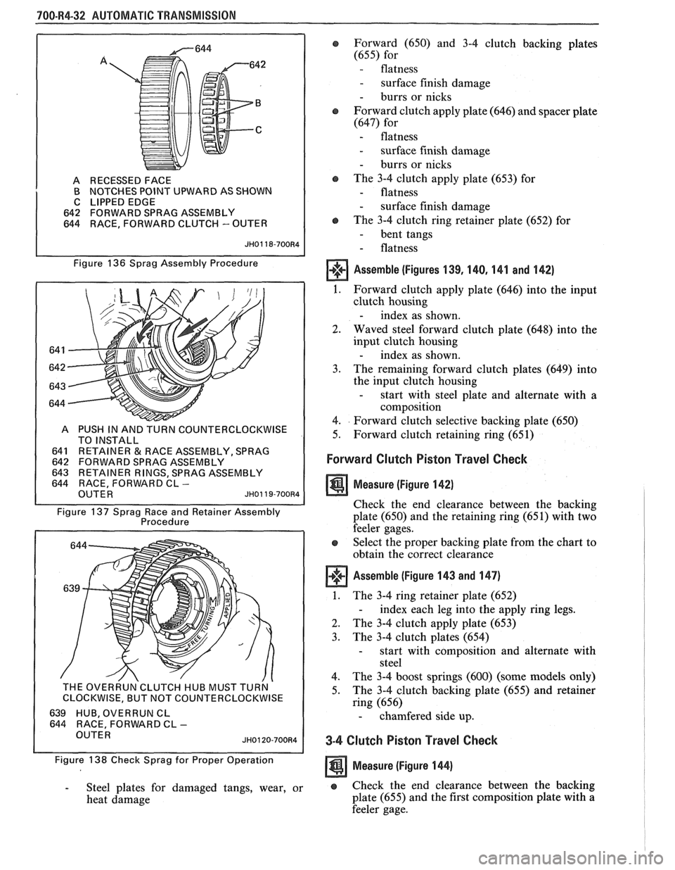
Assemble (Figures 136,137,138)
1. Forward clutch sprag assembly (642) into the
outer race
- to correctly install, the notches in the sprag
cage must face upward as shown.
2. One sprag retainer ring (643) onto the race and
retainer assembly
- the flange on the retainer ring must face
away from the retainer.
3. Race and retainer assembly into the sprag
assembly
- to assemble, hold the outer race in your left
hand with your fingers supporting the sprag
at the recessed side of the outer race.
- insert the race and retainer assembly by
pushing in and turning to the left.
4. The remaining retainer ring onto the sprag
assembly
5. Overrun
clutch hub (639) onto the wear plate
6. Overrun
clutch hub retaining snap ring (638) into
the snap ring groove of the race and retainer
assembly
7. Test the assembly for proper operation as shown.
- If the assembly operates backwards, you
have installed the sprag backwards.
Reassemble correctly.
Assemble
e Forward clutch sprag assembly into the input
clutch housing
- index the overrun clutch hub into the
overrun clutch plates.
Inspect (figure 139 and 140) -
Forward (649) and 3-4 clutch plates (654)
- Composition plates for damaged tangs,
delamination, or wear
Page 1083 of 1825
700-R4-32 AUTOMATIC TRANSMISSION
A RECESSED FACE
B NOTCHES POINT UPWARD AS SHOWN
C LIPPED EDGE
642 FORWARD SPRAG ASSEMBLY
644 RACE, FORWARD CLUTCH
- OUTER
Figure 136 Sprag Assembly Procedure
COUNTERCLOCKWISE
641
RETAlNER&RACEASSEMBLY,SPRAG 642 FORWARD SPRAG ASSEMBLY
INER RINGS, SPRAG ASSEMBLY
FORWARD CL -
Figure 137 Sprag Race and Retainer Assembly
Procedure
THE OVERRUN'CLUTCH HUB MUST TURN '
I CLOCKWISE, BUT NOT COUNTERCLOCKWISE I
639 HUB, OVERRUN CL
644 RACE, FORWARD CL - OUTER JH0120-700R4
Figure 138 Check Sprag for Proper Operation
- Steel plates for damaged tangs, wear, or
heat damage
e Forward (650) and 3-4 clutch backing plates
(655) for
- flatness
- surface finish damage
- burrs or nicks
Forward clutch apply plate (646) and spacer plate
(647) for
- flatness
- surface finish damage
- burrs or nicks
@ The 3-4 clutch apply plate (653) for
- flatness
- surface finish damage
o The 3-4 clutch ring retainer plate (652) for
- bent tangs
- flatness
Assemble (Figures 139, 140, 141 and 142)
1. Forward clutch apply plate (646) into the input
clutch housing
- index as shown.
2. Waved steel forward clutch plate (648) into the
input clutch housing
- index as shown.
3. The
remaining forward clutch plates (649) into
the input clutch housing
- start with steel plate and alternate with a
composition
4. Forward clutch selective backing plate (650)
5. Forward clutch retaining ring (651)
Forward Clutch Piston Travel Check
Measure (Figure 142)
Check the end clearance between the backing
plate (650) and the retaining ring (65 1) with two
feeler gages.
Select the proper backing plate from the chart to
obtain the correct clearance
Assemble (Figure 143 and 147)
1. The 3-4 ring retainer plate (652)
- index each leg into the apply ring legs.
2. The 3-4 clutch apply plate (653)
3. The
3-4 clutch plates (654)
- start with composition and alternate with
steel
4. The 3-4 boost springs (600) (some models only)
5. The
3-4 clutch backing plate (655) and retainer
ring (656)
- chamfered side up.
3-4 Clutch Piston Travel Check
Measure (Figure 144)
e Check the end clearance between the backing
plate (655) and the first composition plate with
a
feeler gage.
Page 1084 of 1825
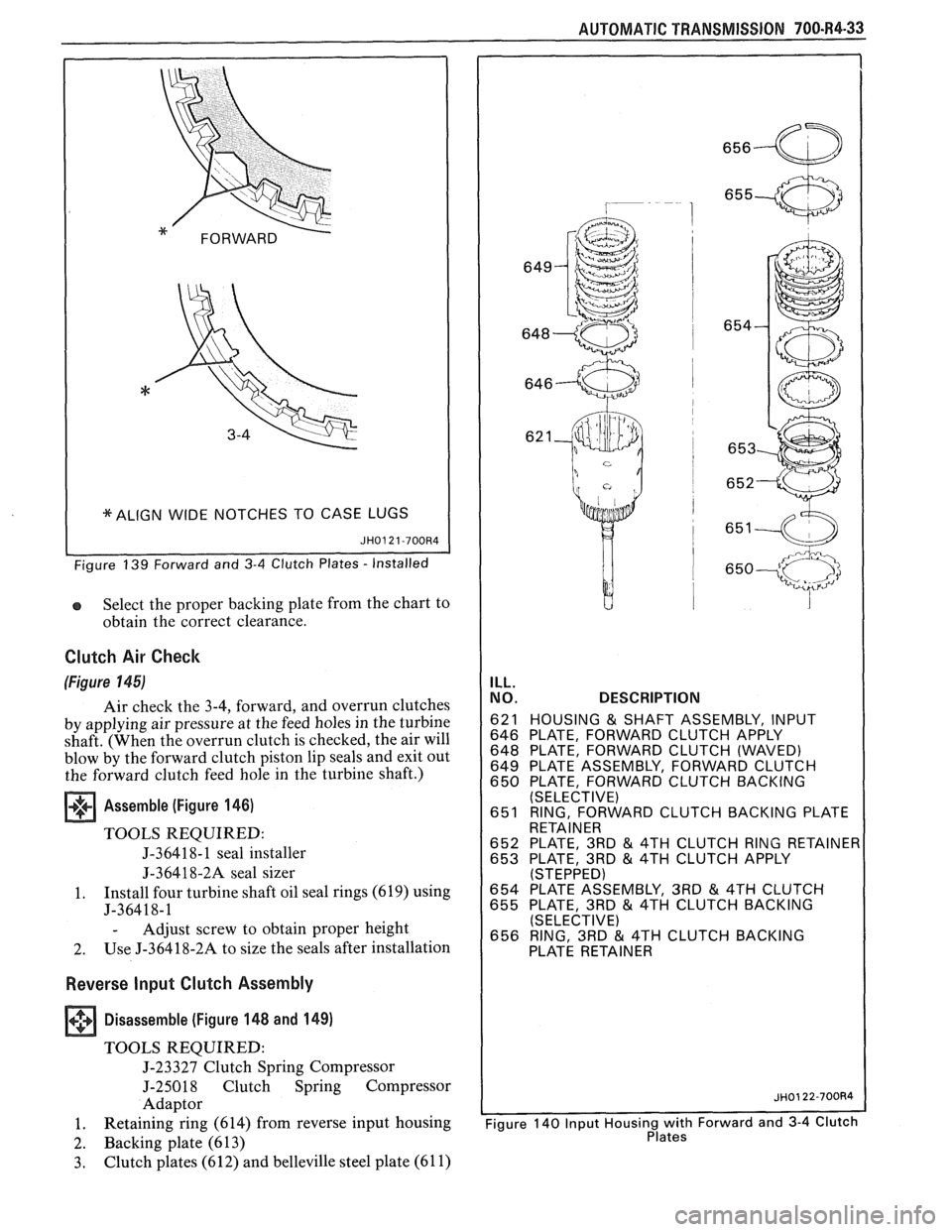
I *ALIGN WIDE NOTCHES TO CASE LUGS (
Select the proper backing plate from the chart to
obtain the correct clearance.
Clutch Air Check
(Figure 145)
Air check the 3-4, forward, and overrun clutches
by applying air pressure at the feed holes in the turbine
shaft. (When the overrun clutch is checked, the air will
blow by the forward clutch piston lip seals and exit out
the forward clutch feed hole in the turbine shaft.)
Assemble (Figure 146)
TOOLS REQUIRED:
J-36418- 1 seal installer
J-36418-2A seal sizer
1. Install four turbine
shaft oil seal rings (619) using
J-36418-1
- Adjust screw to obtain proper height
2. Use
J-36418-2A to size the seals after installation
Reverse Input Clutch Assembly
+++ Disassemble (Figure 148 and 149) [I]
TOOLS REQUIRED:
J-23327 Clutch Spring Compressor
J-25018 Clutch Spring Compressor
Adaptor
1. Retaining
ring (614) from reverse input housing
2. Backing plate (613)
3. Clutch plates (612) and belleville steel plate (61 1)
AUTOMATIC TRANSMISSION 700-R4-33
ILL.
NO. DESCRIPTION
621 HOUSING & SHAFT ASSEMBLY, INPUT
646 PLATE, FORWARD CLUTCH APPLY
648 PLATE, FORWARD CLUTCH (WAVED)
649 PLATE ASSEMBLY, FORWARD CLUTCH
650 PLATE, FORWARD CLUTCH BACKING
(SELECTIVE)
651 RING, FORWARD CLUTCH BACKING PLATE
RETAINER
652 PLATE, 3RD
& 4TH CLUTCH RING RETAINE 653 PLATE, 3RD & 4TH CLUTCH APPLY (STEPPED) 654 PLATE ASSEMBLY, 3RD & 4TH CLUTCH
655 PLATE, 3RD & 4TH CLUTCH BACKING
(SELECTIVE)
656 RING, 3RD
& 4TH CLUTCH BACKING