Page 1103 of 1825

700-R4-52 AUTOMATIC TRANSMISSION
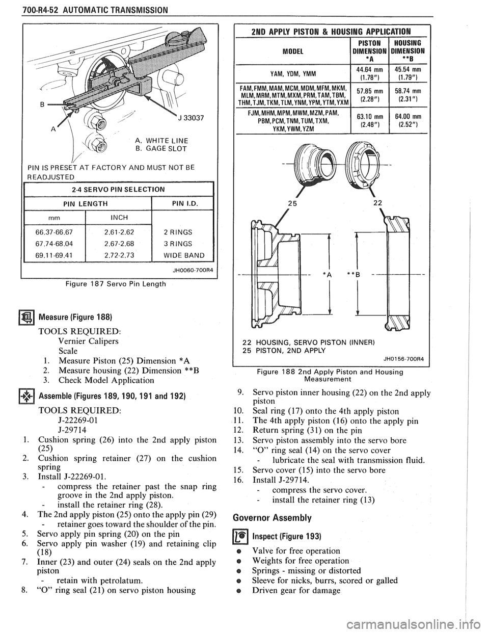
A. WHITE LINE B. GAGE SLOT
Figure 187 Servo Pin Length
Measure (Figure 188)
TOOLS REQUIRED:
Vernier Calipers
Scale
1. Measure Piston (25) Dimension
*A
2.
Measure housing (22) Dimension **B
3. Check Model Application
Assemble (Figures 189, 190, 191 and 192)
TOOLS REQUIRED:
5-22269-01
J-297 14
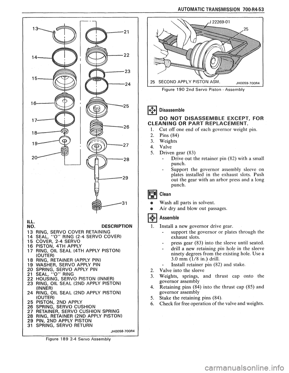
1. Cushion spring (26) into the 2nd apply piston
(25)
2. Cushion spring retainer (27) on the cushion
spring
3. Install J-22269-01.
- compress the retainer past the snap ring
groove in the 2nd apply piston.
- install the retainer ring (28).
4. The 2nd apply piston (25) onto the apply pin (29)
- retainer goes toward the shoulder of the pin.
5. Servo apply pin spring (20) on the pin
6. Servo apply pin washer (19) and retaining clip
(18)
7. Inner (23) and outer (24) seals on the 2nd apply
piston
- retain with petrolatum.
8. "0" ring seal (21) on servo piston housing
2ND APPLY PISTON & HOUSING APPLICATION
MODEL I DIMt!SION DIMENSION I **B I
I YAM, YOM, YMM I
MLM, MRM,MTM,MXM, PRM,TAM,TBM,
22 HOUSING, SERVO PISTON (INNER)
25 PISTON, 2ND APPLY
JH0156-700R4
Figure 188 2nd Apply Piston and Housing
Measurement
9. Servo piston inner housing (22) on the 2nd apply
piston
10. Seal ring (17) onto the 4th apply piston
11. The 4th apply piston (16) onto the apply pin
12. Return spring (31) on the pin
13. Servo piston assembly into the servo bore
14.
"0" ring seal (14) on the servo cover
- lubricate the seal with transmission fluid.
15. Servo cover (15) into the servo bore
16. Install J-297 14.
- compress the servo cover.
- install the retainer ring (13)
Governor Assembly
Inspect (Figure 193)
e Valve for free operation
e Weights for free operation
e Springs - missing or distorted
Sleeve for nicks, burrs, scored or galled
o Driven gear for damage
Page 1104 of 1825

ILL.
NO. DESCRlPTlON
13 RING, SERVO COVER RETAINING
14 SEAL, "0" RlNG (2-4 SERVO COVER)
15 COVER, 2-4 SERVO
16 PISTON. 4TH APPLY
17 RING, 811- SEAL (4TH APPLY PISTON)
(OUTER)
18 RING, RETAINER (APPLY PIN) 19 WASHER, SEWVO APPLY PIN
20 SPRING, SERVO APPLY PIN
21 SEAL, "0" RlNG 22 HOUSING, SERVO PISTON (INNER)
23 RING, OIL SEAL (2ND APPLY PISTON)
(INNER)
24 RING, OIL SEAL (2ND APPLY PISTON)
(OUTER)
29 PIN, ~NB APPLY PISTON
31 SPRING, SERVO RETURN
JH0058-700R4
AUTOMATIC TRANSMISSION 700-R4-53
SECOND APPLY PISTON ASM.
Figure
190 2nd Servo Piston - Assembly
Disassemble
DO NOT DISASSEMBLE EXCEPT, FOR
CLEANING
OR PART REPLACEMENT.
1. Cut off one end of each governor weight pin.
2. Pins (84)
3. Weights
4. Valve
5. Driven gear (83)
- Drive out the retainer pin (82) with a small
punch.
- Support the governor assembly sleeve on
plates installed in the exhaust slots. Push
out the gear with an arbor press and a long
punch.
e Wash all parts in solvent.
Air dry and blow out passages.
Assemble
1. Install a new governor drive gear.
- support the governor or plates through the
exhaust slots.
- press gear (83) into the sleeve until seated.
- drill a new retaining pin hole in the sleeve
ninety degrees from the existing hole. Use a
3.0
mm (1/8 in.) drill.
- Install retainer pin (82) and stake.
2. Valve into the sleeve
3. Weights, springs, and thrust cap onto the
governor assembly
4. Retaining
pins (84) into the thrust cap (85) and
governor assembly
5. Stake the retaining pins (84).
6. Check for free operation of the valve and weights.
Figure 189 2-4 Servo Assembly
Page 1105 of 1825
700-R4-54 AUTOMATIC TRANSMISSION
ILL.
NO. DESCRlPTlON
A CASE SERVO BORE
13 RING, SERVO COVER RETAINING
14 SEAL,
"0" RING (2-4 SERVO COVER)
15 COVER, 2-4 SERVO
16 PISTON, 4TH APPLY 17 RING, OIL SEAL (4TH APPLY PISTON)
(OUTER)
18-30 2ND APPLY PISTON ASSEMBLY
21 SEAL.
"0" RlNG
24 RING,' OIL SEAL (2ND APPLY PISTON) (OUTER)
31 SPRINGT~~ERVO RETURN
JH0057-700R4
Figure 19 1 2-4 Servo Bore Figure
192 Servo
Cover - Installed
GOVERNOR ASSEMBLY
A VALVE
B SECONDARY WEIGHT
C PRIMARY WEIGHT
D WEIGHT SPRING
E SLEEVE AND CARRIER
82 DRIVEN GEAR RETAINING PIN
83 DRIVEN GEAR
84 WEIGHT PINS
85 THRUST CAP
Figure 193 Governor Assembly
Install or Connect (Figures 193, 194)
1. Governor assembly (45) into the governor bore
2. Governor Cover (46)
- apply sealant, such as loctite cup plug
sealant
# 11 or equivalent to cover flange
before installation.
Page 1106 of 1825

AUTOMATIC TRANSMISSION 700-R4-55
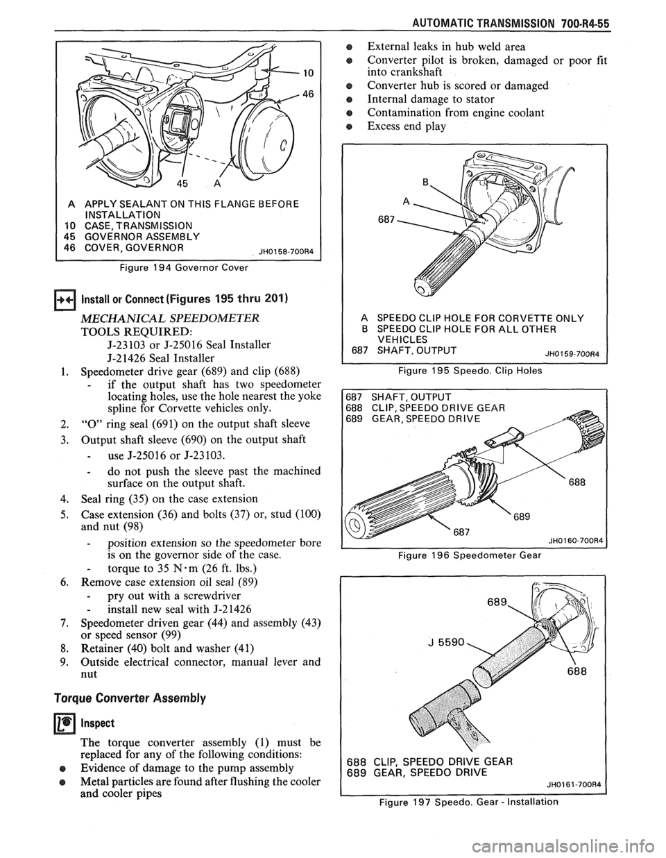
A APPLY SEALANT ON THIS FLANGE BEFORE
INSTALLATION
10 CASE TRANSMISSION
Figure
194 Governor Cover
Install or Connect (Figures 195 thru 201)
MECHANICAL SPEEDOMETER
TOOLS REQUIRED:
J-23 103 or J-25016 Seal Installer
J-21426 Seal Installer
1. Speedometer
drive gear (689) and clip (688)
- if the output shaft has two speedometer
locating holes, use the hole nearest the yoke
spline for Corvette vehicles only.
2. "0" ring seal (691) on the output shaft sleeve
3. Output shaft sleeve (690) on the output shaft
- use J-25016 or J-23103.
- do not push the sleeve past the machined
surface on the output shaft.
4. Seal
ring (35) on the case extension
5. Case extension
(36) and bolts
(37) or, stud (100)
and nut (98)
- position extension so the speedometer bore
is on the governor side of the case.
- torque to 35 N-m (26 ft. lbs.)
6. Remove case extension oil seal (89)
- pry out with a screwdriver
- install new seal with J-21426
7. Speedometer driven gear (44) and assembly (43)
or speed sensor (99)
8. Retainer (40) bolt and washer (41)
9. Outside
electrical connector, manual lever and
nut
Torque Converter Assembly
Inspect
The torque converter assembly (1) must be
replaced for any of the following conditions:
e Evidence of damage to the pump assembly
e Metal particles are found after flushing the cooler
and cooler pipes
a External leaks in hub weld area
e Converter pilot is broken, damaged or poor fit
into crankshaft
e Converter hub is scored or damaged
Internal damage to stator
e Contamination from engine coolant
a Excess end play
A SPEEDO CLlP HOLE FOR CORVETTE ONLY
B SPEEDO CLlP HOLE FOR ALL OTHER
VEHICLES
Figure
195 Speedo. Clip Holes
688 CLIP, SPEEDO DRIVE GEAR
689 GEAR, SPEEDO DRIVE
Figure 196 Speedometer Gear
688 CLIP, SPEEDO DRIVE GEAR
689 GEAR, SPEEDO DRIVE
Figure 197 Speedo. Gear
- Installation
Page 1108 of 1825
AUTOMATIC TRANSMISSION 700-R4-57
If:
e
Measure (Figure 203)
Tool Required:
J-35138 Torque Converter End Play
Checking Tool
Install J-35 138 and measure end play
- Omm - .5mm (.02OU) for 245mm
Torque Converters
- Omm - .6mm (.024") for 298mm
Torque Converters
The Torque Converter Should Not Be Replaced
e The fluid has an odor, discolored or no
evidence of metal or clutch plate material
- Drain out as much fluid as possible
- Replace the oil filter and pan gasket
- Fill to proper level (Refer to Section
7A)
The converter bolt hole threads are damaged - Correct with thread insert (Refer to Section
6-4)
Flushing the torque converter is not
recommended.
Install or Connect
Torque converter (1)
J-2 1366 converter holding strap
Remove transmission from holding fixture
Figure 203 Checking Torque Converter End Play
Page 1109 of 1825
700-R4-58 AUTOMATIC TRANSMISSION
ILL. NO. DESCRIPTION
601 WASHER, THRUST (PUMP TO DRUM)
608 SEALS, REVERSE INPUT CLUTCH
(INNER
& OUTER)
61 5 BEARING ASSEMBLY, STATOR SHAFT1
SELECTIVE WASHER
61 6 WASHER, THRUST (SELECTIVE)
622 SEAL,
"0" RING INPUT TO FORWARD HSG.
624 SEAL, 3RD & 4TH CL. (INNER & OUTER)
629 SEAL, FORWARD CLUTCH (INNER & OUTER)
631 SEAL, OVERRUN CLUTCH (INNER & OUTER)
637 BEARING ASSEMBLY, INPUT SUN GEAR
ILL. NO.
663
669
674
683
692
696 DESCRIPTION
BEARING ASSEMBLY, THRUST (INPUT
CARRIER TO REACTION SHAFT)
WASHER, THRUST (REACTION SHAFT1
SHELL)
WASHER, THRUST
(RACEIREACTION SHELL)
BEARING ASSEMBLY, THRUST (REACTION
CARRIERISUPPORT) BRG., REACTION GEAR SUPPORT TO CASE
SEAL, TRANSMISSION (LO & REVERSE
CLUTCH - OUTER, CENTER, INNER)
Figure 204 Seals and Bearing Locations
Page 1110 of 1825
AUTOMATIC TRANSMISSION 700.R4.59
ILL.
NO. DESCRIPTION ILL.
NO. DESCRIPTION
3 BUSHING, OIL PUMP BODY 657
BUSHING, INPUT SUN GEAR (FRONT)
4 BUSHING, STATOR SHAFT (REAR) 659
BUSHING, INPUT SUN GEAR (REAR)
38 BUSHING, CASE EXTENSION 665
BUSHING, REACTION SHAFT (FRONT)
76 BUSHING, CASE 667
BUSHING, REACTION SHAFT (REAR)
90 BUSHING, STATOR SHAFT (FRONT) 672 BUSHING, REACTION SUN GEAR
603 BUSHING, REVERSE INPUT CLUTCH (FRONT)
606 BUSHING, REVERSE INPUT CLUTCH (REAR)
TORQUE SPECIFICATIONS
ACCUMULATOR 1 1 M6 I 11N.m COVER TO CASE 1.0~35.0 (8 FT.-LB.)
DETENT SPRING TO PUMP
ASSY. TO
CASE EXTENSION
PRESSURE PLUGS
TRANSMISSION OIL
PAN TO CASE PRESSURE
PLUGS
1 3 1 l4 - 8 1 (1 8 24 FT.-LB.) N'm
NECTOR COOLER
PRESSURE SWITCHES~ 1-3 1 X - 27 1
Figure 205 Torque Specifications and Bushing Locations
Page 1111 of 1825
700-R4-60 AUTOMATIC TRANSMISSION
PROTECT PARTS WITH WOOD BLOCKS OR CLOTH AS NECESSARY
4 BUSHING, STATOR SHAFT - FRONT
90 BUSHING, STATOR
SHAFT
- REAR
217 COVER, PUMP 4 BUSHING, STATOR SHAFT - FRONT
90 BUSHING, STATOR SHAFT
- REAR
217 COVER, PUMP
3 BUSHING, OIL PUMP BODY
203 BODY, PUMP 3 BUSHING, OIL PUMP BODY
203 BODY, PUMP
603 BUSHING, REVERSE INPUT CLUTCH
- FRONT
605
HOUSlNG&DRUMASSEMBLY, REVERSE
INPUT CLUTCH
606 BUSHING, REVERSE INPUT CLUTCH
- REAR 603
BUSHING, REVERSE INPUT CLUTCH
- FRONT
605 HOUSING & DRUM ASSEMBLY, REVERSE
INPUT CLUTCH
606 BUSHING, REVERSE INPUT CLUTCH
- REAR
Figure 206 Bushing Replacement Procedure