1988 PONTIAC FIERO automatic transmission
[x] Cancel search: automatic transmissionPage 1130 of 1825
AUTOMATIC TMNSMISSIOM ON-VEHICLE SERVICE 7A1-%I
11. Cover and seal ring.
- Seal may stick in case.
12. Servo
piston and bore apply pin assembly.
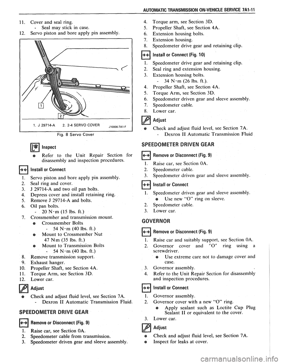
1 1. J 29714-A 2 2-4 SERVO COVER I
Fig. 8 Servo Cover
Inspect
e Refer to the Unit Repair Section for
disassembly and inspection procedures.
lnstall or Connect
Servo piston and bore apply pin assembly.
Seal ring and cover.
J 29714-A and two oil pan bolts.
Depress cover and install retaining ring.
Remove
J 29914-A and bolts.
Oil pan bolts.
- 20 N-m (15 lbs. ft.)
Crossmember and transmission mount.
Crossmember Bolts
- 54 N-m (40 Ibs. ft.)
e Mount to Crossmember Nut
47 Nm (35
Ibs. ft.)
e Mount to Transmission Bolts
- 54 N-m (40 lbs. ft.)
Remove transmission support.
Exhaust hanger.
Propeller Shaft, see Section 4A.
Torque Arm, see Section 3D.
Lower car.
Adjust
a Check and adjust fluid level, see Section 7A.
- Dexron I1 Automatic Transmission Fluid.
SPEEDOMETER DRIVE GEAR
Remove or Disconnect (Fig. 9)
1. Raise car, see Section OA.
2. Speedometer cable from transmission.
3. Speedometer driven gear and sleeve assembly. 4.
Torque arm, see Section 3D.
5. Propeller Shaft, see Section
4A.
6. Extension housing bolts.
7. Extension housing.
8. Speedometer drive gear and retaining clip.
Install or Connect (Fig. 10)
1.
Speedometer drive gear and retaining clip.
2. Seal
ring and extension housing.
3. Extension housing bolts.
- 34 N.m (26 Ibs. ft.).
4. Propeller Shaft, see Section 4A.
5. Torque Arm, see Section 3D.
6. Speedometer driven gear and sleeve assembly.
7. Speedometer cable.
8. Lower car.
a Adjust
e Check and adjust fluid level, see Section 7A.
- Dexron I1 Automatic Transmission Fluid
SPEEDOMETER DRIVEN GEAR
Remove or Disconnect (Fig. 9)
1. Raise car, see Section OA.
2. Speedometer cable.
3. Speedometer
driven gear and sleeve assembly.
Install or Connect
1. Speedometer driven gear and sleeve assembly.
a Use new "0" ring on sleeve.
2. Speedometer cable.
3. Lower car.
GOVERNOR
Remove or Disconnect (Fig. 9)
1. Raise car and suitably support, see Section OA.
2. Governor cover and "0" ring using
a
screwdriver.
e Use extreme care not to damage cover and
case.
3. Governor assembly.
4. Refer to the Unit Repair Section for disassembly
and inspection procedures.
Install or Connect
1. Governor assembly.
2. Governor
cover with a new
"0" ring.
e Apply sealant such as Loctite Cup Plug
Sealant
I1 or equivalent to the cover.
3. Lower car.
Adjust
e Check and adjust fluid level, see Section 7A.
e Inspect for leaks at cover.
Page 1131 of 1825
7A1-12 AUTOMATIC TRANSMISSION ON-VEHICLE SERVICE
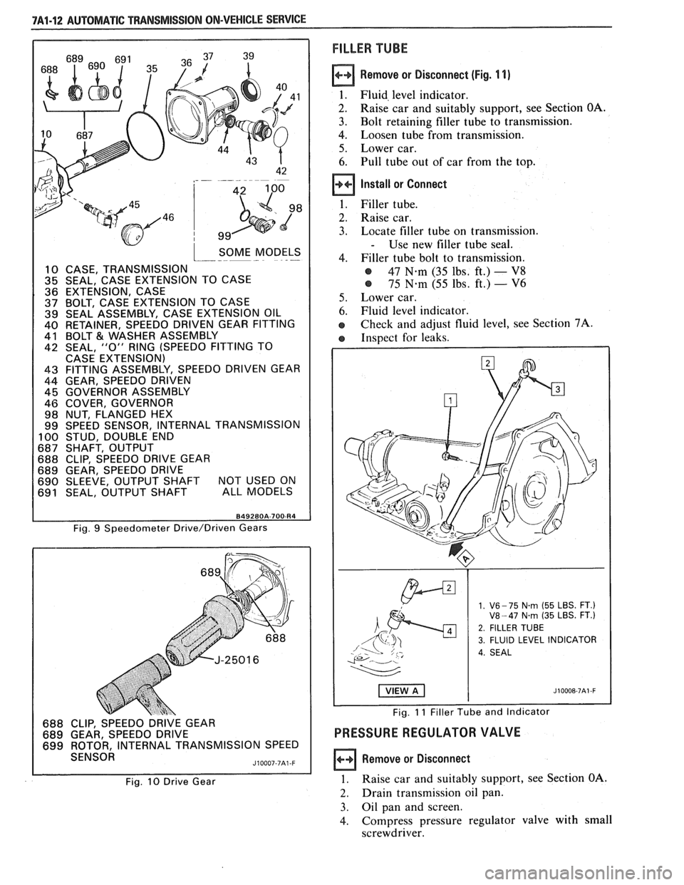
SOME MODELS I--- - .-
10 CASE, TRANSMISSION 35 SEAL, CASE EXTENSION TO CASE
36 EXTENSION, CASE 37 BOLT, CASE EXTENSION TO CASE 39 SEAL ASSEMBLY, CASE EXTENSION OIL 40 RETAINER, SPEEDO DRIVEN GEAR FITTING
41 BOLT €31 WASHER ASSEMBLY 42 SEAL, "0" RING (SPEEDO FITTING TO
CASE EXTENSION)
43 FITTING ASSEMBLY, SPEEDO DRIVEN GEAR
44 GEAR, SPEEDO DRIVEN 45 GOVERNOR ASSEMBLY
46 COVER, GOVERNOR
98 NUT, FLANGED HEX
99 SPEED SENSOR, INTERNAL TRANSMISSION
100 STUD, DOUBLE END 687 SHAFT, OUTPUT 688 CLIP, SPEEDO DRIVE GEAR
689 GEAR, SPEEDO DRIVE
690 SLEEVE, OUTPUT SHAFT NOT USED ON 691 SEAL, OUTPUT SHAFT ALL MODELS
FILLER TUBE
Remove or Disconnect (Fig. 1 1)
1. Fluid, level indicator.
2. Raise car and suitably support, see Section OA.
3. Bolt retaining filler tube to transmission.
4. Loosen tube from transmission.
5. Lower car.
6. Pull tube out of car from the top.
Install or Connect
1. Filler tube.
2. Raise car.
3. Locate filler tube on transmission.
- Use new filler tube seal.
4. Filler tube bolt to transmission.
@ 47 N.m (35 lbs, ft.) - V8
@ 75 N-m (55 lbs. ft.) - V6
5. Lower car.
6. Fluid level indicator.
e Check and adjust fluid level, see Section 7A.
e Inspect for leaks.
Fig. 9 Speedometer Drive/Driven Gears
688 CLIP, SPEEDO DRIVE GEAR
689 GEAR, SPEEDO DRIVE
699 ROTOR, INTERNAL TRANSMISSION SPEED
SENSOR
J10007-7A1 -F
Fig. 10 Drive Gear
1. V6- 75 N.rn (55 LBS. FT.) V8-47 N.rn (35 LBS. FT.)
2. FILLER TUBE
3. FLUID LEVEL INDICATOR
4. SEAL
Fig. 11 Filler Tube and Indicator
PRESSURE REGULATOR VALVE
Remove or Disconnect
1. Raise car and suitably support, see Section OA.
2. Drain transmission oil pan.
3. Oil pan and screen.
4. Compress
pressure regulator valve with small
screwdriver.
Page 1132 of 1825
AUTOMATIC TRANSMISSION ON-VEHICLE SERVICE 7A1-13
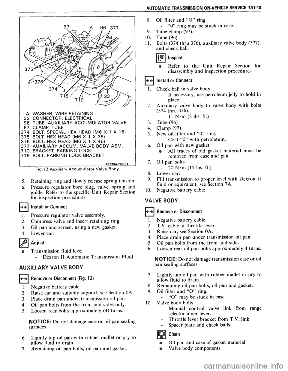
A WASHER, WIRE RETAINING
33 CONNECTOR, ELECTRICAL
96 TUBE, AUXILIARY ACCUMULATOR VALVE
97 CLAMP, TUBE
374 BOLT, SPECIAL HEX HEAD (M6
X 1 X 161
375 BOLT, HEX HEAD lM6
X 1 X 35)
376 BOLT, HEX HEAD lM6 X 1 X 45) , 377 AUXILIARY ACCUM. VALVE BODY ASM. 710 BRACKET, PARKING LOCK
71 5 BOLT, PARKING LOCK BRACKET
Fig. I2 Auxiliary Accumulator Valve Body
5. Retaining ring and slowly release spring tension.
6. Pressure regulator bore plug, valve, spring and
guide. Refer to the specific Unit Repair Section
for inspection procedures.
Install or Connect
1. Pressure regulator valve assembly.
2. Compress valve and insert retaining ring.
3. Oil pan
and screen, using a new gasket.
4. Lower car.
Adjust
cs Transmission fluid level.
- Dexron I1 Automatic Transmission Fluid
AUXILLARY VALVE BODY
Remove or Disconnect (Fig. 12)
I. Negative battery cable
2. Raise car and suitably support, see Section OA.
3. Place drain
pan under transmission oil pan.
4. Oil pan bolts from the front and sides only.
5. Loosen rear bolts approximately (4) turns.
NOTICE: Do not damage case or oil pan sealing
surfaces.
6. Lightly tap oil pan with rubber mallet or pry to
allow fluid to drain.
7. Remaining oil pan bolts, oil pan and gasket.
8. Oil filter and "0" ring.
- "0" ring may be stuck in case.
9. Tube clamp (97).
10. Tube (96).
11. Bolts (374 thru
376), auxiliary valve body (377),
and check ball.
Inspect
e Refer to the Unit Repair Section for
disassembly and inspection procedures.
Install or Connect
Check ball in valve body.
- If necessary, use petroleum jelly to hold in
place.
Auxiliary valve body to valve body with bolts
(374 thru 376).
- 11 N-rn(8lbs.ft.)
Tube (96)
Clamp (97)
New oil filter and "OW-ring.
- Coat "0" with petrolatum.
Oil pan with new gasket.
All traces of old gasket material must be
removed from case and pan.
Oil pan bolts.
- 20 Nem (15 Ibs. ft.)
Lower car.
Fill transmission to proper level with Dexron
I1
fluid or equivalent, see Section 7A.
Negative battery cable
VALVE BODY
Remove or Disconnect
1. Negative battery cable.
2. T.V. cable at throttle lever.
3. Raise car, see Section OA.
4. Place
drain pan under transmission oil pan.
5. Oil pan bolts from the front and sides.
6. Loosen
rear oil pan bolts approximately 4 turns.
NOTICE: Do not damage transmission case or oil
pan sealing surfaces.
7. Lightly
tap oil pan with rubber mallet or pry to
allow fluid to drain.
8. Remaining oil pan bolts, oil pan and gasket.
9. Oil
filter and
"0" ring.
- "0" may be stuck in case.
10. Valve body bolts.
- Manual control valve link from range
selector inner lever.
- Throttle lever bracket from T.V. link.
- Spacer plate and check balls.
Oil pan and case of gasket material.
e Valve body components.
Page 1133 of 1825
7A1-44 AUTOMATIC TRANSMISSION ON-VEHICLE SERVICE
Inspect
e Refer to the Unit Repair Section for
disassembly and inspection procedures.
Install or Connect
1. Valve body, spacer, check balls and bolts as
outlined in the Unit Repair Section.
2. New
"0" ring
seal and oil filter.
- Coat "0" ring seal with petrolatum.
3. New gasket, oil pan and bolts.
- 20 N.m (15 lbs. ft.)
4. Lower car.
5. Fill
transmission to proper level with Dexron
I1
fluid or equivalent, see Section 7A.
Adjust
e T.V. cable, see Figs. 5 thru 7.
REAR OIL SEAL
Remove or Disconnect
Tool Required:
J 21426 Seal Installer
1. Raise car and suitably support, see Section OA.
2. Propeller shaft, see Section 4A.
3. Pry out lip seal with a suitable tool.
Install or Connect
I. Coat outer casing of new lip oil seal with
non-hardening sealer and tap in place with
J
2 1426.
2. Propeller
shaft, see Section 4A.
3. Lower car.
Adjust
e Transmission fluid level.
- Dexron 11 Automatic Transmission Fluid
OIL COOLER LINES AND/OR FITTINGS
Figs. 13 and 14
If replacement of transmission cooler lines is
required, use only double wrapped and brazed steel
tubing meeting
GM specification 123M or equivalent.
Tubing should be double flared.
NOTICE: Allow sufficient clearance around
cooler lines to prevent damage or wear which may
cause fluid loss.
OIL COOLER FLUSHING
Tools Required:
J 35944 Cooler Flushing Tool
J 35944-20 Flushing Solution
Water Supply
Air Supply (with water and oil fil-
ter)
Oil Drain Container
5 Gallon Pail
1. Remove the fill cap on J 35944 and fill with .6
liters (20-21 ounces) of J 35944-20 flushing
solution.
@ Do not over fill
@ Follow manufacture's suggested proce-
dures for solution handling.
Replace cap on
J 35944 and pressurize it to 550-
700
kPa (80-100 psi).
Connect
J 35944 to the transaxle end of the oil
cooler pipe that feeds the BOTTOM fitting of
the oil cooler.
Connect the discharge hose to the TOP oil
cooler pipe and clip the discharge hose to the oil
drain container.
With the water valve on
J 35944 in the "off'
position, connect the water supply to the tool.
Turn the water valve off.
Flush the transaxle fluid by opening the water
valve to the "on" position for about 10 seconds.
Important
@ If water does not flow thru the cooler the
system is completely plugged. Do not
complete the flushing procedure. Replace
the cooler
and/or the cooler pipes as
required.
8. Close the water valve and clip the discharge
hose to the 5 gallon pail. Cover the pail with a
shop towel to prevent splash.
9. Turn the water valve to
the
"on" positon and
depress the trigger to mix flushing solution into
the water flow. Use the bail clip provided to
hold the trigger down.
10. Flush the
cooler with water and solution for 2
minutes. During this flush, attach the air supply
to the air valve located on the tool, for 3 to 5
seconds every 15-20 seconds. This will create a
surging action to ensure complete cleaning.
11. Release the trigger and turn the water valve off.
12. Disconnect both hoses from the oil cooler pipes.
13. Reconnect the hoses to the pipes opposite the
initial flush to preform a backflush.
14. Repeat steps 9 and 10
15. Release the trigger and allow water to rinse
for
one minute.
16. Turn the water valve off.
17. Attatch the air supply to the air valve and dry the
system out with air until no moisture is seen
leaving the discharge hose.
18. Connect the Cooler Feed Pipe to the transaxle.
19. Clip the discharge hose to the oil drain con-
tainer.
20. After filling the transaxle with
fluid,
start the
engine and run for 30 seconds. This will remove
any residual
moistrue from the oil cooler. A
minimum of 2 quarts of fluid should flow during
the 30 second period. If fluid flow is sufficient,
check the fluid flow by disconnecting the feed
Page 1136 of 1825
AUTOMATIC TFIANSMISSION ON-VEHICLE SERVICE 7A1-17
Fluid Capacity
@ Pi111 Kcmoval .................. 10 pinls (4.7 1,ilres)
@ Ovcrliaul ..................... 13 pints ( l0.0 I,irrcs)
Recommended Fluid
Dcxroli I1 Auronii~tic 11.ansniission I-'luitl # 105 1x55
@ Shift control cable.
T.V. cable
@ Fluid level
- Dexron I1 Automatic Transmission Fluid
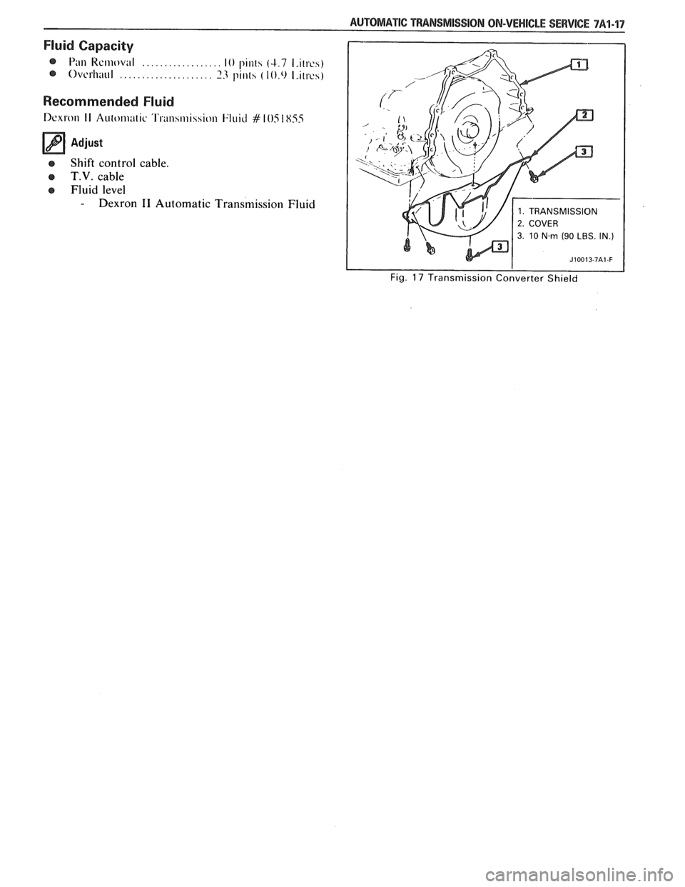
Fig. 17 Transmission Converter Shield
Page 1138 of 1825
SECTION 7B
5-SPEED 77MM TRANSM
RPO-M39 MK6 AND MBI
CONTENTS
........................... ................... ............................... General Description 7B-1 Gears ... 7B-12 .......................... .............................................. Diagnosis 7B-2 Front and Rear Bearings ..7B-12 ...................... ................................ On Vehicle Service 7B-3 Synchronizer Blocking Rings .7B-12 .................................................. ........................................... Shift Lever 7B-3 Repairs ,7B-12
......................................... ................... Transmission 7B-3 Synchronizer Keys and Springs .7B- 12
....................... ............... Extension Housing Oil Seal 7B-3 Extension
Oil Seal and/or Bushing .7B-13
Speedometer Driven Gear ......................... 7B-6
Drive Gear Bearing Retainer Oil Seal ............ 7B-14
........................................... .................................. Unit Repair 7B-6 Transmission Cover .7B-14
....................... ....................... Disassembly of Transmission 7B-6 Front Counter Shaft Bearing .7B-15 .............................. ......................... Disassembly of Mainshaft .7B- 10 Assembly of Drive Gear .7B- 16 ............................... ........................ Disassembly of Drive Gear ,7B- 1 1 Assembly of Mainshaft 7B- 16 ............................. ............................ Cleaning and Inspection ,7B-11 Assembly of Transmission 7B-17 ........................................ ............................... Transmission Case .7B-11 Specifications .7B-19
....................... .......... .................... Bearing Rollers and Spacers .7B-11 Special Tools ... .7B-20
GENERAL DESCRIPTION
Manual transmissions are identified by (A) the
number of forward gears and
(B) the measured dis-
tance between centerlines of the mainshaft and the
countergear.
The 5-speed 77mm transmission is a fully syn-
chronized unit with blocker ring synchronizers and a
sliding mesh reverse gear. First and second gears have
three-piece synchronizer rings, consisting of steel
inner and outer cones and
a tapered metal ring that is
lined on both sides with friction material similar to
automatic transmission friction plates. The cones are
independent of the gears and can be replaced sepa-
rately. Third and fourth gear blocker rings are more
conventional in appearance, but are also lined with
friction material. The fifth gear blocker ring is brass.
NOTICE: No lubricant other than Dexron I1
#I051855 or equivalent should be used in this
transmission. Other lubricants or additives may
damage the blocker ring friction material or its
adhesive.
The mainshaft and the countershaft are sup-
ported on tapered roller bearings and must be
shimmed for proper end play. First through fourth
speed mainshaft gears ride on caged roller bearings.
An aluminum transmission case houses the various gears and bearings. The gearshift lever assembly is
floor-mounted and is located on top of the extension
housing. The shift mechanism does not require adjust-
ment and can be serviced independently of the
transmission.
Page 1297 of 1825
STARTER AND CHARGING SYSTEM
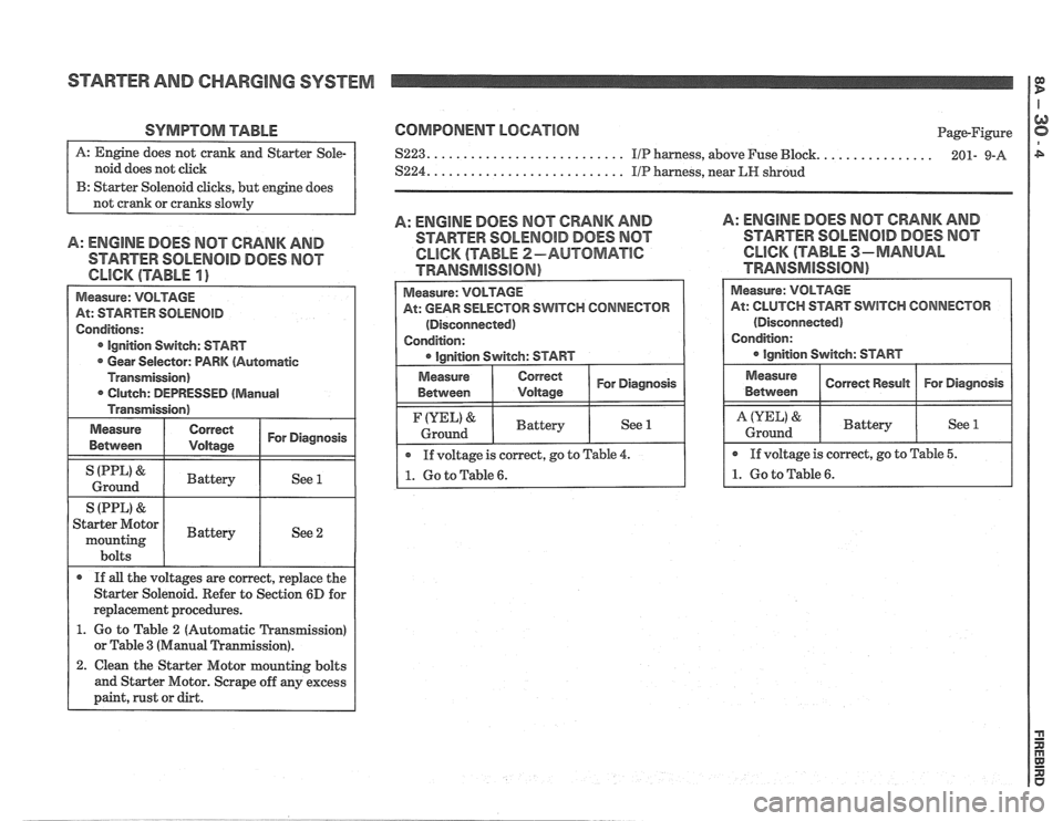
SYMPTOM TABLE
noid does not click
B: Starter Solenoid clicks, but engine does
A: ENGINE DOES MOT CRANK AND
STARTER SOLENOID DOES NOT
Measure: VOLTAGE
At: STARTER
SOLENOID
Conditions:
Ignition Switch: START
Gear Selector: PARK (Automatic
Transmission) Clutch: DEPRESSED
(Manual
Transmission)
Measure
Between
Correct I For Diagnosis I
I (PPL' & I Battery I See 1 I Ground
S (PPL)
& I I
Starter Motor
mounting I Battery I See 2
bolts
If
all the voltages are correct, replace the
Starter Solenoid. Refer to Section
6D for
replacement procedures.
1. Go to Table 2 (Automatic Transmission)
or Table
3 (Manual Tranmission).
2. Clean the Starter Motor mounting bolts
and Starter Motor. Scrape off any excess
paint, rust or dirt.
COMPONENT LOCATION
....... $223. .......................... IIP harness, above Fuse Bbck.
S224. .......................... IIP harness, near LIP shroud Page-Figure
........ 201- 9-A
A: ENGINE DOES MOT CRANK AND
STARTER SOLENOID DOES NOT
CLICK (TABLE 2-AUTOMATlC
TRANSMISSION)
A: ENGINE DOES MOT CRANK AND
STARTER SOLENOID DOES MOT
CLICK (TABLE 3-MANUAL
TRAMSMiSS16N)
Measure:
VOLTAGE
At: GEAR SELECTOR SWITCH CONNECTOR
(Disconnected)
Condition:
Correct 1 For Diagnosis I
If voltage is correct, go to Table 4.
1. Go to Table 6.
(YEL) &
Ground
At: CLUTCH START SWITCH CONNECTOR
(Disconnected)
Battery See 1
Page 1298 of 1825
STARTER AND CHARGING SYSTEM
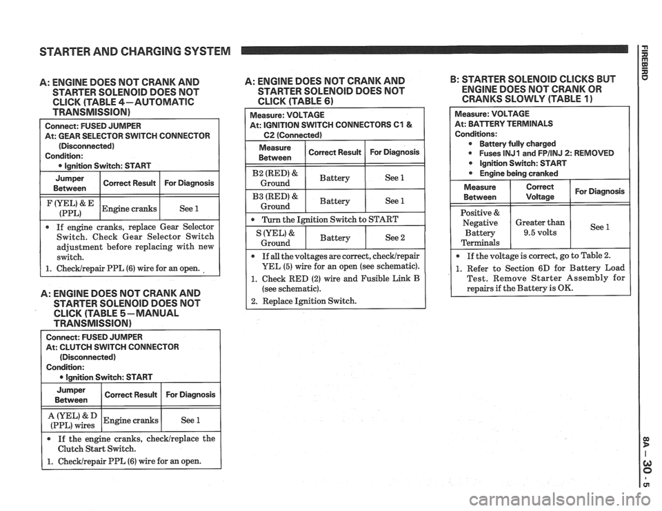
A: ENGINE DOES NOT CRANK AND
STARTER SOLENOID DOES NOT
CLICK (TABLE 4-AUTOMATIC
TRANSMISSION)
Connect: FUSED JUMPER
At: GEAR SELECTOR SWITCH CONNECTOR
(Disconnected)
Condition:
0 Ignition Switch: START
I
Jumper I Corren Resuk I For Diagnosis I Between
I (:::LI& IEngine cranks I See 1 1
If engine cranks, replace Gear Selector
Switch. Check Gear Selector Switch
adjustment before replacing with new
switch.
1. ChecWrepair PPL (6) wire for an open.
A: ENGINE DOES NOT CRANK AND
STARTER SOLENOlD DOES NOT
CLICK (TABLE 5-MANUAL
TRANSMISSION)
Connect: FUSED JUMPER
At: CLUTCH SWITCH CONNECTOR
(Disconnected)
Condition:
I 0 lanition Switch: START I
I :if,",":: 1 Engine cranks I See 1 I
Jumper
Between
If the engine cranks, checklreplace the
Clutch Start Switch.
1. Checklrepair PPL (6) wire for an open.
A: ENGINE DOES NOT CRANK AND B:
STARTER SOLENOID CLICKS BUT
STARTER
SOLENOID DOES NOT ENGINE DOES NOT CRANK OR
CLICK (TABLE 61 CRANKS SLOWLY (TABLE 1)
Correct Result Measure:
VOLTAGE
At: IGNITION SWITCH CONNECTORS
C1 &
C2 (Connected)
For Diagnosis
I Measure ( Correct Result I For Diagnosis 1 Between
I B2 (RED)& I Battery ( See 1 I Ground
I B3 IRED'& I Battery ( See 1 1 Ground
0 Turn the Ignition Switch to START
Measure: VOLTAGE
At: BPirTERV TERMINALS
Conditions: Battery fully charged
0 Fuses lNJ1 and FPIINJ 2: REMOVED
Ignition Switch: START
Engine being cranked
See 2 IYEL' &
Ground
For Diagnosis
See
Measure
Between
Positive &
Negative Battery
Terminals
If
all the voltages are correct, checklrepair
YEL (5) wire for an open (see schematic).
1. Check RED (2) wire and Fusible Link B
(see schematic).
2. Replace Ignition Switch.
Battery
0 If
the voltage is correct, go to Table 2.
1. Refer to Section 6D for Battery Load
Test. Remove Starter Assembly for
repairs if the Battery is
OK.
Correct
Voltage
Greater than
9.5 volts