1988 PONTIAC FIERO automatic transmission
[x] Cancel search: automatic transmissionPage 1299 of 1825
STARTER AND CHARGING SYSTEM
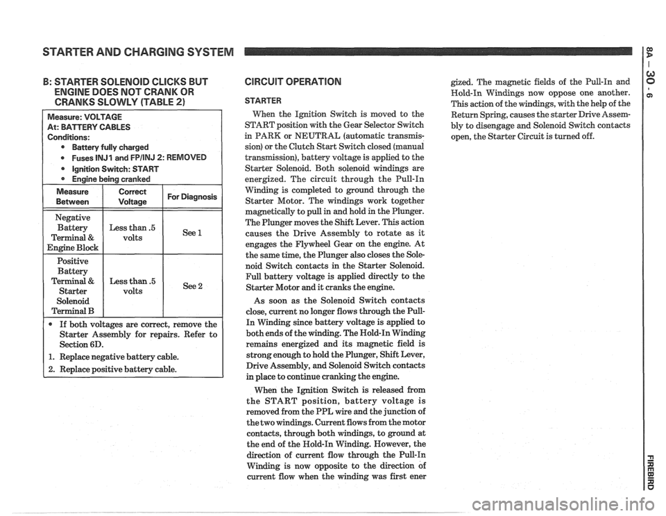
: STARTER SOLENOID CLICKS BUT
ENGINE DOES NOT CRANK OR
CRANKS SLOWLY (TABLE
2)
Battery fully charged
Fuses
lNJl and FPIINJ 2: REMOVED
Starter Assembly for repairs. Refer to
1. Replace negative battery cable.
2. Replace positive battery cable.
CIRCUIT OPERATION
STARTER
Wen the Ignition Switch is moved to the
START position with the Gear Selector Switch
in PARK or NEUTRAL (automatic
transrnis-
sion) or the Clutch Start Switch closed (manual
transmission), battery voltage is applied to the
Starter Solenoid. Both solenoid windings are
energized. The circuit through the Pull-In
Winding is completed to ground through the
Starter Motor. The windings work together
magnetically to pull in and hold in the Plunger.
The Plunger moves the Shift Lever. This action
causes the Drive Assembly to rotate as
it
engages the Flywheel Gear on the engine. At
the same time, the Plunger also closes the Sole-
noid Switch contacts in the Starter Solenoid.
Full battery voltage is applied directly to the
Starter Motor and it cranks the engine.
As soon as the Solenoid Switch contacts
close, current no longer flows through the Pull-
In Winding since battery voltage is applied to
both ends of the winding. The Nold-In Winding
remains energized and its magnetic field is
strong enough to hold the Plunger, Shift Lever,
Drive Assembly, and Solenoid Switch contacts
in place to continue cranking the engine.
When the Ignition Switch is released from
the START position, battery voltage is
removed from the PPL wire and the junction of
the two windings. Current flows from the motor
contacts, through both windings, to ground at
the end of the Hold-In Winding. However, the
direction of current flow through the Pull-In
Winding is now opposite to the direction of
current flow when the winding was first ener
gized. The magnetic fields of the Pull-In and
Hold-In Windings now oppose one another.
This action of the windings, with the help of the
Return Spring, causes the starter Drive Assem-
bly to disengage and Solenoid Switch contacts
open, the Starter Circuit is turned off.
Page 1489 of 1825
BACK UP LIGHTS
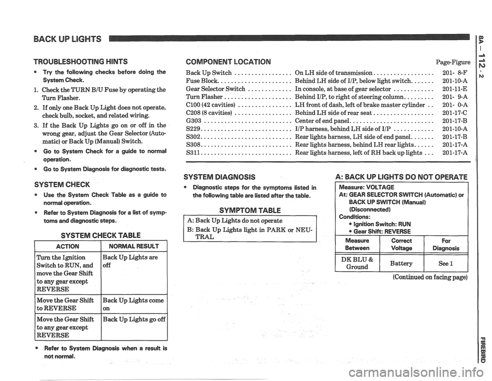
TROlJBLESHQOTlNG HINTS COMPONENT LOCATION Page-Figure
Try the following checks before doing the Back Up Switch ................. On LN side of transmission. ................. 201- 8-F
System Check. Fuse Block. ..................... Behind LH side of IIP, below light switch. ...... 201-10-A
............. ............ 1. Check the TURN BIU Fuse by operating the Gear
Selector Switch In
console, at base of gear selector
201-11-E
.................... Flasher. Flasher Behind IIP, to right of steering column. ........ 201- 9-A
2. If only one Back Up Light does not operate,
check bulb, socket,
and related
3. If the Back Up Lights go on or off in the
mong gear, adjust the Gear Selector (Auto-
matic) or Back Up (Manual) Switch.
el00 (42 cavities) ................ LR front of dash, left of brake master cylinder ..
C208 (8 cavities) ................. Behind LH side of rear seat. .................
6303 .......................... Center of end panel. ........................
S229. .......................... IIP harness, behind LH side of IIP ............
S302. .......................... Rear lights harness, LH side of end panel. ......
S308. .......................... Rear lights harness, behind LH rear lights. ..... - - Go to System Check for a guide to normal S3 11. .......................... Rear lights harness, left of RN back up lights
201-17-A ...
operation.
Go to System Diagnosis for diagnostic tests.
SYSTEM DlAGRlOSlS A: BACK UP LlGHTS DO NOT OPERATE
SYSTEM CHECK
Diagnostic steps for the symptoms listed in
Use the System Check Table as a guide to
the following table are listed
aMer the table. WlTCH (Automatic) or
normal operation. BACK
UP SWITCH
(Manual)
Refer to System Diagnosis for
a list of symp-
toms and diagnostic steps.
SYSTEM CHECK TABLE
the Ignition
Switch to RUN, and
move the Gear Shift
to
any gear except
REVERSE
Move the Gear Shift Back Up Lights come
to REVERSE 1 on - -
Move the Gear Shift Back
Up Lights go off
to any gear except
REVERSE
Refer to System Diagnosis when a result is
SYMPTOM TABLE
A: Back Up Lights do not operate
B: Back Up Lights light in PARK or NEU-
TRAL
(Continued on facing page)
not normal. Between
I Voltage I Diagnosis
I DKBLU& I Battery I See l I Ground
Page 1490 of 1825
BACK UP LIGHTS
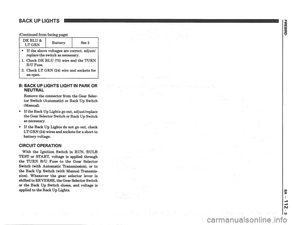
1. Check DK BLU (75) wire and the TURN
B: BACK UP LlGHTS LIGHT IN PARK OR
NEUTRAL
Remove the connector from the Gear Selec-
tor Switch (Automatic) or Back Up Switch
(Manual).
If the Back Up Lights go out, adjustlreplace
the Gear Selector Switch or Back Up Switch
as necessary.
If the Back Up Lights do not go out, check
LT GRN
(24) wires and sockets for a short to
battery voltage.
CIRCUIT OPERATION
With the Ignition Switch in RUN, BULB
TEST or START, voltage is applied through
the TURN
BIU Fuse to the Gear Selector
Switch (with Automatic Transmission), or to
the Back Up Switch (with Manual Transmis-
sion). Whenever the gear selector lever is
s&&ed to REVERSE, the Gear Selector Switch
or the Back Up Switch closes, and voltage is
applied to the Back Up Lights.
Page 1530 of 1825
AUTOMATIC DAY-NIGHT MIRROR
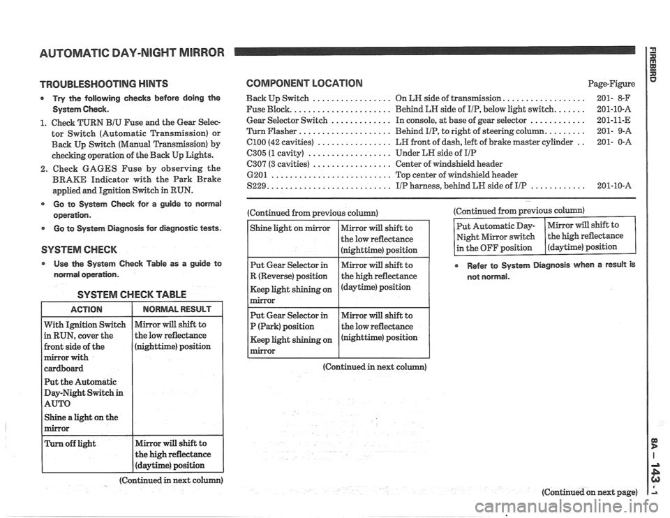
TROUBLESHOOTING MINTS
Try the following checks before doing the
System
Gheck.
1. Check TURN BIU Fuse and the Gear Selec-
tor Switch (Automatic Transmission) or
Back
Up Switch (Manual 'L'ransfission) by
checking operation of the Back Up Lights.
2. Check GAGES Fuse by observing the
BRAKE Indicator with the Park Brake
applied and
IMtion Switch in RUN.
@ Go to System Gheck for a guide to normal
operation.
Go to System Diagnosis for diagnostic tests.
Use the System Check Table as a guide to
normal operation.
SYSTEM CHECK TABLE
nighttime) position
t the Automatic
ay-Night Switch
in
Shine a light on the
COMPONENT LOCATION Page-Figure
.................. Back Up Switch ................. On LN side of transIlnission 201- 8-F
...... Fuse Block. ..................... Behind LN side of IIP, below light switch. 201-10-A
............ Gear
Selector Switch ............. In console, at base of gear selector 201-11-E
........ 'Turn Flasher .................... Behind
PIP, to right of steering column. 201-
9-A
.. C100 (42 cavities) ................ LR front of dash, left of brake master cylinder 201-
0-A
6305 (1 cavity) .................. Under LH side of IIP
C307 (3 cavities) ................. Center of windshield header
6201
.......................... Top center of windshield header
............ S229. .......................... IIP harness, behind LW side of IIP 201-10-A
(Continued from previous column)
(Continued in next co (Continued
from previous column)
Refer to System Diagnosis when a result is
not normal.
(Continued in next colum)
(Continued on next page)
Page 1569 of 1825
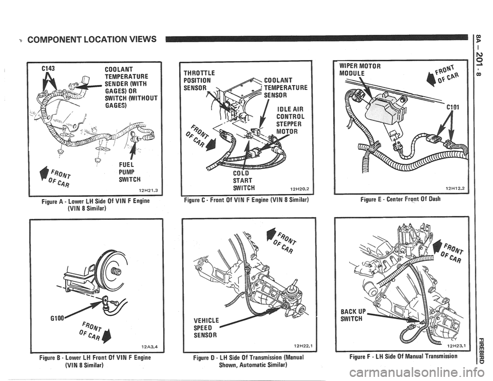
COMPONENT LOCATION VIEWS I $
6143 COOLANT
TEMPERATURE
SENDER (WITH
GAGES) OR
SWITCH (WITHOUT
GAGES)
FUEL
1) F~oer PUMP
OF c.4 Fj SWITCH
12H21.3
Figure A - Lower LH Side Of VIN F Engine
(VIN 8 Similar)
Figure
B - Lower LH Front Of VIN F Engine
(VIN 8 Similar) THROTTLE
POSITION
START
WITCH 12H20.2
Figure C - Front Of VIN F Engine (VIM 8 Similar)
SENSOR
12H22.1
Figure D - LH Side Of Transmission (Manual
Shown, Automatic Similar) Figure
E
- Center Frcpt Of Dash
Figure
F - LN Side Of Manual Transmission
Page 1600 of 1825
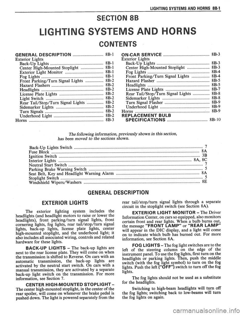
LIGHTING SYSTEMS AND HORNS 8B-I
SECTION 8B
NG SYSTEMS AND HORNS
CONTENTS
........................... GENERAL DESCRIPTION 8B-1
Exterior Lights
....................... ................... Back-up Lights .. 8B- 1
Center High-Mounted Stoplight .................... 8B-1
Exterior Light Monitor .................................. 8B-1
............................ .................... Fog Lights .. 8B-1
Front Parking/Turn Signal Lights ................ 8B-2
............................... Hazard Flashers .. ........ 8B-2 .................................................... Headlights 8B-2
License Plate Lights ..................................... 8B-2
Light Switch ............................................... 8B-2
............... Rear Tail/Stop/Turn Signal Lights 8B-2
Sidemarker Lights ........................................ 8B-2
Turn Signals .......................................... 8B-2
......................... Underhood Light ... ........ 8B-2
Horns .......................................................... 8B-3
....................................... ON-CAR SERVICE 8B-3
Exterior Lights
............................................. Back-up Lights 8B-3
Center High-Mounted Stoplight .................... 8B-3
Fog Lights .................................................... 8B-4
Front Parking/Turn Signal Lights ................ 8B-4
Hazard Flasher .............................................. 8B-5
....................................................... Headlights 8B-5
License Plate Lights ..................................... 8B-7
............... Rear Tail/Stop/Turn Signal Lights 8B-8
.......................................... Sidemarker Lights 8B-8
................... ............... Turn Signal Flasher .. 8B-9
......................................... Underhood Light 8B-9
Horns ................................................................. 8B-9
REPLACEMENT BULB
.................................... SPECIFICATIONS 8B- 10
The following information, previously shown in this section,
has been moved to the sections shown.
Back-up Lights Switch
............................. ... ............................................................................ 7
................................................................................................................................. Fuse Block 8A
Ignition Switch ........................................................................................................................... 3B
Interior Lights
................................................................................................................... 8A, 8C
Neutral Start Switch ..................................................................................................................... 7
Parking Brake Warning Switch
......................... ... .................................................................... 5
........................................................................ Seat Belt, Key and Headlight Warning Alarm 8A
Stoplight Switch .......................... .. ............................................................................................... 5
Windshield
Wipers/Washers .................................................................................................... 8E
GENERAL DESCRIPTION
The exterior lighting system includes the
headlights (and headlight motors to raise or lower the
headlights), front
parkinghurn signal lights, front
cornering lights, fog lights, rear
tail/stop/turn signal
lights, back-up lights, license plate lights, center
high-mounted stoplight, and the underhood light; it
also includes all associated wiring, controls and related
hardware for these lights.
BACK-UP LIGHTS - The back-up lights are
next to the rear license plate. They will come on when
the transmission is shifted to Reverse. On cars with an
automatic transmission, the back-up lights are
activated by the neutral start switch. On cars with a
manual transmission, they are activated by a separate
back-up light switch on the transmission. For more
information, see Section 7.
CENTER HIGH-MOUNTED STOPLIGHT-
The center high-mounted stoplight, in the center of the
rear spoiler, will come on whenever the brake pedal is
pushed down. The light is powered separately from the rear
tail/stop/turn signal
lights through a separate
circuit in the stoplight switch (see Section
8A).
EXTERIOR LIGHT MONITOR - The Driver
Information Center, on cars so equipped, also monitors
certain front and rear lights. When a bulb burns out,
the message
"FRONT LAMP" or "REAR LAMP"
will appear in the DIC display, and a light will come
on to indicate which bulb has burned out. For more
information, see Section
8A.
FOG LIGHTS -The fog light switches are to the
left of the steering column on the edge of the
instrument panel. To use the fog lights, first turn on the
headlights or parking lights. Then, push the middle
switch (with the fog light symbol) to turn on the fog
lights. Push the left
("OFF") switch to turn off the fog
lights.
The fog lights should not be used as a substitute
for the headlights.
Switching to high-beam headlights will turn off
the fog lights; switching back to low-beams will turn
the fog lights on again.
Page 1766 of 1825
ROOF - F STYLE 8H-7
SECTION A-A VIEW A
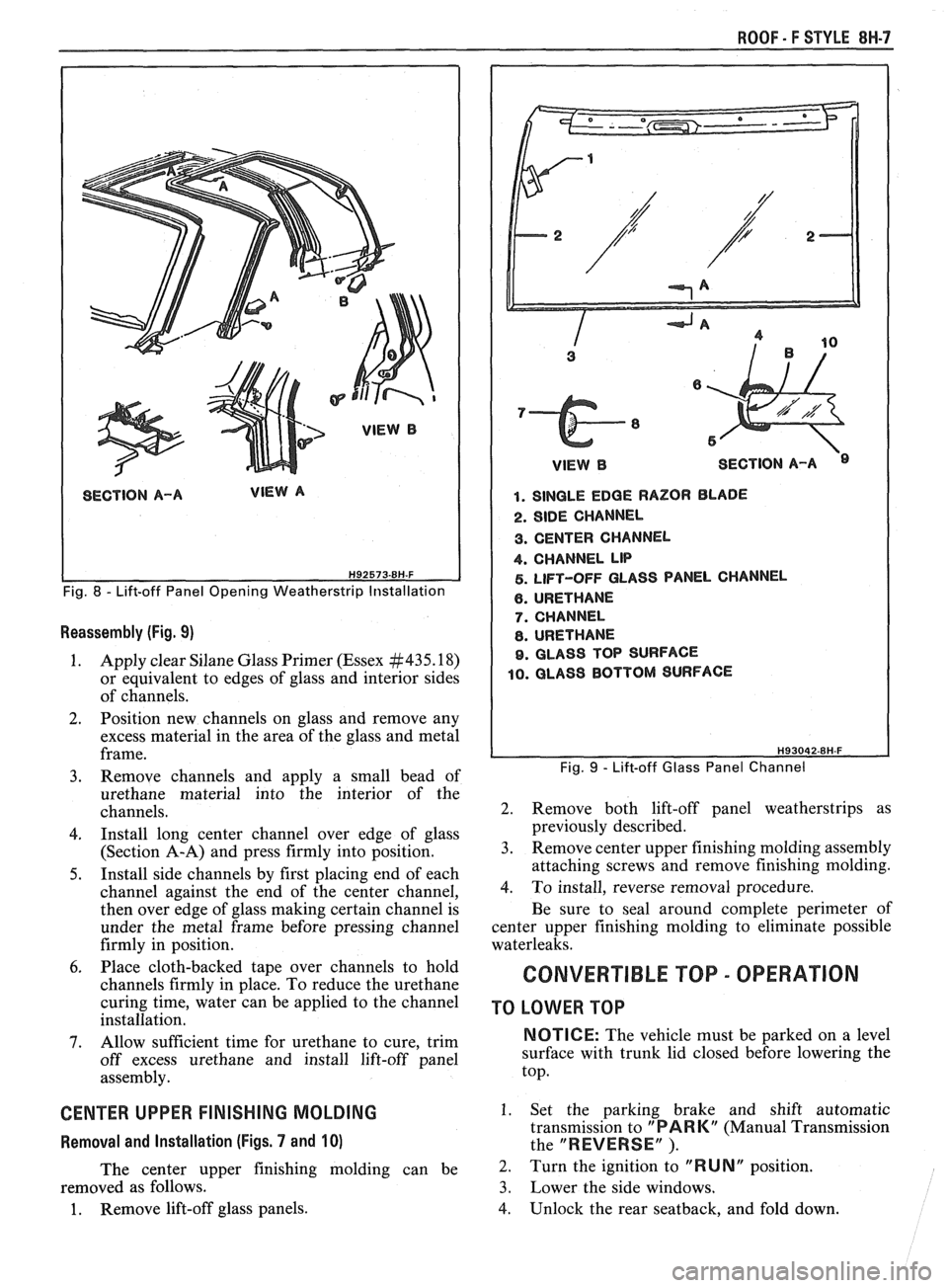
Fig. 8 - Lift-off Panel Opening Weatherstrip Installation
Reassembly (Fig. 9)
1. Apply clear Silane Glass Primer (Essex #435.18)
or equivalent to edges of glass and interior sides
of channels.
2. Position new channels on glass and remove any
excess material in the area of the glass and metal
frame.
3. Remove channels and apply a small bead of
urethane material into the interior of the
channels.
4. Install long center channel over edge of glass
(Section A-A) and press firmly into position.
5. Install side channels by first placing end of each
channel against the end of the center channel,
then over edge of glass making certain channel is
under the metal frame before pressing channel
firmly in position.
6. Place cloth-backed tape over channels to hold
channels firmly in place. To reduce the urethane
curing time, water can be applied to the channel
installation.
7. Allow sufficient time for urethane to cure, trim
off excess urethane and install lift-off panel
assembly.
CENTER UPPER FINISHING MOLDING
Removal and Installation (Figs. 7 and 10)
The center upper finishing molding can be
removed as follows.
1. Remove lift-off glass panels.
1 VlEWB SECTION A-A
1. SINGLE EDGE RAZOR BLADE
2. SIDE CHANNEL
3. CENTER CHANNEL
4. CHANNEL LIP
5. LIFT-OFF GLASS PANEL CHANNEL
6. URETHANE
7. CHANNEL
8. URETHANE
9. GLASS TOP SURFACE
10. GLASS BOTTOM SURFACE
Fig. 9 - Lift-off Glass Panel Channel
2. Remove both lift-off panel weatherstrips as
previously described.
3. Remove center upper finishing molding assembly
attaching screws and remove finishing molding.
4. To install, reverse removal procedure.
Be sure to seal around complete perimeter of
center upper finishing molding to eliminate possible
waterleaks.
CONVERTIBLE TOP - OPERATION
TO LOWER TOP
NOTICE: The vehicle must be parked on a level
surface with trunk lid closed before lowering the
top.
1. Set the parking brake and shift automatic
transmission to
"PARK" (Manual Transmission
the
"REVERSE" ).
2. Turn the ignition to "RUNN position.
3. Lower the side windows.
4. Unlock the rear seatback, and fold down.
Page 1767 of 1825
8H.8 ROOF - F STYLE
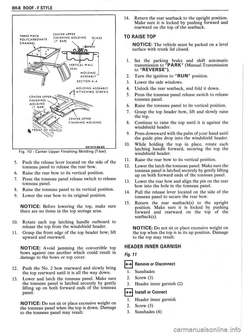
THREE PIECE CENTER
UPPER POLYCARBONATE FINISHING MOLDING GLASS (1 BAR)
CHANNEL 1
VERTICAL WALL
SECTION A-A
MOLDING ASSEMBLY
A ATTACHING SCREWS
Fig. 10 - Center Upper Finishing Molding (T-bar)
5. Push the release lever located on the side of the
tonneau panel to release the rear bow.
6. Raise the rear bow to its vertical position.
7. Press the tonneau panel release switch to release
tonneau panel.
8. Raise the tonneau panel to its vertical position.
9. Lower the rear bow to its original position.
NOTICE: Before lowering the top, make sure
there are no items in the top storage area.
10. Rotate
each top latching handle outboard to
release the top from the windshield header.
11. Grasp
the front edge of the top header bow; lift
upward and rearward.
N OTI C E: Avoid jamming the convertible top
bows against one another which could result in
damage to the bows or top cover.
12. Push the
No. 2 bow rearward and slowly bring
the top rearward until it is all the way down.
13. Lower
and latch the tonneau panel. Make sure
the tonneau panel is latched securely by gently
lifting up on both forward ends of the tonneau
panel.
NOTICE: Do not sit or place excessive weight on
the tonneau panel when the top is down. Damage
to the tonneau panel may result.
14. Return the rear seatback to the upright position.
Make sure it is locked by pushing forward and
rearward on the top of the seatback.
TO RAISE TOP
NOTICE: The vehicle must be parked on a level
surface with trunk lid closed.
1. Set the parking brake and shift automatic
transmission to
"PARK" (Manual Transmission
to
"REVERSE").
2. Turn the ignition to "RUN" position.
Lower the side windows.
Unlock the rear seatback, and fold it down.
Press the tonneau panel release switch to release
tonneau panel.
Raise the tonneau panel to its vertical position.
Grasp the top header bow, lift and slowly raise
the top.
Continue to raise the top until it is against the
windshield header.
Press downward with the palm of your hand until
the guide pins drop into the windshield header.
While holding the top in place, rotate each
latching handle forward, securing the top the
windshield header.
Raise the rear bow to its vertical position.
Lower the latch the tonneau panel. Make sure the
tonneau panel is latched securely by gently lifting
up on both forward ends of the tonneau panel.
Lower the rear bow and align the pin on the rear
bow into the hole in the tonneau panel.
Pull the release lever located on the side of the
tonneau panel to secure the rear bow.
Return the rear
seatback(s) to the upright
position. Make sure it is locked by pushing
forward and rearward on the top of the
seatback(s).
NOTICE: Do not sit or place excessive weight on
the top when the top is in its up position. Damage
to the top may result.
HEADER INNER GARNISH
Fig. 11
Remove or Disconnect
1. Sunshades
2. Screw (3)
3. Header inner garnish (2)
Install or Connect
1. Header inner garnish
2. Screw (3)
3. Sunshades
(4)