1988 PONTIAC FIERO automatic transmission
[x] Cancel search: automatic transmissionPage 627 of 1825
6Ef-C8-2 BRlVEABlLlYV AND EMISSIONS - 5.OL (VIN E) ----
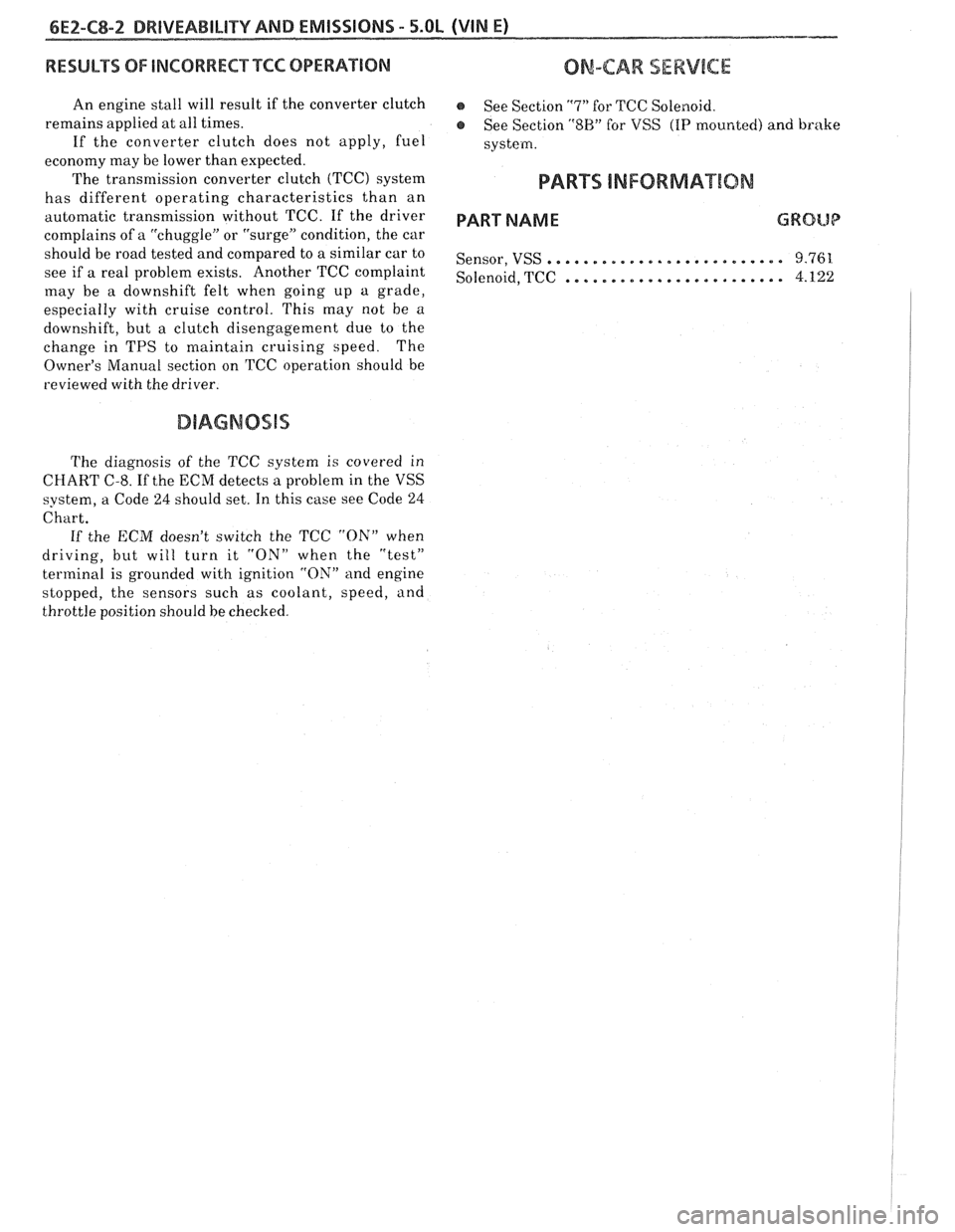
RESULTS OF INCORRECTTCC OPERATION
An engine stall will result if the converter clutch
remains applied at all times.
If the converter clutch does not apply, fuel
economy may be lower than expected.
The transmission converter clutch
(TCC) system
has different operating characteristics than an
automatic transmission without TCC.
If the driver
complains of a "chuggle" or "surge" condition, the car
should be road tested and compared to a similar car to
see if a real problem exists. Another TCC complaint
may be
a downshift felt when going up a grade,
especially with cruise control. This may not be
a
downshift, but a clutch disengagement due to the
change in TPS to maintain cruising speed. The
Owner's Manual section on TCC operation should be
reviewed with the driver.
DIAGNOSIS
The diagnosis of the TCC system is covered in
ClIART C-8. If the ECM detects a problem in the VSS
system, a Code
24 should set. In this case see Code 24
Chart.
If the ECM doesn't switch the TCC "ON" when
driving, but will turn it
"ON" when the "test"
terminal is grounded with ignition "ON" and engine
stopped, the sensors such as coolant, speed, and
throttle position should be checked.
ON-CAW SERVICE
@ See Section "7" for TCC Solenoid.
@ See Section "SH" for VSS (HP mounted) and brake
system.
PAR- SNFORMATBIQN
PART NAME GRQUQ
.......................... Sensor, VSS 9.761
........................ Solenoid, TCC 4.122
Page 629 of 1825

6EZ-C8-4 DRIVEABILITY AND EMISSIONS - 5.OL (VIN E)
I5 WAY (FRONT VIEW)
SPEED INPUT
4rH GEAR SIGNAL
422 TANIBLK
ALDL CONNECTOR
CHART C-8A
TRANSMISSION CONVERTER CLUTCH (TCC)
ELECTRICAL DIAGNOSIS
(Page 1 of 2)
5.OL (VIN E) "F" "SERIES (TBI)
Circuit Description:
The purpose of the automatic transmission torque converter clutch is to eliminate the power loss of the
torque converter, when the vehicle is in a cruise condition. This allows the convenience of the automatic
transmission and the fuel economy of a manual transmission.
Fused battery ignition is supplied to the TCC solenoid through the brake switch. the ECM will engage
TCC
by grounding CKT 422 to energize the solenoid.
TCC will engage when:
- Vehicle speed above 24 mph - Engine at normal operating temperature (above 70°C, 156°F)
- Throttle position sensor output not changing, indicating a steady road speed
- Brake switch closed
Test Description: Numbers below refer to circled solenoids
and relays before installing a
numbers on the diagnostic chart. replacement ECM. Replace
any solenoid or relay
1. Confirms 12 volt supply as well as continuity of that
measures less than 20 ohms.
TCC circuit.
2. Grounding the diagnostic terminal with engine Diagnostic Aids:
"OFF", should energize the capability of the ECM An
engine coolant thermostat that is stuck open or
to control the solenoid. opens
at too low a temperature, may result in an
3. Solenoid coil resistance must measure more than inoperative TCC.
20 ohms. Less resistance will cause early failure
of the ECM
drive^.". Using an ohmmeter, check
the solenoid coil resistance of
all ECM controlled
Page 642 of 1825
SECTION PAGE
A
Acceleration Mode .................... C2-2
AIC Request Signal
General Description
................. C1-4
Diagnosis ......................... C1-5
Air Injection Check Valve C6-3
Air Injection Control (Pedes) Valve
........ C6-3
Air
lnjection Reaction (A.I.R.) System
General Description
.................. C6- 1
Diagnosis ......................... C6-2
Part Information
.................... C6-4
Air Management Check (Pedes)
.......... C6-6
Air Pump
............................ C6-2
........................... Service C6-3
ALDL Connector ....................... A-1 2
Automatic Transmission Converter Clutch
(TCC) Electrical Diagnosis
.............. C8-4
C8-6
B
Backfire ............................ 6-6
......... Battery Voltage Correction Mode C2-2
Before
Start~ng ...................... B-1
C
Cal Pak General
Descript~on ................. C1-2
Service
........................... C1-8
Canister Control Valve
................. C3-2
Canister Hoses
....................... C3-3
Canister Purge Solenoid
................ C3-3
Canister Purge Valve Check
............. C3-6
Chart A-
I :
No Service Engine Soon Light .......... A-10
Chart A-2:
No ALDL Data. Or Won't Flash Code 12.
Or Service Engine Soon Light On Steady
. . A-1 2
Chart A-3:
Engine Cranks But Won't Run
.......... A-14
Chart A-7:
Fuel System Diagnosis
................ A-1 8
Chart
B-1:
Restricted Exhaust System Check ........ 6-7
Chart C-IA:
ParkINeutral Switch Diagnosis ......... Cl-12
Chart C-16:
Crank Signal
....................... C1-14
Chart C-1 D
.................. MAP Output Check C1-16
SECTION
Chart C-2C:
Idle Air Control (IAC) System Check ...... C2-18
Chart C-3:
Canister Purge Valve Check
........... C3-6
Chart C-4B:
Ignition System Check
................ C4-4
Chart C-5:
Electronic Spark Control
(ESC) .......... C5-4
Chart C-66:
Air Management Check
.............. C6-6
Chart C-7:
Exhaust Gas Recirculation
............. C7-4
Chart
C-$A:
Transmission Converter Clutch (TCC) .... C8-4
Chart
C-8A
700-4R Transmission Electrical Diagnosis . . C8-6
Chart
C-86:
Shift Light ......................... C8-8
Chuggle
............................ B-3
Clear Flood Mode
..................... C2-2
Closed Loop
......................... C2-2
Code12
............................ C4-2
Code13
............................ A-22
Code14
............................ A-24
Code43
............................ A-42
Code44
............................ A-44
Code45
............................ A-46
Code54
............................ A-48
Codes 5 1.52. 55
...................... A-50
Component Location
.................. A-2
Control Valves
....................... C3-3
Coolant Temperature Sensor
General Description
.................. C1-2
Diagnosis
.......................... Cl-5
Service
........................... C1-8
Cuts Out ............................ 6-4
Crank Signal General Description
................. C1-4
Diagnosis
......................... C1-14
D
Deceleration Mode .................... C2-2
Page 647 of 1825
FUNCTIONAL CHECKS/
DIAGNOSTIC CHARTS
2.8L (VIN S)
ECM QDR Check
......................... Chart C-1 C1-10
ParkINeutral Switch
......................... Chart C-1A C1-12
Power Steering Pressure Switch Check
........................ ChartC-1E C1-14
Injector Balance Test
........................ Chart C-2A C2-18
Idle Air Control
........................ Chart C-2C C2-20
Canister Purge Valve Check
......................... Chart C-3 C3-4
Ignition System Check
........................ Chart C-4A C4-4
Electr~c Control (Divert) -(Manual Transmission)
......................... Chart C-6 C6-6
Exhaust Gas Recirculation Check
........................ Chart C-7 C7-6
Automatic Transmission
Converter Clutch (TCC)
. (I of 2)
........................ Chart C-8 C8-2
Transmiss~on Converter Clutch
(TCC) Electrical Diagnosis
. (2 of 2)
........................ Chart C-8 C8-4
A/C Clutch Control
........................ Chart C-10 C10-2
Cooling Fan Control Circuit (I of 2)
........................ Chart C-12 C12-2
Cooling Fan Control Circuit (2 of 2)
........................ Chart C-12 C12-4
ParklNeutral Switch (Auto Only) ...... C1-4
AIC "ON" Signal .................. C1-4
Distributor Reference Signal ......... C1-4
......................... DIAGNOSIS C1-4
............................. ECM C1-4
........................... PROM C1-4
...................... ECM Inputs C1-5
Coolant Temp . Sensor ............. C1-5
..................... MAFSensor C1-5
..................... MAT Sensor C1-5
....................... 02Sensor C1-5
TPS ............................ C1-5
........................... VSS C1-5
...................... PIN Switch C1-5
................ A/C Request Signal C1-5
Power Steering Pressure Switch ...... C1-5
................. Reference Signal C1-5
ON-CAR SERVICE ..................... C1-5
ELECTRONIC CONTROL MODULE (ECM) . . C1-5
ECM & COMPONENTS REPLACEMENT
..................... PROM OR ECM C1-6
................. Functional Check C1-7
CALPAK .......................... C1-7
COOLANT SENSOR .................. C1-7
MAFSENSOR ...................... C1-7
MAF SENSOR POWER & BURN-OFF RELAY . C1-7
................... OXYGEN SENSOR C1-8
Throttle Position Sensor ............ C1-8
PARKINEUTRALSWITCH .............. C1-9
................. PARTS INFORMATION C1-9
ECM QDR Check
................... ... Chart C-1 ... C1-10
ParktNeutral Switch
........................ ChartC-1A C1-12
Power Steering Pressure Switch Check
........................ SECTION C . COMPONENT SYSTEMS ChartC-lE C1-14
2.8L (VIN S) SECTION C2 . 2.8L (WIN S)
FUEL CONTROL SYSTEM
................ 'Table of Contents .................... C-1 GENERAL DESCRIPTION C2-1
SECTION
C1 . 2.8L (VIN S)
ELECTRONIC CONTROL MODULE (ECM)
& SENSORS
ELECTRONIC CONTROL MODULE (ECM) ... C1-1
........................ ECM TYPES C1-1
........................... PROM C1-1
CALPAK .......................... C1-2
.................... ECM Function C1-2
............. INFORMATION SENSORS C1-2
Engine Coolant Temp . Sensor ........ C1-2
Mass Air Flow (MAF) Sensor ......... C1-2
.................. A/C MAF Sensor Cl-2
Manifold Air Temp . (MAT) Sensor ..... C1-2
Oxygen (Oz)Sensor ............... C1-3
Throttle Position Sensor (TPS) ........ C1-3
Vehicle Speed Sensor .............. C1-3
ParkINeutral Switch (Auto Only) ...... C1-4
......................... PURPOSE C2-1
.............. MODES OF OPERATION C2-1
................... Starting Mode C2-2
................. Clear Flood Mode C2-2
...................... Run Mode C2-2
................ Acceleration Mode C2-2
............... Deceleration Mode C2-2
Battery Voltage Correction Mode ..... C2-2
................. Fuel Cutoff Mode C2-3
Fuel Control System Components ..... C2-3
Basic System Operat~on ............. C2-3
THROTTLEBODY UNIT ............... C2-3
......................... FUELRAIL C2-3
..................... FUEL INJECTOR C2-3
............... PRESSURE REGULATOR C2-3
IDLE AIR CONTROL (IAC) VALVE ........ C2-4
Page 649 of 1825
6E3-4 2.8L (VIN S) . 5.OL (VIN F) & 5.7L (VIN 8) DRIVEABILITY AND EMISSIONS
ON-CAR SERVICE ..................... C7-3
EGRVALVE
........................ C7-3
EGR Manifold Passage
............... C7-3
EGR Manifold Passage
............... C7-4
ELECTRONIC VACUUM REGULATOR
VALVE
.......................... C7-4
EVRV FILTER REPLACEMENT
.......... C7-4
PARTS INFORMATION
................. C7-4
Exhaust Gas Recirculation Check
Chart C-7
......................... C7-6
SECTION
C8 . 2.8L (VIN S)
TRANSMISISON CONVERTER CLUTCH (TCC) SYSTEM
AND MANUAL TRANSMISSION SHIFT LIGHT
GENERAL DESCRIPTION
................ C8-1
PURPOSE ......................... C8-1
OPERATION ....................... C8-1
DIAGNOSIS
......................... C8-1
SHIFT LIGHT (M/T) DESCRIPTION ........ C8-1
DIAGNOSIS
......................... C8-1
ON-CAR SERVICE ..................... C8-1
Automatic Transmission
Converter Clutch (TCC)
. (1 of 2)
Chart C-8
......................... C8-2
Transmission Converter Clutch
(TCC) Electrical Diagnosis
. (2 of 2)
Chart C-8
......................... C8-4
SECTION C10 . 2.8L (WIN S)
ECM CONTROLLED AIR CONDITIONING
GENERAL DESCRIPTION
................ C10-1
OPERATION ....................... C10-1
DIAGNOSIS ......................... C10-1
ON-CARSERVICE ..................... C10-1
FJC Clutch Control
Chart C-
1 0 ........................ C10-2
SECTION C12 . 2.8L (VlN S)
COOLING FAN CONTROL
GENERAL DESCRIPTION
................ C12-1
OPERATION ....................... C12-1
DIAGNOSIS
......................... C12-1
PARTS INFORMATION ................. C12-1
Cooling Fan Control Circuit (1 of 2)
Chart
C- 12 ........................ C12-2
Cooling Fan Control Circuit (2 of 2)
Chart C-12
........................ C12-4
SECTION C13
. 2.8L (WIN S)
POSITIVE CRANKCASE VENTILATION (PCV)
GENERAL DESCRIPTION
................ C13-1
RESULTS OF INCORRECT OPERATION
.... C13-1
DIAGNOSIS
......................... C13-1
FUNCTIONALCHECK OF PCV VALVE .... C13-1
ON-CAR SERVICE
..................... C13-2
PARTS INFORMATION
................. C13-2
SEC"T0N A . DIAGNOSTIC CHARTS
5.OL (VIN F) & 5.7L (VIN 8)
.................... Table of Contents A-1
Engine Components and Wiring
............... Component Locations A-2
Wiring Diagrams
(1 of 4) ............. A-3
ECM Terminal End View
.............. A-7
Diagnostic Circuit Check
................ A-8
No "Service Engine Soon" Light
......................... Chart A-1 A-10
No ALDL Data
. "Service Engine Soon"
Light "ON" Steady (Won't Flash Code 12)
Chart A-2
......................... A-12
Eng~ne Cranks But Won't Run
Chart A-3
(1 of 2) ................... A-14
Fuel System
Diagnos~s
Chart A-7 (1 of 2) ................... A-18
Cold Start Valve
Chart A-9
......................... A-22
Code 13
. Oxygen Sensor Circuit (Open) .... A-24
Code 14
. Coolant Temperature Sensor Circuit
(High Temp
. Indicated) .............. A-26
Code
1 5 . Coolant Temperature Sensor C~rcuit
. .............. (Low Temp Ind~cated) A-28
Code 21
. Throttle Pos~tlon Sensor (TPS) Circuit
(Signal Voltage High)
............... A-30
Code 22
. Throttle Pos~t~on Sensor (TPS) Circuit
................ (Signal Voltage Low) A-32
Code 23
. Manifold Air Temperature (MAT) Sensor
C~rcuit (Low Temp . Indicated) .......... A-34
Code 24
. Vehicle Speed Sensor
....................... (VSS) Circuit A-36
Code 25
. Manifold Air Temperature (MAT)
Sensor Circuit (High Temp
. Indicated) .... A-38
. ............ Code 32 EGR System Failure A-40
Code 33
. Mass Air Flow (MAF) Sensor Circuit
.................... (GMISECHlgh) A-42
Code 34
. Mass Air Flow (MAF) Sensor Circu~t
.................... (GMISEC Low) A-44
Code 36 Mass Air Flow
(MAF) Sensor
.. ..... ........... Burn-Off Circuit , , A-46
. ........... Code 41 Cyl~nder Select Error A-48
... . Code 42 Electronic Spark Timing Circuit A-50
Code 43 Electronic Spark Control
(ESC)
C~rcuit ....................... A-52
Code 44
. Oxygen Sensor Circu~t
(Lean Exhaust lnd~cated) ............. A-54
Code 45
. Oxygen Sensor Circuit
(Rich Exhaust Indicated)
.............. A-56
Code 54
. Fuel Pump C~rcuit (Lowvoltage) . . 14-58
. ................... Code 51 MEM-CAL A-60
Code 52
. CALPAK Error
.......... (Faulty or Incorrect CALPAK) A-60
. ........... Code 53 System Over Voltage A-60
Page 650 of 1825
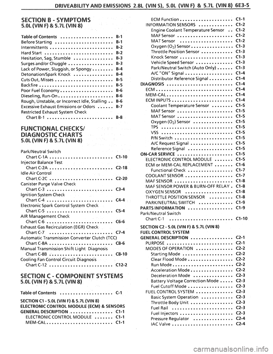
DRIVEABILITVAND EMISSIONS Z.$L (VIN 5). 5.OL (VIN F) & 5.7L (VIN 8) 6E3-5
SECTION B . SYMPTOMS
5.OL (VIN F) & 5.7L (VIN 8)
.................... Table of Contents B-1
................... Before Starting ... B-1
. lntermittents .................... ... B-2
Hardstart .......................... B-2
............... Hesitation. Sag. Stumble 8-3
Surges andlor Chuggle ................. B-3
........ Lack of Power. Sluggish. or Spongy 8-4
DetonationISpark Knock ............... B-4
...................... Cuts Out. Misses €3-5
Backfire ............................ B-5
Poor Fuel Economy .................... B-6
Dieseling. Run.On ..................... 8-6
Rough. Unstable. or Incorrect Idle. Stalling . . B-6
Excessive Exhaust Emissions or Odors ...... B-7
Restricted Exhaust System Check
Chart
B-1 ......................... B-8
FUNCTIONAL CHECKS1
DIAGNO%"FIC CHARTS
5.OL (VIN F) & 5.7L (WIN 8)
ParkINeutral Switch
. Chart C-1A .................... ... C1-10
Injector Balance Test
Chart C-2A
........................ C2-18
Idle Air Control
Chart C-2C
........................ C2-20
Canister Purge Valve Check
Chart C-3
......................... C3-4
Ignition System Check
ChartC-4
......................... C4-4
Electronic Spark Control System Check
Chart C-5
......................... C5-4
AIR Management Check
Chart C-6
......................... C6-6
Exhaust Gas Recirculation (EGR) Check
Chart C-7
........................ C7-4
Automatic Transmission Converter Clutch (TCC)
Chart
6-814 ........................ C8-6
Manual Transmission Shift Light Diagnosis
Chart C-8B
........................ C8-10
Cooling Fan Control Circuit Diagnosis
Chart C- 1 2
........................ C12-2
SECTION C . COMP0NEN"I"SVSTEMS
5.OL (VIN F) & 5.7L (WIN 8)
Table of Contents .................... C-1
SECTION
C1 . 5.OL (VIN F) & 5.7L (VIN 8)
ELECTRONIC CONTROL MODULE (ECM)
81 SENSORS
GENERAL DESCRIPTION
................ C1-1
ELECTRONIC CONTROL MODULE ....... C1-1
MEM.CAL ......................... C1-1
................... ECM Function. C1-1
INFORMATION SENSORS ............. C1-2
Engine Coolant Temperature Sensor . . C1-2
..................... MAF Sensor C1-2
.................... MAT Sensor C1-2
Oxygen (Oz) Sensor ..............a. C1-3
Throttle Position Sensor ............ C1-3
.................... Knock Sensor C1-3
Vehicle Speed Sensor .............. C1-3
ParkINeutral Switch (Auto Only) ...... C1-3
.................. A/C "ON" Signal C1-4
Distributor Reference Signal ......... C1-4
DIAGNOSIS ......................... C1-4
ECM ............................. C1-4
MEM.CAL ......................... C1-4
ECM INPUTS ....................... C1-4
Coolant Temperature Sensor ........ C1-5
..................... MAF Sensor C1-5
..................... MAT Sensor C1-5
Oxygen (Oz) Sensor ............... C1-5
TPS ........................... C1-5
VSS ........................... C1-5
...................... PIN Switch C1-5
A/C Request Signal ................ C1-5
Reference Signal ................. C1-5
ON-CAR SERVICE ..................... C1-5
ELECTRONIC CONTROL MODULE ....... C1-5
ECM or MEM-CAL REPLACEMENT ....... C1-6
Functional Check ................. C1-7
COOLANTSENSOR .................. C1-7
MAF SENSOR ...................... C1-8
MAF SENSOR POWER & BURN-OFF RELAY . C1-8
OXYGEN SENSOR .................. C1-8
THROTTLE POSITION SENSOR ......... C1-8
PARKINEUTRAL SWITCH ............. C1-9
................. PARTS INFORMATION C1-9
ParkINeutral Switch
Chart
C-1 ..................... ... C1-10
SECTION C2 . 5.0L (WIN F) & 5.7L (WIN 8)
FUEL CONTROL SYSTEM
................ GENERAL DESCRIPTION C2-1
......................... PURPOSE C2-1
.............. MODES OF OPERATION CZ-2
................... Starting Mode C2-2
Clear Flood Mode ................. CZ-2
....................... Run Mode CZ-2
................ Acceleration Mode C2-2
............... Decelerat~on Mode C2-3
Battery Voltage Correction Mode ..... C2-3
................. Fuel Cutoff Mode C2-3
.............. FUEL CONTROL SYSTEM C2-3
............ Basic System Operation CZ-3
................ Throttle Body Unit CZ-3
....................... Fuel Rail C2-3
.................... Fuel Injectors CZ-3
............... Pressure Regulator C2-4
....................... IAC Valve 62-4
Page 652 of 1825
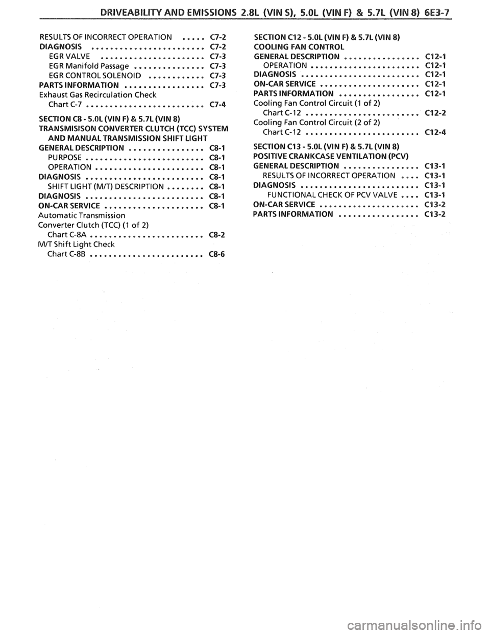
DRIVEABILITY AND EM10010NS 2.8L (WIN S). 5.8L (VIN F) & 5.7L (VlN 8) 6E3-7
RESULTS OF INCORRECT OPERATION ..... C7-2
DIAGNOSIS
....................... C7-2
EGRVALVE ...................... 0-3
EGR Manifold Passage ............... C7-3
EGR CONTROL SOLENOID ............ C7-3
PARTS INFORMATION
................. C7-3
Exhaust Gas Recirculation Check
Chart C-7
......................... C7-4
SECTION
C8 . 5.01 (VIN F) & 5.7L (VIN 8)
TRANSMISISON CONVERTER CLUTCH (TCC) SYSTEM
AND MANUAL TRANSMISSION SHIFT LIGHT
GENERAL DESCRIPTION
................ C8-1
PURPOSE ......................... C8-1
OPERATION ....................... C8-1
DIAGNOSIS ......................... C8-1
SHIFT LlGHT(M1T) DE5CRlPTlON ........ C8-1
DIAGNOSIS ......................... C8-1
ON-CAR SERVICE
..................... C8-1
Automatic Transmission
Converter Clutch
(TCC) (1 of 2)
Chart C-8A ........................ C8-2
MIT Shift Light Check
Chart C-8B
........................ C8-6
SECTION C12 . 5.OL (WIN F) & 5.7L (WIN 8)
eoOLlNe FAN CONTROL
GENERAL DESCRIPTION ................ C12-1
OPERATION ....................... C12-1
DIAGNOSIS ................... .. .... C12-1
ON-CAR SERVICE ..................... C12-1
PARTS INFORMATION .*............... ~12-1
Cooling Fan Control Circuit (I of 2)
Chart C-12 ........................ C12-2
Cooling Fan Control Circuit (2 of 2)
Chart C- 12 ........................ C9 2 -4
SECTION C13
. 5.OL (VIN F) & 5.7L (VIN 8)
POSITIVE CRANKCASE VENTILATION (PCV)
GENERALDESCRIPTION ................ 643-1
RESULTS OF INCORRECT OPERATION .... 613-9
DIAGNOSIS ......................... C13-1
FUNCTIONAL CHECK OF PCV VALVE .... C13-4
ON-CARSERVICE ..................... C13-2
PARTS INFORMATION ................. C13-2
Page 719 of 1825
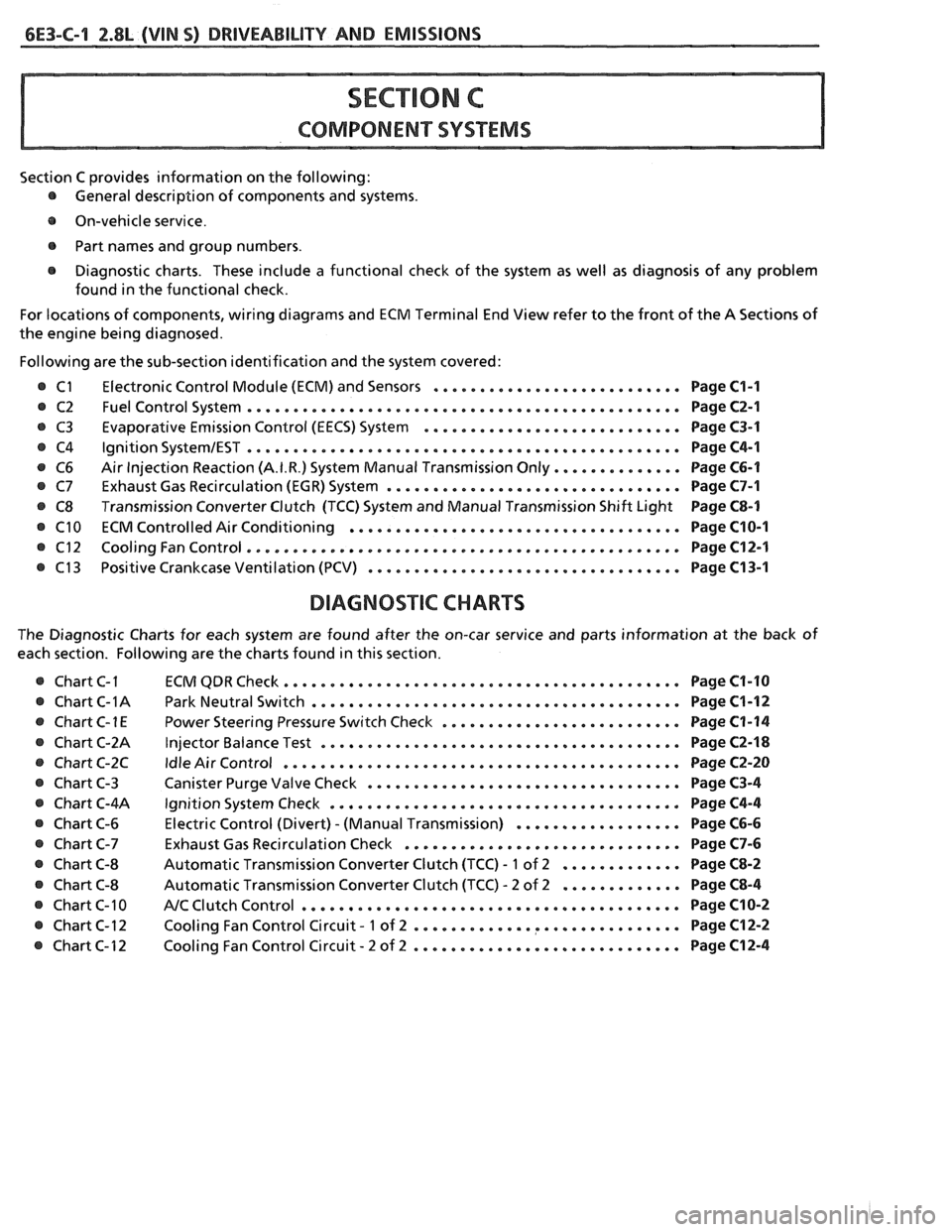
6E3-C-1 2.8L (VIN S) DRIVEABILITY AND EMISSIONS
COMPONENT SYSTEMS
Section C provides information on the following:
@ General description of components and systems .
e On-vehicle service .
@ Part names and group numbers .
@ Diagnostic charts . These include a functional check of the system as well as diagnosis of any problem
found in the functional check
.
For locations of components. wiring diagrams and ECM Terminal End View refer to the front of the A Sections of
the engine being diagnosed
.
Following are the sub-section identification and the system covered:
Electronic Control Module (ECM) and Sensors
........................... Page C1-I
Fuel Control System ............................................... Page C2-1
Evaporative Emission Control (EECS) System ............................ Page C3-1
Ignition SystemIEST ............................................... Page C4-1
Air Injection Reaction (A.I.R.) System Manual Transmission Only .............. Page C6-1
Exhaust Gas Recirculation (EGR) System ................................ Page C7-1
Transmission Converter Clutch (TCC) System and Manual Transmission Shift Light Page C8-1
ECM Controlled Air Conditioning .................................... Page C10-I
Cooling Fan Control ............................................... Page C12-1
Positive Crankcase Ventilation (PCV) .................................. Page C13-1
DIAGNOSTIC CHARTS
The Diagnostic Charts for each system are found after the on-car service and parts information at the back of
each section
. Following are the charts found in this section .
@ Chart C-I
@ Chart C-1A
e ChartC-1E
@ Chart C-2A
e Chart C-2C
@ Chart C-3
@ Chart C-4A
@ Chart C-6
@ Chart C-7
@ Chart C-8
@ Chart C-8
@ Chart C-10
@ Chart C-12
@ Chart C-12 ECM
QDR Check ........................................... Page C1-10
Park
Neutral Switch ........................................ Page C1-12
Power Steering Pressure Switch Check .......................... Page C1-14
Injector Balance Test ....................................... Page C2-18
Idle Air Control ........................................... Page C2-20
Canister Purge Valve Check .................................. Page C3-4
Ignition System Check ...................................... Page C4-4
Electric Control (Divert) . (Manual Transmission) .................. Page C6-6
Exhaust Gas Recirculation Check .............................. Page C7-6
Automatic Transmission Converter Clutch (TCC) . 1 of 2 ............. Page C8-2
Automatic Transmission Converter Clutch (TCC) . 2 of 2 ............. Page C8-4
NC Clutch Control ......................................... Page C10-2
. ............. ............... Cooling Fan Control Circuit 1 of 2 Page C12-2
. ............................. Cooling Fan Control Circuit 2 of 2 Page C12-4