1988 PONTIAC FIERO lights
[x] Cancel search: lightsPage 1311 of 1825
COOLANT FAN 1:
0 If the result is correct, go to section 6E for
ECM diagnosis.
1. Go to Table 2
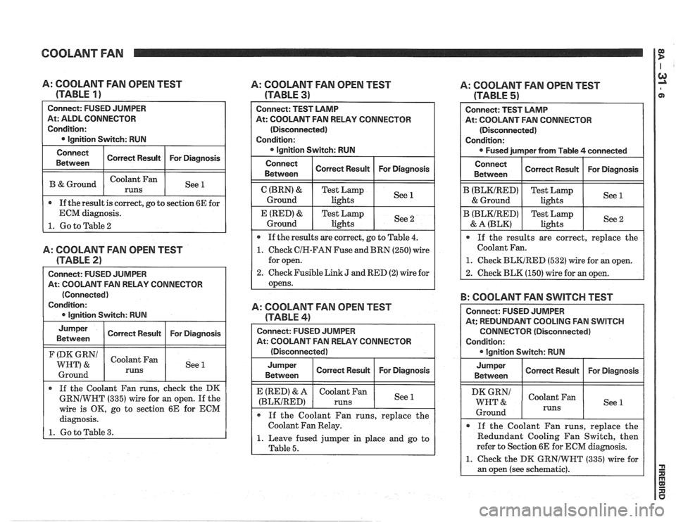
A: COOLANT FAN OPEN TEST
(TABLE
1 )
Connect: FUSED JUMPER
At: ALDL CONNECTOR
Condition:
@ lgnition Switch: RUN
A: COOLANT FAN OPEN TEST
(TABLE
2)
At: COOLANT FAN RELAY CONNECTOR
(Connected)
Condition:
0 lgnition Switch: RUN
Connect
Between
B & Ground
Jumper Correct Result For Diagnosis
Between
(DK GRN/ Coolant Fan
WHT) & See 1
1 Ground 1 runs 1 1
Correct Result
Coolant Fan
runs
If the Coolant Fan runs, check the DK
GRNIWNT (335) wire for an open. If the
wire is OK, go to section 6E for ECM
diagnosis.
1. Go to Table 3.
For Diagnosis
See 1
A: COOLANT FAN OPEN TEST
(TABLE
3)
Connect: TEST LAMP
At: COOLANT FAN RELAY CONNECTOR
(Disconnected)
Condition:
0 lgnition Switch: RUN
Connect Correct Result For Diagnosis
Between
lights
0 If the results are correct, go to Table 4.
1. Check CIN-FAN Fuse and BRN (250) wire
for open.
2. Check Fusible Link J and RED (2) wire for
opens.
A: COOLANT FAN OPEN TEST
(TABLE
4)
Connect: FUSED JUMPER
At: COOLANT FAN RELAY CONNECTOR
(Disconnected)
Jumper Correct Result For Diagnosis
Between
(BLKIRED)
If the Coolant Fan runs, replace the
Coolant Fan Relay.
1. Leave fused jumper in place and go to
I Table 5.
A: COOLANT FAN OPEN TEST
(TABLE
5)
B: COOLANT FAN SWITCH TEST
Connect: TEST LAMP
At: COOLANT FAN CONNECTOR
(Disconnected)
Condition:
Fused jumper from Table
4 connected
Connect
Between
B (BLKIRED)
& Ground
B (BLKIRED)
& A (BLK)
Connect: FUSED JUMPER
At; REDUNDANT COOLING FAN
SWITCH
CONNECTOR (Disconnected)
Condition:
@ lgnition Switch: RUN
If the results are correct, replace the
Coolant Fan.
1. Check BLKIRED (532) wire for an open.
2. Check BLK (150) wire for an open.
Correct Result
Test Lamp
lights
Test Lamp lights
Jumper
Between
WHT &
Ground
For Diagnosis
See 1
See 2
@ If the Coolant Fan runs, replace the
Redundant Cooling Fan Switch, then
refer to Section 6E for ECM diagnosis.
1. Check the DK GRNIWNT (335) wire for
an open (see schematic).
Correct Result
Coolant Fan
runs
For Diagnosis
See 1
Page 1312 of 1825
COOLANT FAN rn
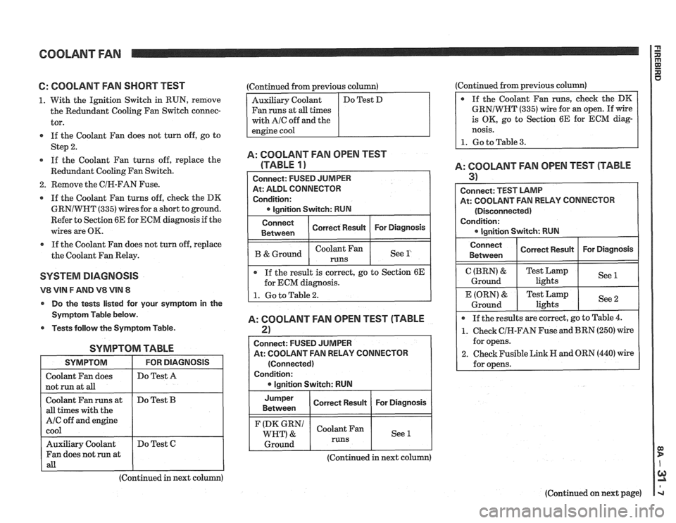
6: COOLANT FAN SHORT TEST
1. With the Ignition Switch in RUN, remove
the Redundant Cooling Fan Switch connec-
tor.
If the Coolant Fan does not turn off, go to
Step
2.
If the Coolant Fan turns off, replace the
Redundant Cooling Fan Switch.
2. Remove the CIR-FAN Fuse.
If the Coolant Fan turns off, check the DK
GRNIWHT
(335) wires for a short to ground.
Refer to Section 6E for ECM diagnosis if the
wires are OK.
a If the Coolant Fan does not turn off, replace
the Coolant Fan Relay.
SYSTEM DlAGNOSlS
V8 VIN F AND V8 VIN 8
Do the tests listed for your symptom in the
Symptom Table below.
Tests follow the Symptom Table.
SYMPTOM TABLE
I SYMPTOM I FORDIAGNOSIS I
I Do Test A I
I not run at aB I I
Coolant Fan runs at
all times with the
A/C off and engine
cool
(Continued in next column)
Do
Test
B
Auxiliary Coolant
Fan does not run at
all
:Continued from previous column)
Fan runs at
all times
with
AIC off and the
Do Test C (Continued
from previous column)
GRNIWNT
(335) wire for an open. If wire
is OK, go to Section 6E for ECM diag-
nosis.
1. Go to Table 3.
A: COOLANT FAN OPEN TEST
(TABLE
1)
At: ALDL CONNECTOR
Condition:
I B &Ground I I See l' I
Connect
Between
If the result is correct, go to Section 6E
for ECM diagnosis.
A: COOLANT FAN OPEN TEST (TABLE
2)
Correct Result
I
Connect: FUSED JUMPER
At: COOLANT FAN RELAY CONNECTOR For
Diagnosis
(Connected)
Condition: lgnition Switch: RUN
Jumper
I Correct Result I For Diagnosis I Between
(DK GRN1 Coolant Fan
WHT) & See 1
1 Ground 1 runs 1 1
A: COOLANT FAN OPEN TEST (TABLE
3) I
Connect: TEST LAMP
At: COOLANT FAN RELAY CONNECTOR
(Disconnected)
Condition:
Connect I Correct Rewn I For Diagnosis I I Between
C (BRN) &
Ground
If the results are correct, go to Table
4.
1. Check CIH-FAN Fuse and BRN (250) wire
for opens.
2. Check Fusible Link H and ORN (440) wire
for opens.
E (ORN)
&
Ground
(Continued in next column)
(Continued on next page)
Test Lamp
lights See
1
Test
Lamp
lights See 2
Page 1313 of 1825
COOLANT FAN
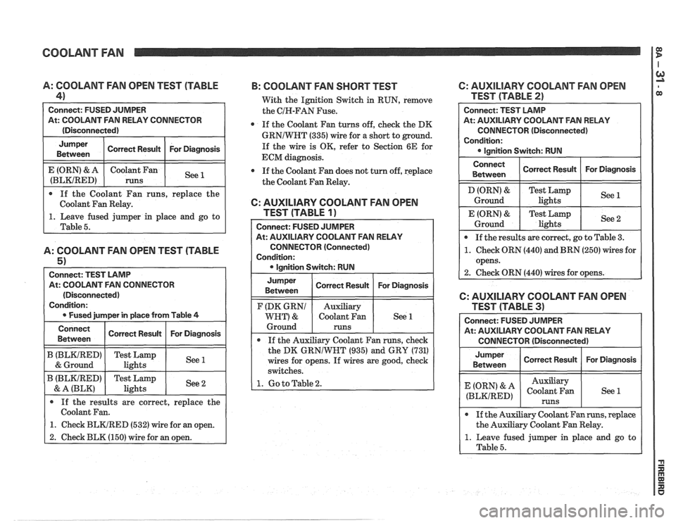
0 If the Coolant Fan runs, replace the
Coolant Fan Relay.
A: COOLANT FAN OPEN TEST (TABLE
4)
Connect: FUSED JUMPER
At: COOLANT FAN RELAY CONNECTOR
(Disconnected)
1. Leave fused jumper in place and go to
Table
5.
A: COOLANT FAN OPEN TEST (TABLE
5 1
Connect: TEST LAMP
At: COOLANT FAN CONNECTOR
(Disconnected)
Condition:
0 Fused jurnper in place from Table 4
For Diagnosis
See 1
Jumper
Between
E (ORN) & A
(BLKIRED)
Connect Correct Result For Diagnosis
Betvveen Correct
Result
coolant an
runs
B (BLKIRED) Test Lamp
1 & Ground 1 lights I See1
B (BLKIRED) Test Lamp
& A (BLK) I lights
If the results are correct, replace the
Coolant Fan.
1. Check BLKIRED (532) wire for an open.
2. Check BLK (150) wire for an open.
B: COOLANT FAN SHORT TEST 6: AUXILIARY COOLANT FAN OPEN
With the Ignition Switch in RUN, remove TEST (TABLE 2)
the CIH-FAN Fuse.
0 If the Coolant Fan turns off, check the DK
GRNIWNT (335) wire for a short to ground.
If the wire is OK, refer to Section 6E for
ECM diagnosis.
If the Coolant Fan does not turn off, replace
the Coolant Fan Relay.
6: AUXILIARY COOLANT FAN OPEN
TEST (TABLE
1)
Connect: FUSED JUMPER
At: AUXILIARY COOLANT FAN RELAY
CONNECTOR (Connected)
Condition:
0 Ianition Switch: RUN Connect:
TEST LAMP
At: AUXILIARY COOLANT
FAN RELAY
CONNECTOR (Disconnected)
Condition: Ignition Switch: RUN
Connect
Between
D (ORN) &
Ground
E (ORN)
&
Ground
Jumper
Between
If the Auxiliary Coolant Fan runs, check
the DK
GRNlWNT (935) and GRY (731)
wires for opens. If wires are good, check
switches.
1. Go to Table 2.
F (DK GRNl
WHT) &
Ground If
the results are correct, go to Table
3.
1. Check ORN (440) and BRN (250) wires for
opens.
2. Check ORN
(440) wires for opens.
Correct Result
Test Lamp
lights
Test Lamp lights
Correct Result For
Diagnosis
See 1
See 2
Auxiliary
Coolant Fan
runs
Connect: FUSED JUMPER
At: AUXILIARY COOLANT FAN RELAY
CONNECTOR (Disconnected)
For
Diagnosis See 1
Jumper
Between
(ORN' & A
(BLKIRED)
6: AUXILIARY COOLANT FAN OPEN
0 If the Auxiliary Coolant Fan runs, replace
the Auxiliary Coolant Fan Relay.
1. Leave fused jumper in place and go to
Table
5.
Correct Result
Auxiliary
Coolant Fan
runs
For Diagnosis
See 1
Page 1314 of 1825
COOLANT FAN
C: AUXILIARY COOLANT FAN OPEN
TEST (TABLE
41
At: AUXILIARY COOLANT FAN CONNECTOR
(Disconnected)
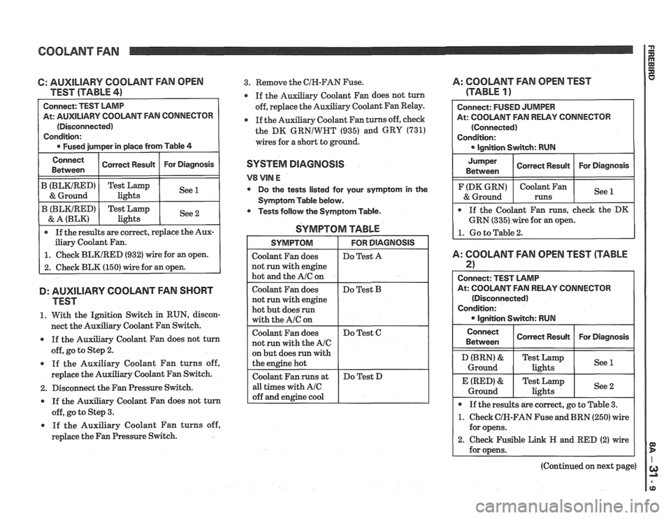
iliary Coolant Fan.
1. Check BLKIRED (932) wire for an open.
2. Check BLK (150) wire for an open.
D: AUXILIARY COOLANT FAN SHORT
TEST
1. With the Ignition Switch in RUN, discon-
nect the Auxiliary Coolant Fan Switch.
If the Auxiliary Coolant Fan does not turn
off, go to Step
2.
If the Auxiliary Coolant Fan turns off,
replace the Auxiliary Coolant Fan Switch.
2. Disconnect the Fan Pressure Switch.
If the Auxiliary Coolant Fan does not turn
off, go to Step
3.
* If the Auxiliary Coolant Fan turns off,
replace the Fan Pressure Switch.
3. Remove the CIN-FAN Fuse. A: COOLANT FAN OPEN TEST
y Coolant Fan does not turn (TABLE 1 )
Auxiliary Coolant Fan Relay.
Coolant Fan turns off, check
the DK
GRNIWRT (935) and GRY (731)
wires for a short to ground.
SYSTEM DIAGNOSIS
V8 VIN E
Do the tests listed for your symptom in the
Symptom Table below.
* Tests follow the Symptom Table.
SYMPTOM TABLE
but does run with
At: COOLANT FAN RELAY CONNECTOR
A: COOLANT FAN OPEN TEST (TABLE
2)
Connect: TEST LAMP
At: COOLANT FAN RELAY CONNECTOR
(Disconnected)
Condition:
Ignition Switch: RUN
Connect
Between
I Conen Resun I For Diagnosis I
Ground lights
* If the results are correct, go to Table 3.
1. Check CIK-FAN Fuse and BRN (250) wire
for opens.
2. Check Fusible Link H and RED (2) wire
(Continued on next page)
Page 1315 of 1825
COOLANT FAN I $
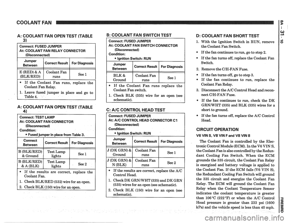
A: COOLANT FAN OPEN TEST (TABLE
3)
Connect: FUSED JUMPER
At: COOLANT FAN RELAY CONNECTOR
(Disconnected)
Jumper Correct Result For Diagnosis
Between
1. Leave fused jumper in place and go to
Table
4.
E (RED) & A
(BLKIRED)
A: COOLANT FAN OPEN TEST (TABLE
41
Connect: TEST LAMP
At: COOLANT FAN CONNECTOR
(Disconnected)
Condition:
Fused jumper in place from Table
3.
If the Coolant Fan runs, replace the
Coolant Fan Relay. Coolant
Fan
runs
-. -. See --
B: COOLANT FAN SWITCH TEST
Connect
Between
B (BLKtRED)
& Ground
B (BLKIRED)
& A (BLK)
Connect: FUSED JUlVlPER
At: COOLANT FAN SWITCH CONNECTOR
(Disconnected)
Condition: lgnition Switch: RUN
Jumper
Between Correct
Result For Diagnosis
Coolant Fan
Ground
runs
If the Coolant Fan runs replace the
Coolant Fan switch.
1. Check BLK (335) wire for an open (see
schematic).
6: AIC CONTROL HEAD TEST
If the results are correct, replace the
Coolant Fan.
1. Check BLKIRED (532) wire for an open.
2. Check BLK (150) wire for an open.
Correct Result
Test Lamp
lights
Test Lamp
lights
Connect: FUSED JUMPER
At:
A/C CONTROL HEAD CONNECTOR Cl
(Disconnected)
Condition:
lgnition Switch: RUN
For Diagnosis
See 1
See 2
Jumper
Between I Correct Result I For Diagnosis I
".' Ground
J (DK GRN) & Coolant Fan See N (BLK) runs
If the results are correct, replace the
AIC
Control Head.
1. Check DK GRNIWHT (335) and DK GRN
(535) wires for an open (see schematic).
2. Check BLK (150) wire for an open (see
schematic).
D: COOLANT FAN SHORT TEST
1. With the Ignition Switch in RUN, remove
the Coolant Fan Switch.
If the fan continues to
run, go to step 2.
If the fan turns off, replace the Coolant Fan
Switch.
2. Remove the CIH-FAN Fuse.
If the fan turns off, go to step 3.
If the fan continues to run, replace the
Coolant Fan Relay.
3. Disconnect the
AIC Control Head and recon-
nect CIH-FAN Fuse.
If the fan continues to run,
check the DK
GRNIWHT (335) and BLK (335) wires for a
short to ground.
If the fan turns off, replace the
AIC Control
Head.
CIRCUIT OPERATION
V6 VIN S, V8 VIN F and V8 VIN 8
The Coolant Fan is controlled by the Elec-
tronic Control Module (ECM). In the V6 VIN S,
the Coolant Fan is also controlled by the Redun-
dant Cooling Fan Switch. When the ECM
grounds the 335 circuit, the Coolant Fan Relay
is energized and battery voltage is applied to
the Coolant Fan.
If the ECM fails (V6 VIN S),
the Redundant Cooling Fan Switch will ground
the 335 circuit and energize the Coolant Fan
Relay. The ECM will ground the Coolant Fan
Relay when the Coolant Temperature Sensor
indicates the coolant temperature is greater
than 106
OC (222 OF) or when the AIC Control
Head pressure is greater than 233 psi (1600
kPa) and the vehicle speed is less than 40 mph.
Page 1324 of 1825
CRUISE CONTROL 2
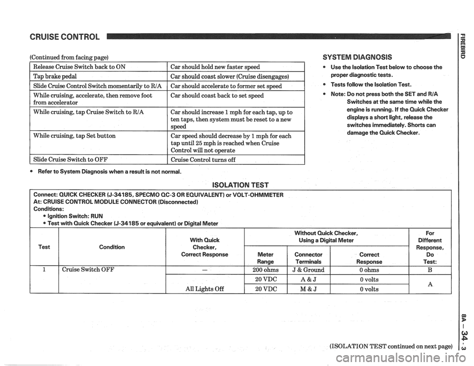
I Slide Cruise Control Switch momentaril~ to RIA I Car should accelerate to former set s~eed I
(Continued from facing page)
--
While cruising, accelerate, then remove foot I car should coast back to set speed
from accelerator
Release Cruise Switch
back to ON
Tap brake pedal
I While cruising, tap Cruise Switch to RIA I Car should increase 1 mph for each tap, up to I
Car should hold new faster speed
Car should coast slower (Cruise disengages)
tap
until 25 mph is reached when cruise
Control will not o~erate I
While cruising, tap Set button
1 Slide Cruise Switch to OFF ten
taps, then system must be reset to a new
speed
Car speed should decrease by
1 mph for each
I Cruise Control turns off 1
0 Refer to System Diagnosis when a result is not normal.
SYSTEM DIAGNOSIS
@ Use the isolation Test below to choose the
proper diagnostic tests.
@ Tests follow the Isolation Test.
Note: Do not press both the SET and RIA
Switches at the same time while the
engine is running. If the Quick Checker
displays
a short light, release the
switches immediately. Shorts can
damage the Quick Checker.
lSOLATlON TEST
Connect: QUICK CHECKER (J-34185, SPECMO QC-3 OR EQUIVALENT) or VOLT-OHMMETER
At: CRUISE CONTROL MODULE CONNECTOR (Disconnected)
Conditions:
@ Ignition Switch: RUN
Test with Quick Checker
(J-34185 or equivalent) or Digital Meter
Test Condition
Cruise Switch OFF
(ISOLATION TEST continued on next page)
All Lights Off
With Quick
Checker,
Correct Response
-
20 VDC
20 VDC
For
Different
Response, Do
Test:
B
Without Quick Checker,
Using a Digital Meter
A&J
M&J
Meter
Range
200 ohms
0 volts
0 volts
Connector
Terminals
J & Ground
A
Correct
Response
0 ohms
Page 1325 of 1825
CRUISE CONTROL
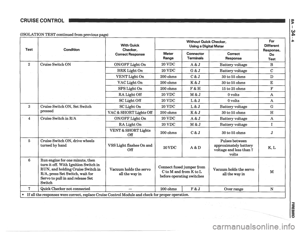
(ISOLATION
Test
2 3
4
5
6
7
If all
TEST continued from previous page)
Condition
Cruise Switch ON
Cruise Switch ON, Set Switch
pressed
Cruise Switch
in RIA
Cruise Switch ON, drive wheels
turned by hand
Run engine for one minute, then
turn it off. With Ignition Switch in
RUN, and holding Cruise Switch
in
RIA, press Set Switch, wait for
Servo to pull
in and release Set
Switch
Quick Checker not connected
the responses were correct, replace Cruise
With Quick
Checker,
Correct Response
ONIOFF Light On
BRK Light On
VENT Light On
VAC Light On
SPS Light On
RA Light Off
SC Light Off
SC Light On
VAC
& SNORT Lights Off
ONIOFF Light On
RA Light On
VENT & SNORT Lights
Off
VSS Light flashes On and
Off
Vacuum holds the servo
all theway in
-
Control Module and check
Without Quick Checker, For
Using
a Digital Meter Different
Meter
Range
20 VDG
20 VDC
200 ohms
200 ohms
200 ohms
20 VDC
20 VDC
20 VDC
200 ohms
20 VDC
20 VDC
200 ohms
20VDC
Connector Terminals
A&J
G&J
C&J
K&J
F&N
M&J
L&J
L&J
K&J
A&J
M&J
C&J
A&D
Response,
Correct Do
Response Test
Battery voltage B
Battery voltage C
30 to 55 ohms D
30 to 55 ohms E
15 to 25 ohms F
0 volts A
0 volts
A
Battery voltage G
30 to 55 ohms N
Battery voltage A
Battery voltage
I
30 to 55 ohms J
Pulses between
approximately battery
voltage and less than
7 K, L
volts
Connect fused jumper from
CtoMandfromKtoL
before operating switches
200ohms 1 F&J
for proper operation.
Vacuum holds the servo
all the way in M
Over range N
Page 1327 of 1825
CRUISE CONTROL
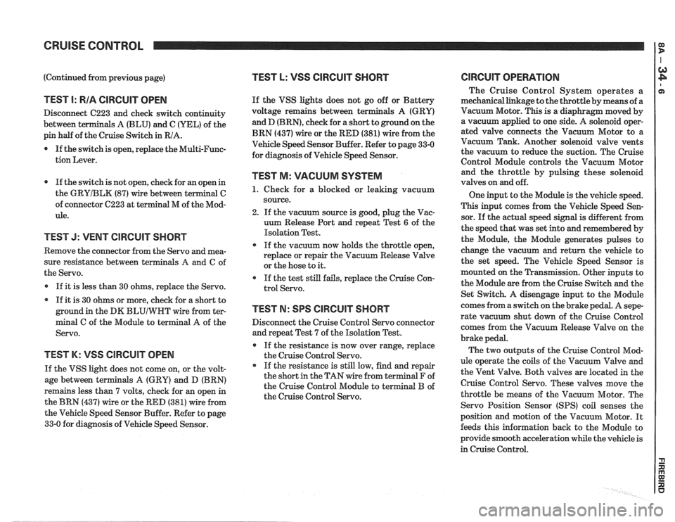
(Continued from previous page)
TEST I: RIA CIRCUIT OPEN
Disconnect C223 and check switch continuity
between terminals A (BLU) and C (YEL) of the
pin half of the Cruise Switch in RIA.
0 If the switch is open, replace the Multi-Func-
tion Lever.
If the switch is not open, check for an open in
the
GRYIBLK (87) wire between terminal C
of connector C223 at terminal M of the Mod-
ule.
TEST J: VENT CIRCUIT SHORT
Remove the connector from the Servo and mea-
sure resistance between terminals
A and C of
the Servo.
If it is less than 30 ohms, replace the Servo.
If it is 30 ohms or more, check for a short to
ground in the DK
BLUIWHT wire from ter-
minal C of the Module to terminal A of the
Servo.
TEST K: VSS ClRCUlT OPEN
If the VSS light does not come on, or the volt-
age between terminals A (GRY) and D (BRN)
remains less than 7 volts, check for an open in
the BRN (437) wire or the RED (381) wire from
the Vehicle Speed Sensor Buffer. Refer to page
33-0 for diagnosis of Vehicle Speed Sensor.
TEST L: VSS CIRCUIT SHORT
If the VSS lights does not go off or Battery
voltage remains between ter
and D
(BRN), check for a short to ground on the
BRN (437) wire or the RED (381) wire from the
Vehicle Speed Sensor Buffer. Refer to page 33-0
for diagnosis of Vehicle Speed Sensor.
TEST M: VACUUM SYSTEM
1. Check for a blocked or leaking vacuum
source.
2. If the vacuum source is good, plug the Vac-
uum Release Port and repeat Test
6 of the
Isolation Test.
If the vacuum now holds the throttle open,
replace or repair the Vacuum Release Valve
or the hose to it.
If the test still fails, replace the Cruise Con-
trol Servo.
TEST N: SPS CIRCUIT SHORT
Disconnect the Cruise Control Servo connector
and repeat Test 7 of the Isolation Test.
If the resistance is now over range, replace
the Cruise Control Servo.
If the resistance is still low, find and repair
the short in the TAN wire from terminal F of
the Cruise Control Module to terminal B of
the Cruise Control Servo.
ClRCUlT OPERATION
The Cruise Control System operates a
mechanical linkage to the throttle by means of a
Vacuum Motor. This is a diaphragm moved by
a vacuum applied to one side. A solenoid oper-
ated valve connects the Vacuum Motor to a
Vacuum Tank. Another solenoid valve vents
the vacuum to reduce the suction. The Cruise
Control Module controls the Vacuum Motor
and the throttle by pulsing these solenoid
valves on and off.
One input to the Module is the vehicle speed.
This input comes from the Vehicle Speed Sen-
sor. If the actual speed signal is different from
the speed that was set into and remembered by
the Module, the Module generates pulses to
change the vacuum and return the vehicle to
the set speed. The Vehicle Speed Sensor is
mounted on the Transmission. Other inputs to
the Module are from the Cruise Switch and the
Set Switch. A disengage input to the Module
comes from a switch on the brake pedal. A
sepe-
rate vacuum shut down of the Cruise Control
comes from the Vacuum Release Valve on the
brake pedal.
The two outputs of the Cruise Control Mod-
ule operate the coils of the Vacuum Valve and
the Vent Valve. Both valves are located in the
Cruise Control Servo. These valves move the
throttle be means of the Vacuum Motor. The
Servo Position Sensor
(SPS) coil senses the
position and motion of the Vacuum Motor. It
feeds this information back to the Module to
provide smooth acceleration while the vehicle is
in Cruise Control.