1988 PONTIAC FIERO lights
[x] Cancel search: lightsPage 1212 of 1825
POWER DISTRIBUTION
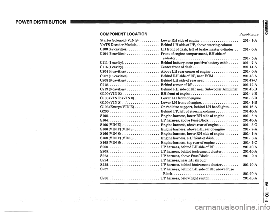
COMPONENT LOCATION Page-Figure
Starter Solenoid (VIN
S) .......... Lower RH side of engine ....................
VATS Decoder Module ............ Behind LH side of IIP. above steering column
el00 (42 cavities) ................ LH front of dash. left of brake master cylinder ..
C104 (6 cavities) ................. Front of engine compartment. RH side of
radiator
.................................
Clll(1 cavity) ................... Behind battery. near positive battery cable .....
C115 (1 cavity) ................... Center front of dash ........................
C204 (4 cavities) ................. Above LH rear corner of engine ..............
C207 (15 cavities) ................ Behind RH side of IIP. near ECM .............
C208 (8 cavities) ................. Behind LH side of rear seat ..................
(2218 ........................... Behind center of IIP ........................
C219 (6 cavities) ................. Behind RH side of IIP. near Subwoofer Amplifier
G100 (VIN E) ................... RH front of engine .........................
G100 (VIN F) (VIN 8) ............. Lower LH front of engine ....................
G100 (VIN S) .................... Lower LH front of engine ....................
6103 (Except VIN E) ............. On radiator support. behind LH headlights .....
6200 .......................... Behind IIP. left of steering column ............
S108 ........................... Engine harness. lower RH side of engine .......
S164 ........................... IIPharness. aboveFuseBlock ................
S166 (VIN E) .................... Engine harness. above rear of engine ..........
S166 (VIN F) (VIN 8) ............. Engine harness. above LH rear of engine .......
S166 (VIN S) .................... Engine harness. lower RH side of engine .......
S168 (VIN F) (VIN 8) ............. Engine harness. RH front of dash .............
S168 (VIN S) .................... Engine harness. top rear of engine ............
S200 ........................... IIP harness. behind LH side of IIP ............
S205 ........................... IIP harness. behind instrument cluster .........
S223 ........................... IIP harness. above Fuse Block ................
S224 ........................... IIP harness. near LH shroud
S225
........................... IIP harness. behind instrument cluster .........
S232 ........................... IIP harness. behind LH side of IIP. above Fuse
................................... Block
S236
........................... IIP harness. below light switch ...............
Page 1213 of 1825
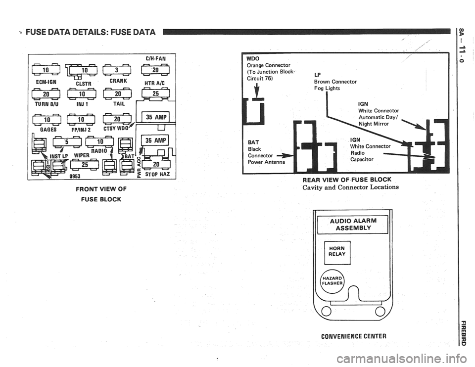
FUSE DATA DETAILS: FUSE DATA
E:ge Connector
(To Junction
Block- LP
Brown Connector
Fog Lights
I
ite Connector
White Connecto
REAR VlEW OF FUSE BLOCK
FRONT VlEW OF
FUSE BLOCK Cavity and Connector Locations
CONVENIENCE CENTER
Page 1231 of 1825
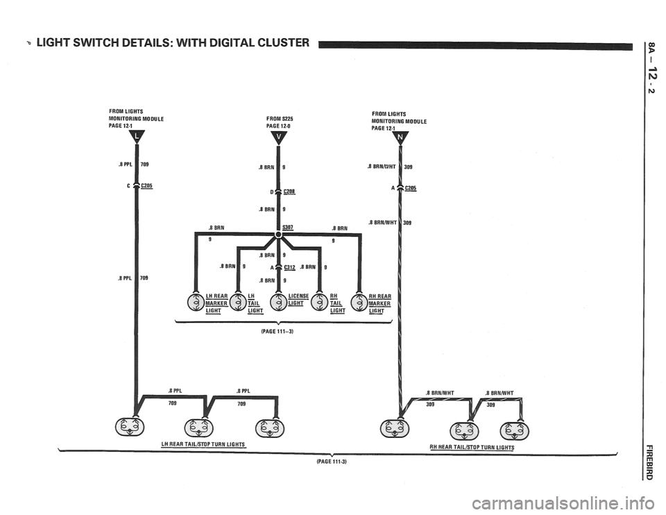
LIGHT SWlTCH DETAILS: WITH DIGITAL CLUSTER --
FROM LIGHTS FROI!! LIGHTS
MONITORING MODULE FROM S225 MONITORING MODULE
(PAGE
1113)
Page 1232 of 1825
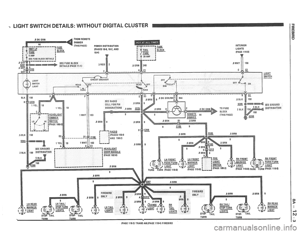
LIGHT SWITCH DETAILS: WITHOUT DIGITAL CLUSTER
FROM REMOTE
(THIS PAGE) POWER DISTRIBUTION
INTERIOR (PAGES 10-0.10-2. AND LIGHTS
.5 BRN
(PAGE 110-3) TRANS AM;(PAGE 110-4) FIREBIRD
Page 1296 of 1825
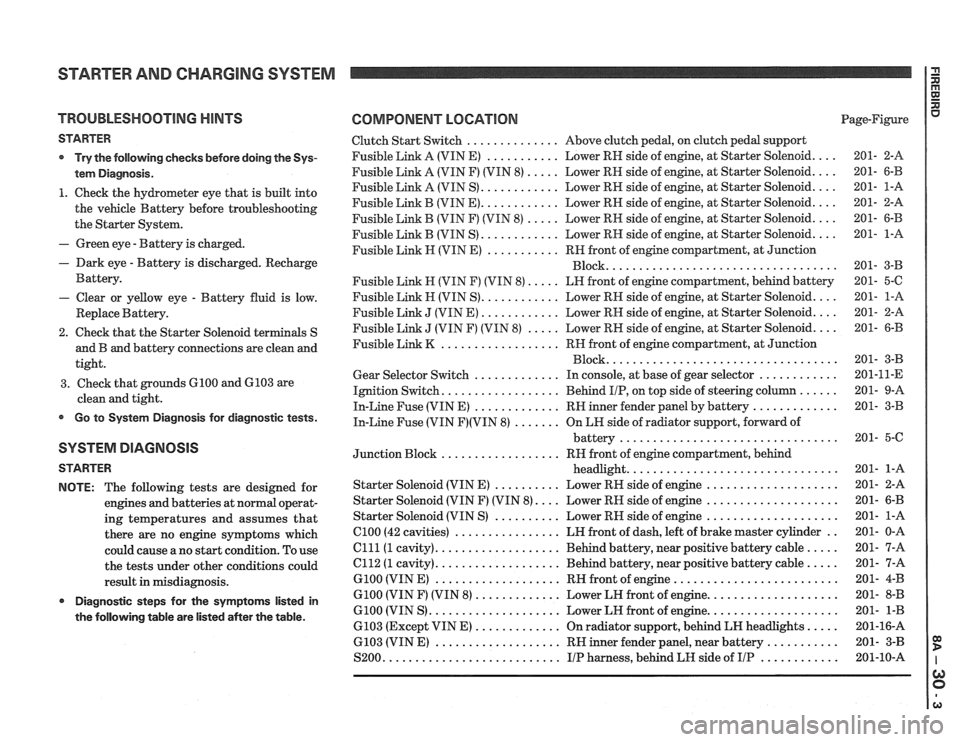
TROUBLESHOOTING HINTS
STARTER
Try the following checks before doing
the Sys-
tem Diagnosis
.
1 . Check the hydrometer eye that is built into
the vehicle Battery before troubleshooting
the Starter System
.
. Green eye . Battery is charged .
. Dark eye . Battery is discharged . Recharge
Battery
.
- Clear or yellow eye . Battery fluid is low .
Replace Battery .
2 . Check that the Starter Solenoid te
and B and battery
connections are clean and
tight
.
3 . Check that grounds 6100 and 6103 are
clean and tight
.
Go to System Diagnosis for diagnostic tests .
SYSTEM DIAGNOSIS
STARTER
NOTE:
The following tests are designed for
engines and batteries at normal operat-
ing temperatures and assumes that
there are no engine symptoms which
could cause a no start condition
. To use
the tests under other conditions could
result in misdiagnosis
.
Diagnostic steps for the symptorns listed in
the following table are listed after the table
.
COMPONENT LOCATION Page-Figure
Clutch Start Switch
.............. Above clutch pedal. on clutch pedal support
Fusible Link A (VIN E)
........... Lower RH side of engine. at Starter Solenoid .... 201- 2-A
Fusible Link A (VIN F) (VIN
8) ..... Lower RH side of engine. at Starter Solenoid .... 201- 6-B
Fusible Link A (VIN S)
............ Lower RH side of engine. at Starter Solenoid .... 201- 1-A
Fusible Link B (VIN
E) ............ Lower RH side of engine. at Starter Solenoid .... 201- 2-A
Fusible Link
B (VIN F) (VIN 8) ..... Lower RH side of engine. at Starter Solenoid .... 201- 6-B
Fusible Link B (VIN S)
............ Lower RH side of engine. at Starter Solenoid .... 201- 1-A
Fusible Link
H (VIN E) ........... RN front of engine compartment. at Junction
................................... Block 201- 3-B
Fusible Link
H (VIN F) (VIN 8) ..... LH front of engine compartment. behind battery 201- 5-C
Fusible
Link H (VIN S) ............ Lower RH side of engine. at Starter Solenoid .... 201- 1-A
Fusible Link
J (VIN E) ............ Lower RH side of engine. at Starter Solenoid .... 201- 2-A
Fusible Link
J (VIN F) (VIN 8) ..... Lower RH side of engine. at Starter Solenoid .... 201- 6-B
Fusible Link
K .................. RH front of engine compartment. at Junction
................................... Block 201- 3-B
Gear Selector Switch
............. In console. at base of gear selector ............ 201-11-E
Ignition Switch
.................. Behind IIP. on top side of steering column ...... 201- 9-A
In-Line Fuse (VIN E)
............. RH inner fender panel by battery ............. 201- 3-B
In-Line Fuse (VIN F)(VIN 8) ....... On LN side of radiator support. forward of
battery
................................. 201- 5-C
Junction Block
.................. RH front of engine compartment. behind
headlight
................................ 201- 1-A
Starter Solenoid (VIN
E) .......... Lower RH side of engine .................... 201- 2-A
Starter Solenoid (VIN F) (VIN
8) .... Lower RH side of engine .................... 201- 6-B
Starter Solenoid (VIN S)
.......... Lower RH side of engine .................... 201- 1-A
el00 (42 cavities) ................ LH front of dash. left of brake master cylinder .. 201- 0-A
Clll(1 cavity) ................... Behind battery. near positive battery cable ..... 201- 7-A
el12 (1 cavity) ................... Behind battery. near positive battery cable ..... 201- 7-A
G100 (VIN E) ................... RH front of engine ......................... 201- 4-B
G100 (VIN F) (VIN 8) ............. Lower LH front of engine .................... 201- 8-B
6100 (VIN S) .................... Lower LH front of engine .................... 201- 1-B
6103 (Except VIN
E) ............. On radiator support. behind LH headlights ..... 201-16-A
6103 (VIN
E) ................... RH inner fender panel. near battery ........... 201- 3-B
S200
........................... IIP harness. behind LH side of IIP ............ 201-10-A
Page 1303 of 1825
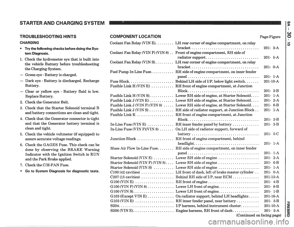
STARTER AND CHARGING SYSTEM
TROUBLESHOOTING HINTS
CHARGING
* Try the following checks before doing the Sys-
tem Diagnosis
.
1 . Check the hydrometer eye that is built into
the vehicle Battery before troubleshooting
the Charging System
.
- Green eye . Battery is charged .
. Dark eye . Battery is discharged . Recharge
Battery
.
- Clear or yellow eye . Battery fluid is low .
Replace Battery .
2 . Check the Generator Belt .
3 . Check that the Starter Solenoid terminal B
and battery connections are clean and tight
.
4 . Check that the Generator connector is tight
and that the Generator battery terminal is
clean and tight
.
5 . Check the vehicle voltmeter (if equipped) to
assure accurate voltage readings
.
6 . Check the GAGES Fuse . This check can be
done by observing the BRAKE Warning
Indicator with the Ignition Switch in RUN
and the Park Brake applied
.
7 . Check the GIN-FAN Fuse .
Go to System Diagnosis for diagnostic tests .
COMPONENT LOCATION Page-Figure
Coolant Fan Relay (VIN
E) ......... LH rear corner of engine compartment. on relay
bracket
................................. 201- 3-A
Coolant Fan Relay (VIN F) (VIN 8)
. . Front of engine compartment. RH side of
radiator support
.......................... 201- 5-A
Coolant Fan Relay (VIN S)
......... LN rear corner of engine compartment. on relay
bracket
................................. 201- 0-A
Fuel Pump In-Line Fuse
........... RH side of engine compartment. on inner fender
panel
................................... 201- 1-A
Fuse Block
...................... Behind LN side of IIP. below light switch ....... 201-10-A
Fusible Link H (VIN E)
........... RH front of engine compartment. at Junction
................................... Block 201- 3-B
Fusible Link
H (VIN S) ............ Lower RN side of engine. at Starter Solenoid .... 201- 1-A
Fusible Link
J (VIN E) ............ Lower RH side of engine. at Starter Solenoid .... 201- 2-A
Fusible Link
J (VIN F) (VIN 8) ..... Lower RH side of engine. at Starter Solenoid .... 201- 6-B
Fusible Link
J (VIN S) ............ RH side of radiator support. at Junction Block .. 201- 1-A
Fusible Link
K .................. RH front of engine compartment. at Junction
................................... Block 201- 3-B
In-Line Fuse (VIN E)
............. RH inner fender panel by battery ............. 201- 3-B
In-Line Fuse (VIN
F)(VIN 8) ....... On LH side of radiator support. forward of
................................. battery 201- 5-6
.................. Junction Block RH
front of engine compartment. behind
................................ headlight 201- 1-A
........ Mass Air Flow In-Line Fuse RR side of engine compartment. on inner fender
................................... panel 201- 1-A
Starter Solenoid (VIN E)
.......... Lower RH side of engine .................... 201- 2-A
Starter Solenoid (VIN F) (VIN
8) .... Lower RH side of engine .................... 201- 6-B
Starter Solenoid (VIN S)
.......... Lower RN side of engine .................... 201- 1-A
el00 (42 cavities) ................ LH front of dash. left of brake master cylinder .. 201- 0-A
C207 (15 cavities)
................ Behind RH side of IIP. near ECM ............. 201-13-A
G100 (VIN E) ................... RH front of engine ......................... 201- 4-B
G100 (VIN F) (VIN 8) ............. Lower LH front of engine .................... 201- 8-B
G100 (VIN S) .................... Lower LH front of engine .................... 201- 1-B
6103 (Except VIN E) ............. On radiator support. behind LH headlights ..... 201-16-A
6.103 (VIN E) ................... RH inner fender panel. near battery ........... 201- 3-B
S204
........................... IIP harness. behind instrument cluster ......... 201-10-A
S206 (VIN
E) .................... Engine harness. RH front of dash ............. 201- 2-A
(Continued on facing page)
Page 1309 of 1825
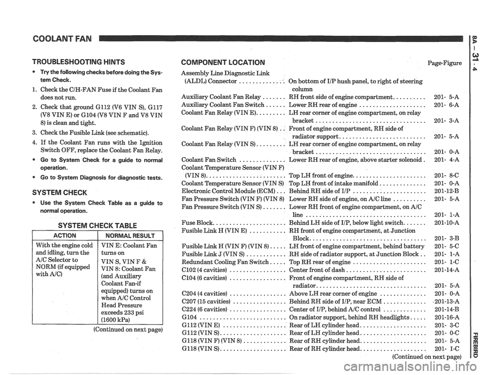
COOLANT FAN I g
TROUBLESHOOTING HINTS
@ Try the following checks before doing the Sys-
tem Check.
1. Check the CIH-FAN Fuse if the Coolant Fan
does not run.
2. Check that ground 6112 (V6 VIN S), 6117
(V8 VIN E) or 6104 (V8 VIN F and V8 VIN
8) is clean and tight.
3. Check the Fusible Link (see schematic).
4.
If the Coolant Fan runs with the Ignition
Switch OFF, replace the Coolant Fan Relay.
@ Go to System Check for a guide to normal
operation.
Go to System Diagnosis for diagnostic tests.
SYSTEM CHECK
Use the System Checlc Table as a guide to
normal operation.
SYSTEM CHECK TABLE
I ACTION I NORMALRESULT 1
COMPONENT LOCATION Page-Figure
Assembly Line Diagnostic Link
(ALDL) Connector .............. On bottom of IIP hush panel, to right of steering
column
Auxiliary Coolant Fan Relay
....... RH front side of engine compartment. ......... 201- 5-A
Auxiliary Coolant Fan Switch
...... Lower RN rear of engine .................... 201- 6-A
Coolant Fan Relay (VIN
E). ........ LH rear corner of engine compartment, on relay
bracket
................................. 201- 3-A
Coolant Fan Relay (VIN F) (VIN 8)
. . Front of engine compartment, RN side of
radiator support.
......................... 201- 5-A
Coolant Fan Relay (VIN S)
......... LH rear corner of engine compartment, on relay
................................. bracket 201- 0-A
Coolant Fan Switch
.............. Lower RH rear of engine, above starter solenoid . 201- 4-A
Coolant Temperature Sensor (VIN F)
(VIN 8).
....................... Top LW front of engine. ..................... 201- 8-C
Coolant Temperature Sensor (VIN S) Top LH front of intake manifold.
............. 201- 0-A
Electronic Control Module (ECM)
... Behind RN side of IIP ...................... 201-12-B
Fan Pressure Switch (VIN F) (VIN 8) Lower RH side of engine, on
AIC line .......... 201- 5-A
Fan Pressure Switch (VIN S)
....... Lower RN front of engine compartment, on AIC
line .................................... 201- 1-A
Fuse Block.
..................... Behind LN side of IIP, below light switch. ...... 201-10-A
Fusible Link
N (VIN E) ........... RH front of engine compartment, at Junction
Block ................................... 201- 3-B
Fusible Link N (VIN F) (VIN 8).
.... LN front of engine compartment, behind battery 201- 5-C
Fusible Link
J (VIN S) ............ RN side of radiator support, at Junction Block .. 201- 1-A
Redundant Cooling Fan Switch.
.... Top RW rear of engine ...................... 201- 1-6
C102 (4 cavities) ................. Center front of dash. ....................... 201-14-A
6104 (6 cavities)
................. Front of engine compartment, RH side of
................................ radiator. 201- 5-A
C204 (4 cavities) ................. Above LH rear corner of engine .............. 201- 0-A
C207 (15 cavities)
................ Behind RH side of IIP, near ECM ............. ,201-13-A
C224 (6 cavities) ................. Center of IIP, behind AIC control ............. 201-14-B
6104
.......................... On radiator support, behind RN headlights. .... 201-16-A
6112 (VIN E)
................... Rear of LN cylinder head. ................... 201- 3-C
6112 (VIN S)
.................... Rear of LH cylinder head. ................... 201- 0-C
6118 (VIN F) (VIN 8)
............. Rear of RH cylinder head. ................... 201- 5-A
6118 (VIN S)
.................... Rear of RH cylinder head. ................... 201- 1-C
(Continued on next page)
With
the engine cold
and idling, turn the
AIC Selector to
NORM (if equipped
with Ale)
VIN E: Coolant Fan
turns on
VIN S, VIN
F &
VIN 8: Coolant Fan
(and Auxiliary
Coolant Fan-if
equipped) turns on
when
A/C Control
Head Pressure
exceeds 233 psi
(1600
kPa)
(Continued on next page)
Page 1310 of 1825
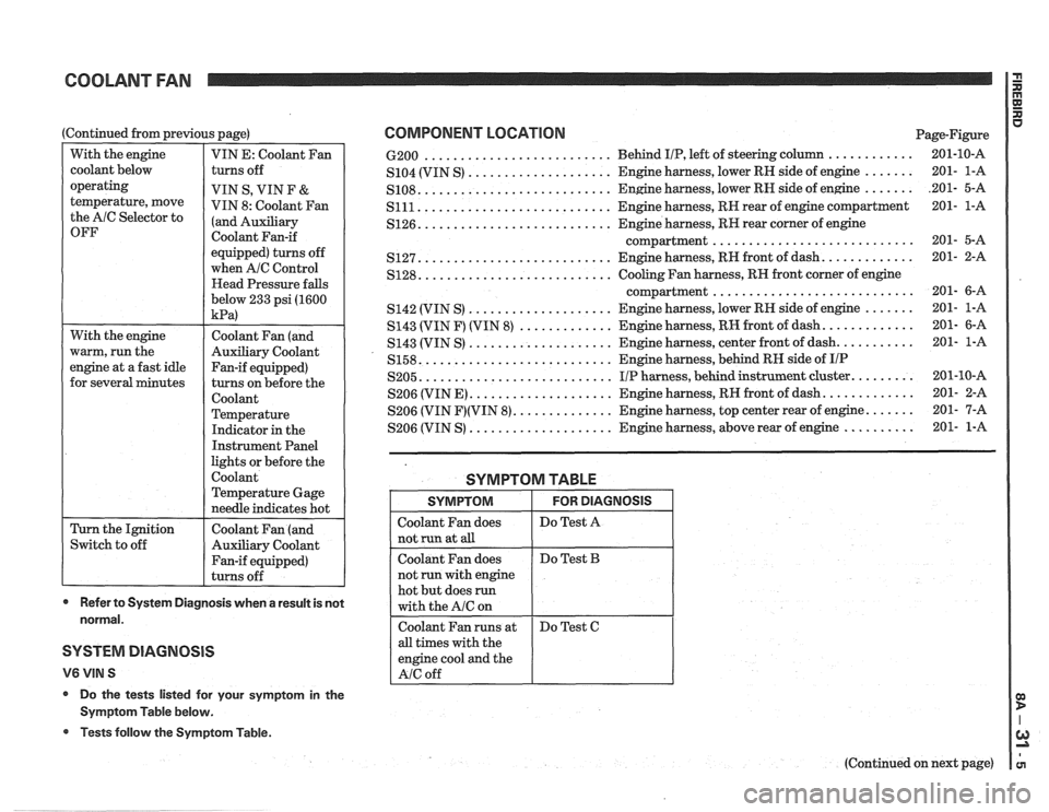
COOLANT FAN
With the engine
warm, run the
engine at a fast idle
for several minutes
(Continued
from previous page)
Switch to off
With
the engine
coolant below
operating
temperature, move
the AlC Selector to
OFF
Coolant Fan (and
Auxiliary Coolant
Fan-if equipped)
turns on before the
Coolant
Temperature
Indicator in the
Instrument Panel
lights or before the
Coolant
Temperature Gage
needle indicates hot
Coolant Fan (and
Auxiliary Coolant
Fan-if equipped)
turns off
VIN E:
Coolant Fan
turns off
VIN S, VIN F
&
VIN 8: coolant Fan
(and ~~~ili~~~
Coolant Fan-if
equipped) turns off
when
A/C Control
Head Pressure falls
below 233 psi (1600
kPa)
- -
* Refer to System Diagnosis when a result is not
normal.
SYSTEM DIAGNOSIS
V6 VIN S
* Do the tests listed for your symptom in the
Symptom Table below.
@ Tests follow the Symptom Table.
COMPONENT LOCATION Page-Figure
.......................... ............ 6-200 Behind IIP, left of steering column 201-10-A
....... .................... S104 (VIN S) Engine harness,
lower RN side of engine 201- l-A
....... .......................... S108. Engine harness, lower RN side of engine .201- 5-A
........................... S111 Engine harness, RR rear of engine compartment 201- l-A
.......................... S126. Engine harness, RR rear corner of engine
............................ compartment 201- 5-A
.......................... ............ S127. Engine harness, RH front of dash. 201- 2-A
.......................... S128. Cooling Fan harness, RN front corner of engine
............................ compartment 201- 6-A
.................... S142 (VIN S) Engine harness, lower RR side of engine ....... 201- l-A
............ S143 (VIN F) (VIN 8) ............. Engine harness, RH front of dash. 201- 6-A
.................... S143 (VIN S) Engine
harness, center front of dash. .......... 201- l-A
.......................... S158. Engine harness, behind RH side of IIP
.......................... S205. I/P harness, behind instrument cluster. ........ 201-10-A
S206 (VIN E)
.................... Engine harness, RH front of dash. ............ 201- 2-A
S206 (VIN
F)(VIN 8). ............. Engine harness, top center rear of engine. ...... 201- 7-A
.................... S206 (VIN S) Engine harness, above rear of engine .......... 201- 1-A
SYMPTOM TABLE
all times with the
engine cool and the
SYMPTOM
Coolant Fan does
not
run at all
Coolant Fan does
not run with engine
hot but does
run
with the A/C on
(Continued on next page)
FOR DIAGNOSIS
Do Test A
Do Test B