1988 PONTIAC FIERO lights
[x] Cancel search: lightsPage 1171 of 1825
INTRODUCTION
COMPONENT LOCATIONS
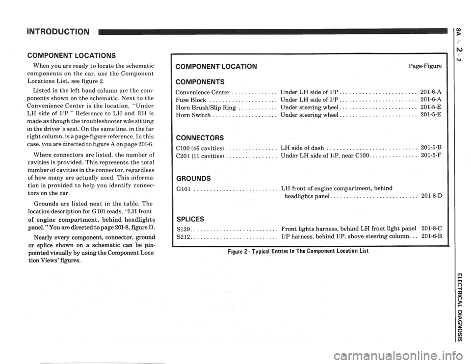
When you are ready to locate the schematic
components on the car, use the Component
Locations List, see figure 2.
Listed in the left hand column are the com-
ponents shown on the schematic. Next to the
Convenience Center is the location, "Under
LH side of
I/P." Reference to LH and RH is
made as though the troubleshooter
was sitting
in the driver's seat. On the same line, in the far
right column, is a page-figure reference. In this
case, you are directed to figure
A on page 201-6.
Where connectors are listed, the number of
cavities is provided. This represents the total
number of cavities in the connector, regardless
of how many are actually used. This informa-
tion is provided to help you identify connec-
tors on the car.
Grounds are listed next in the table. The
location description for
GlOl reads, "LH front
of engine compartment, behind headlights
panel. "You are directed to page 201-8, figure D.
Nearly every component, connector, ground
or splice shown on a schematic can be pin-
pointed visually by using the Component Loca-
tion Views' figures.
COMPONENT LOCATION Page-Figure
COMPONENTS
........................ Convenience Center .............. Under LH side of IIP 201-6-A
..................... ........................ Fuse Block Under LH side of IIP 201-6-A
....................... Horn BrushISlip Ring ............ Under steering wheel. 201-5-E
....................... Horn
Switch .................... Under steering wheel. 201-5-E
CONNECTORS
............................ ................ ClOO (46 cavities)
LH side of dash 201-5-B
................ .............. C201 (11 cavities) Under
LH side of IIP, near C100. 201-5-F
GROUNDS
.......................... GlOl LH front of engine compartment, behind
.......................... headlights panel. 201-8-D
SPLICES
.......................... S139. Front lights harness, behind LH front light panel 201-8-C
.......................... S212. IIP harness, behind IIP, above steering column. .. 201-6-B
Figure 2 - Typical Entries In The Component Location List
Page 1175 of 1825
INTRODUCTION
Fuse Block Details
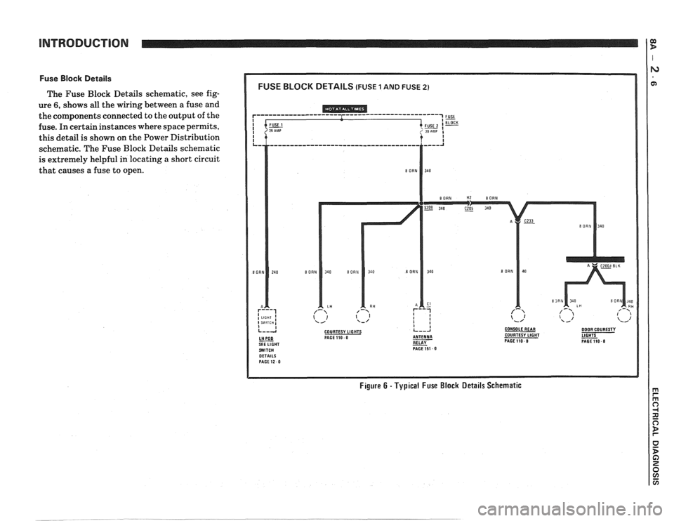
The Fuse Block Details schematic, see fig-
ure
6, shows all the wiring between a fuse and
the components connected to the output of the
fuse. In certain instances where space permits,
this detail is shown on the Power Distribution
schematic. The Fuse Block Details schematic
is extremely helpful in locating
a short circuit
that causes a fuse to open.
COURTESY LIGHTS CONSOLEREAR DOOR COURESTY PAGE110 0 COURTESY LIGHT
RELAY - PAGEllO 0 PAGE151 0
Figure 6 - Typical Fuse Block Details Schematic
Page 1177 of 1825
Ground Distribution
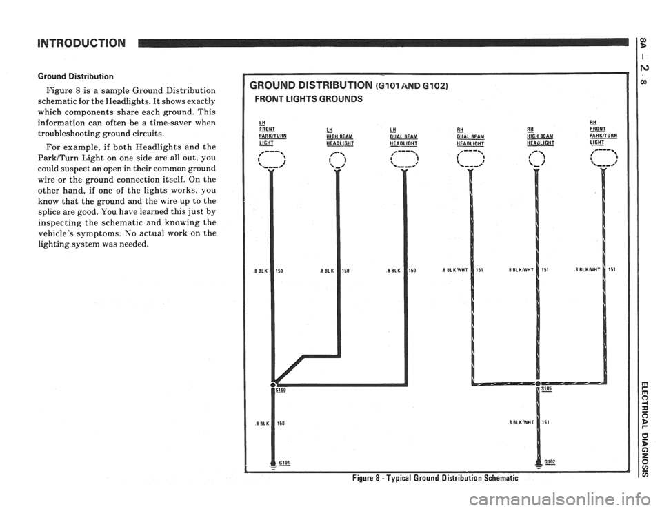
Figure 8 is a sample Ground Distribution
schematic for the Headlights. It shows exactly
which compcments share each ground. This
information can often be a time-saver when
troubleshooting ground circuits.
For example, if both Headlights and the
ParkITurn Light on one side are all out, you
could suspect an open in their common ground
wire or the ground connection itself. On the
other hand, if one of the lights works, you
know that the ground and the wire up to the
splice are good. You
have learned this just by
inspecting the schematic and knowing the
vehicle's symptoms. No actual work on the
lighting system was needed.
GROUND DlSTRlBUTlON (GI01 AND 6102)
FRONT LIGHTS GROUNDS
LH HlGH BEAM LH - DUAL
BEAM
LIGHT - HEADLIGHT HEADLIGHT RH
- DUAL
BEAM
HEADLIGHT E!! &T HIGH BEAM PARKiTURN HEAilLlGHT 1-
Figure 8 - Typical Ground Distribution Schematic
Page 1178 of 1825
ENTIRE
COMPONENT
SHOWN
PART OF A
COMPONENT
SHOWN
NAME OF
COMPONENT
OPERATION COMPONENT
CASE IS
DIRECTLY ATTACHEOTO
- METAL PART
OF CAR
(GROUNOEO)
I FEMALE TERMINAL
CONNECTOR REFERENCE
NUMBER FOR COMPONENT
C103 LOCATION TABLE
7
TABLE ALSO SHOWS
TOTAL NUMBER OF
MALE TERMINAL TERMINALS POSSIBLE: C103 (6 CAVITIES)
/' 5 CAVITY
CONNECTOR
(5 OUT OF 5 CAVITIES
ARE USED)
WlRE IS ATTACHED TO
METAL PART OF CAR
(GROUNOEO)
GROUNO
IS NUMBEREO
GI03 FOR REFERENCE ON - - - COMPONENT LOCATION TABLE
WlRE
IS INOIRECTLY CONNECTED TO GROUNO
SEE GROUNO
OlSTRlBUTlON WlRE MAY HAVE ONE
OR MORE SPLICES
BEFORE IT
IS GROUNOEO
- Gl 01 --
/ 3 5 CAVITY
CONNECTOR
(4 OUT OF 5 CAVITIES
ARE USED)
CONNECTOR
ATTACHEOTO
COMPONENT
CONNECTOR ON
COMPONENT
LEA0 (PIGTAIL) INSULATION
COLOR
IS BOTH
SHOWN AN0 LABELEO
SPLICES ARE SHOWN
AN0 NUMBEREO
CIRCUIT NUMBER
IS SHOWN TO HELP IN
TRACING CIRCUITS
A WAVY
LINE MEANS A WlRE IS TO BE CONTINUED
WlRE INSULATION
2 REOIYEL IS ONE COLOR WlTH ANOTHER 79 COLOR STRIPE (RE0 WlTH YELLOW)
% WIRESIZE AN0 INSULATION
COLOR ARE
LABELEO
CURRENT PATH
IS CONTINUED
AS LABELEO.
THE ARROW SHOWS
THE DIRECTION OF
CURRENT FLOW
TO
AN0 IS REPEATED GENERATOR WHERE CURRENT
PAGE 30-0 PATH CONTINUES.
A WlRE WHICH CONNECTS
TO ANOTHER CIRCUIT.
THEWIRE ISSHOWN AGAIN ON THAT CIRCUIT.
LIGHTS TURNIHAZAROISTOP
Page 1181 of 1825
TROUBLESHOOTING PROCEDURES
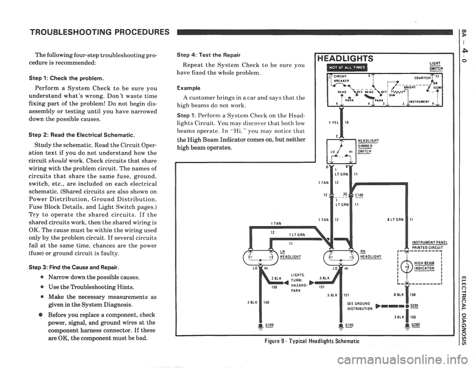
The following four-step troubleshooting pro-
cedure is recommended:
Step 1: Check the problem.
Perform a System Check to be sure you
understand what's wrong. Don't waste time
fixing part of the problem! Do not begin dis-
assembly or testing until you have narrowed
down the possible causes.
Step 2: Read the Electrical Schematic.
Study the schematic. Read the Circuit Oper-
ation text if you do not understand how the
circuit
should work. Check circuits that share
wiring with the problem circuit. The names of
circuits that share the same fuse, ground,
switch, etc., are included on each electrical
schematic. (Shared circuits are also shown on
Power Distribution, Ground Distribution,
Fuse Block Details, and Light Switch pages.)
Try to operate the shared circuits. If the
shared circuits work, then the shared wiring is
OK. The cause must be within the wiring used
only by the problem circuit. If several circuits
fail at the same time, chances are the power
(fuse) or ground circuit is faulty.
Step 3: Find the Cause and Repair.
* Narrow down the possible causes.
@ Use the Troubleshooting Hints.
@ Make the necessary measurements as
given in the System Diagnosis.
Step 4: Test the Repair
Repeat the System Check to be sure you
have fixed the whole problem.
Example
A customer brings in a car and says that the
high beams do not work.
Step 1: Perform a System Check on the Head-
lights Circuit. You may discover that both low
beams operate. In
"Hi," you may notice that
the High Beam Indicator comes on, but neither
high beam operates.
INSTRUMENT PANEL PRINTED CIRCUIT
DISTRIBUTION
@ Before you replace a component, check
power, signal, and ground wires at the
component harness connector. If these
are
OK, the component must be bad. Figure 9 - Typical Headlights Schematic
Page 1182 of 1825
TROUBLESHOOTING PROCEDURES
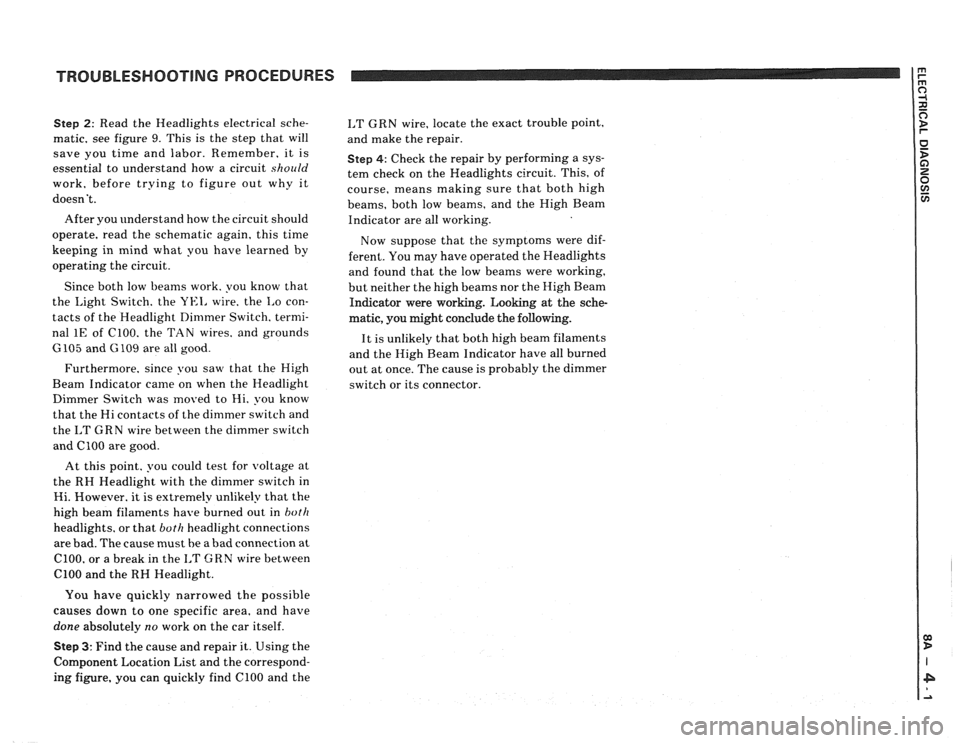
Step 2: Read the Headlights electrical sche-
matic, see figure
9. This is the step that will
save you time and labor. Remember, it is
essential to understand how a circuit
should
work, before trying to figure out why it
doesn't.
After you understand how the circuit should
operate, read the schematic again, this time
keeping in mind what you have learned by
operating the circuit.
Since both low beams work. you know that
the
Light Switch. the YEI, wire. the I,o con-
tacts of the Headlight Dimmer Switch. termi-
nal
1E of C100. the TAN wires. and grounds
6105 and G 109 are all good.
Furthermore, since you saw that the High
Beam Indicator came on when the Headlight
Dimmer Switch was moved to Hi. you know
that the Hi contacts of the
dimmer switch and
the
I,T GRN wire between the dimmer switch
and ClOO are good.
At this point. you could test for
voltage at
the RH Headlight with the dimmer switch in
Hi. However. it is extremely unlikely that the
high beam filaments have burned out in
both
headlights. or that both headlight connections
are bad. The cause must be a bad connection at
C100, or a break in the I,T GRN wire between
ClOO and the RH Headlight.
I,T GRN wire, locate the exact trouble point,
and make the repair.
Step 4: Check the repair by performing a sys-
tem check on the Headlights circuit. This, of
course, means making sure that both high
beams, both low beams, and the High Beam
Indicator are all working.
Now suppose that the symptoms were dif-
ferent. You may have operated the Headlights
and found that the low beams were working,
but neither the high beams nor the High Beam
Indicator were working. Looking at the sche-
matic, you might conclude the
following.
It is unlikely that both high beam filaments
and the High Beam Indicator have all burned
out at once. The cause is probably the dimmer
switch or its connector.
You have quickly narrowed the possible
causes down to one specific area, and have
done absolutely
no work on the car itself.
Step 3: Find the cause and repair it. Using the
Component Location List and the correspond-
ing figure. you can quickly find ClOO and the
Page 1184 of 1825
TROUBLESHOOTING TOOLS TROUBLESHOOTING TESTS
FUSED JUMPER WIRE
A fused jumper is available (5-36169 or equiv-
alent) with small clamp connectors providing
adaptation to most connectors without
damage. This fused jumper wire is supplied
with a
20 amp fuse which may not be suitable
for some circuits. Do not use a fuse with a
higher rating than the fuse that protects the
circuit being tested.
CAUTION: Do not use fused jumper wire
in any instance to substitute for inputs or
outputs at the ECM (Electronic Control
Module), BCM (Body Control Module), or
any microprocessor device.
SHORT FINDER
Short Finders are available (5-8681 or equiv-
alent) to locate hidden shorts to ground. The
short finder creates a pulsing magnetic field in
the shorted circuit and shows you the location
of the short through body trim or sheet metal.
FUSE TESTER
A simple tester that indicates a blown fuse is
available (5-34764 or equivalent). To check a
fuse the tester
is applied directly to the fuse in
the fuse block. Two probes contact the fuse. The
probes are either placed into the slots of a flat
fuse or to the metal ends of a glass fuse. With
power on, a red
LED in the tester lights if the
fuse is open. The handle of the tester is a tool for
removing either type of fuse.
TROUBLESHOOTING TESTS
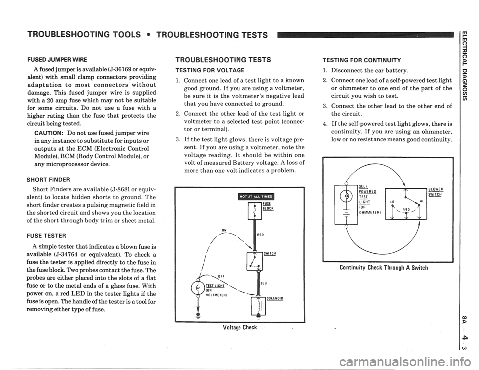
TESTING FOR VOLTAGE
1. Connect one lead of a test light to a known
good ground. If you are using a voltmeter,
be sure it is the voltmeter's negative lead
that you have connected to ground.
2. Connect the other lead of the test light or
voltmeter to a selected test point (connec-
tor or terminal).
3. If the test light glows, there is voltage pre-
sent. If you are using a voltmeter, note the
voltage reading. It should be within one
volt of measured Battery voltage.
A loss of
more than one volt indicates a problem.
Voltage Check .
TESTING FOR CONTINUITY
1. Disconnect the car battery.
2. Connect one lead of a self-powered test light
or ohmmeter to one end of the part of the
circuit you wish to test.
3. Connect the other lead to the other end of
the circuit.
4. If the self-powered test light glows, there is
continuity. If you are using an ohmmeter,
low or no resistance means good continuity.
Continuity Check Through A Switch
Page 1211 of 1825
POWER DISTRIBUTION
COMPONENT LOCATlON Page-Figure
Fusible Link A (VIN S)
............ Lower RH side of engine. at Starter Solenoid ....
Fusible Link B (VIN E) ............ Lower RH side of engine. at Starter Solenoid ....
Fusible Link B (VIN F) (VIN 8) ..... Lower RH side of engine. at Starter Solenoid ....
............ Fusible Link B (VIN S) Lower
RH side of engine. at Starter Solenoid ....
Fusible Link D .................. Front lights harness. near LH side of dash ......
Fusible Link E ................... Front lights harness. near LH side of dash ......
Fusible Link G .................. Front lights harness. near LH side of dash ......
Fusible Link H (VIN E) ........... RH front of engine compartment. at Junction
Block
...................................
Fusible Link N (VIN F) (VIN 8) ..... LN front of engine compartment. behind battery
Fusible Link H (VIN S)
............ Lower RH side of engine. at Starter Solenoid ....
J (VIN E) ............ Lower RH side of engine, at Starter Solenoid ....
J (VIN F) (VIN 8) ..... Lower RH side of engine, at Starter Solenoid ....
J (VIN S) ............ RH side of radiator support. at Junction Block ..
.................. Fusible Link K RN front of engine compartment. at Junction
Block
...................................
Gear Selector Switch ............. In console, at base of gear selector ............
Hatch Fuse ..................... Attached to side of Fuse Block
Hatch Pull-Down Unit
............ Center of end panel, in cargo compartment .....
Headlight Door Module ........... LH front of dash ...........................
Ignition Coil (VIN S) .............. Rear RH side of engine ......................
Ignition Switch .................. Behind IIP. on top side of steering column ......
In-Line Fuse (VIN F)(VIN 8) ....... On LH side of radiator support. forward of
................................. battery
.................. Junction Block RH front of engine compartment. behind
................................ headlight
Lights Monitoring Module
......... Behind IIP. at base of steering column
Mass Air Flow (MAF) Relay (VIN
F)
........................ (VIN 8) LH rear corner of engine compartment, on relay
................................. bracket
Mass Air Flow (MAF) Relay (VIN S)
. Front of engine compartment. on RH side of
radiator bracket
..........................
Mass Air Flow In-Line Fuse ........ RN side of engine compartment, on inner fender
panel
...................................
Remote Dimmer ................. RH side of steering column. on IIP retainer .....
Starter Solenoid (VIN E) .......... Lower RH side of engine ....................
Starter Solenoid (VIN F) (VIN 8) .... Lower RH side of engine ....................