1988 PONTIAC FIERO lights
[x] Cancel search: lightsPage 460 of 1825
CRANKING SYSTEM BD2-9
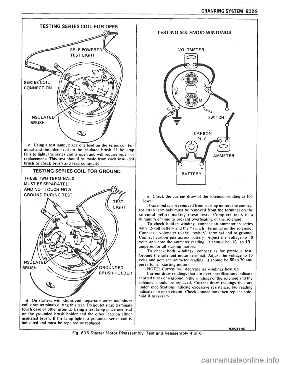
I TESTING SERIES COIL FOR OPEN I
TESTING SOLENOID WINDINGS
c. Us~ng a test lamp. place onelead on the series coil ter-
minal and the other lead on the insulated brush. If the lamp
fails to light. the series coil is open and will require repair or
replacement. This test should be made from each insulated
brush to check brush and lead continuity.
TESTING SERIES COlL FOR GROUND
THESE TWO TERMINALS
MUST BE SEPARATED
d. On starters
withshunt coil. sepanate series and shunt
coil strap terminals during this test. Do not let strap terminals
touch case or other ground. Using a test lamp place one lead
on
he grounded brush holder and the other lead on either
insulated brush. If the lamp lights, a grounded series coil is
indicated and must be repaired or replaced. VOLTMETER
e. Check the current draw of the solenoid winding as fol-
lows:
If solenoid is not removed from starting motor. the connec-
tor
strap terminals must be removed from the terminal on the
solenoid before making these tests. Complete tests in a
minimum of time to prevent overheating of the solenoid.
To check hold-in winding, connect an ammeter in series
with 12-volt battery and the "switch" terminal on the solenoid.
Connect a voltmeter to the "switch" terminal and to ground.
Connect carbon pile across battery. Adjust the voltage to
10 volts and note the ammeter reading. It should be 13 to 19 amperes for all starting motors.
To check both windings. connect as for previous test.
Ground the solenoid motor terminal. Adjust the voltage to 10
volts and note the ammeter reading. It should be
59 to 79 am-
peres for all starting motors.
NOTE: Current will decrease as windings heat up.
Current draw readings that are over specifications indicate
shorted turns or a ground in the windings of the solenoid and the
solenoid should be replaced. Current draw readings that are
under specifications indicate excessive resistance. No reading
indicates an open circuit. Check connections then replace sole-
noid if necessary.
H20255.6D
Fig. 606 Starter Motor Disassembly, Test and Reassembly 4 of 6
Page 464 of 1825
CHARGING SYSTEM 6D3-1
SECTION 6D3
CHARG NG SYSTEM
CONTENTS
General Description ................................. 6D3- 1 Charging System ........................................ 6D3- 1
.......................................... Charging System - CS ............................... 6D3- 1 On-Car Service 6D3-2
................................................... Diagnosis .. 6D3- 1 Generator 6D3-3 ...................... ......................... ............................................. 6D3- 1 Specifications 6D3-3 Service Procedures .................................. Unit Repair .. 6D3-4-6 ............................... ............
GENERAL DESCRIPTION
The engine electrical system includes the battery,
ignition (primary and secondary), starter (and related
wiring) and the generator (and related wiring).
Diagnostic charts (see Section 6D) will aid in
trouble-shooting system faults. When a fault is traced
to a particular component, refer to that components'
section of the service manual.
CHARGING SYSTEM-CS
The CS Charging System has several sizes
available, including the CS-130 and CS-144. The
number (130 or 144) denotes the
OD in mm of the
stator laminations.
CS generators use a new type regulator and a
diode trio is not used. A delta stator, rectifier bridge,
and rotor with slip rings and brushes are electrically
similar to earlier generators. A conventional pulley and
fan is used and, on the CS-130, an internal fan cools the
slip ring end frame, rectifier bridge and regulator.
Unlike three-wire generators, the CS-130 and
CS-144 may be used with only two connections
-
battery positive and an "L" terminal to the charge
indicator bulb. Use of "P",
"F", and "S" terminals is
optional. The "P" terminal is connected to the stator,
and may be connected externally to
a tachometer or other
device. The
"F" terminal is connected internally
to field positive, and may be used as a fault indicator.
The "S" terminal may be connected externally to a
voltage, such as battery voltage, to sense voltage to be
controlled.
As on other charging systems, the charge
indicator lights when the switch is closed, and goes out
when the engine is running. If the charge indicator is
on with the engine running, a charging system defect
is indicated. For all kinds of defects, the indicator will
glow at full brilliance, not "half lit". Also, the charge
indicator will be on with the engine running if system
voltage is too high or too low. The regulator voltage
setting varies with temperature, and limits system
voltage by controlling rotor field current.
This regulator switches rotor field current on and
off at a fixed frequency of about 400 cycles per second.
By varying the on-off time, correct average field
current for proper system voltage control is obtained.
At high speeds, the on-time may be 10% and the
off-time 90%. At low speeds, with high electrical loads,
on-off time may be 90% and
lo%, respectively.
No periodic maintenance on the generator is
required.
DIAGNOSIS
SERVICE PROCEDURES
CHARGING SYSTEM
The generator does not require periodic
lubrication. The rotor shaft is mounted on ball bearings
at the drive end and roller bearings at the slip ring end.
Each contains a permanent grease supply. At periodic
intervals, check mounting bolts for tightness and adjust
belt tension (see Section
6B), if applicable.
e When adjusting belt tension, apply pressure at
center of generator, never against either end
frame.
GENERATOR BENCH CHECK-CS
To check generator in a test stand, remove as
specified in On-Car Service and proceed as follows: 1.
Make connections as shown in Figure
lH, except
leave the carbon pile disconnected. The ground
polarity of generator and battery must be the
same. The battery must be fully charged. Use a
30-500
OHM resistor between battery and "L"
terminal.
2. Slowly increase generator speed and observe
voltage.
3. If the voltage is uncontrolled and increases above
16.0 volts, the rotor field is shorted, the regulator
is defective, or both.
A shorted rotor field coil can
cause the regulator to become defective. NOTE:
The battery must be fully charged when making
this test.
Page 483 of 1825
8B-2 ENGINE ELECTRICAL
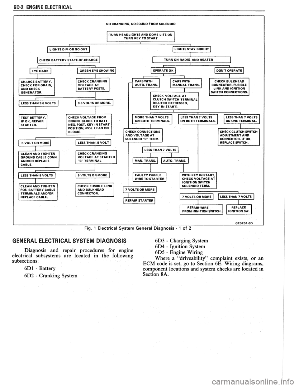
NO CRANKING, NO SOUND FROM SOLENOID
I TURN HEADLIGHTS AND DME LITE ON
TURN KEY TO START I
TEST BETTERY.
IF OK. REPAIR
.5 VOLT OR MORE a
OSITION, (POS. LEAD 0
GROUND CABLE CONN. ANDlOR REPLACE
CABLE.
CLEAN AND TIGHTEN
POS. BATTERY CABLE
TERMINALS
ANDlOR REPLACE CABLE. CONNECTOR.
FUSIBLE
CHECK CONNECTIONS
AND VOLTAGE AT
SOLENOID
"S' TERM.
LESS THAN
7 VOLTS b
FAULTY PURPLE WITH KEY IN START,
WIRE TO STARTER CHECK
VOLTAGE AT
G20201-6D
Fig. 1 Electrical System General Diagnosis - 1 of 2
GENERAL ELECTRICAL SYSTEM DIAGNOSIS 6D3 - Charging System
6D4
- ~~nitcon-§~stem Diagnosis and repair procedures for engine
6D5 - Engine Wiring
electrical subsystems are located in the following
subsections: Where a
"driveability" complaint
exists, or an
ECM code is set, go to Section
6E. Wiring diagrams,
6D
1 - Battery component locations and system checks are located in
6D2
- Cranking System Section 8A.
Page 490 of 1825
DRIVEABILITY AND EMISSIONS 5.OL (VIN E) 6E2-5
ALL NEW GENERAL MOTORS VEHICLES ARE CERTIFIED BY THE UNITED STATES
ENVIRONMENTAL PROTECTION AGENCY AS CONFORMING TO THE REQUIREMENTS OF THE
REGULATIONS FOR THE CONTROL OF AIR POLLUTION FROM NEW MOTOR VEHICLES.
THlS
CERTIFICATION IS CONTINGENT ON CERTAIN ADJUSTMENTS BEING SET TO FACTORY
STANDARDS. IN MOST CASES, THESE ADJUSTMENT POINTS EITHER HAVE BEEN
PERMANENTLY SEALED
AND/OR MADE INACCESSIBLE TO PREVENT INDISCRIMINATE OR
ROUTINE ADJUSTMENT IN THE FIELD. FOR
THlS REASON, THE FACTORY PROCEDURE FOR
TEMPORARILY REMOVING PLUGS, CAPS, ETC., FOR PURPOSES OF SERVICING THE PRODUCT,
MUST BE STRICTLY FOLLOWED AND, WHEREVER PRACTICABLE, RETURNED TO
THE
ORIGINAL INTENT OF THE DESIGN.
INTRODUCTION
GENERAL DESCRIPTION DIAGNOSIS PROCEDURE
This section applies to engines which have a fuel
injector mounted above a throttle body assembly. The
entire assembly is mounted to the intake manifold and
is referred to as "Throttle Body Injection".
These engines have controls to reduce exhaust
emissions, while maintaining good driveability and
fuel economy.
An engine control module
(ECM) is the heart of
this control system and has sensors used to provide
information about engine operation and the various
systems it controls. Details of basic operation,
diagnosis, functional checks, and on-vehicle service
are covered in Section
"C", Component Systems.
The
ECM has the ability to do some diagnosis of
itself, and of other parts of the system. When it finds a
problem,
it lights a "Service Engine Soon" light on the
instrument panel and a trouble code will be stored in
the ECM memory. This does not mean that the engine
should be stopped right away, but that the cause of the
light coming
"ON" should be checked as soon as
reasonably possible. The
following
sectionds) are written for specific
engine applications and are clearly indentified. Be
sure to use only the section which applies to the
engine family being diagnosed.
Before using this section of the manual, you
should be familiar with the information and the
proper diagnosing procedures as described in Section
"6E". If the proper diagnosis procedures are not
follo\l;red, as described in Section "6En, it may result in
unnecessary replacement of good parts.
Trouble tree charts incorporate diagnosis
procedures using an
ALDI, "Scan" tool, where
possible. The "Scan" tool has the ability to save time
in diagnosis and prevent the replacement of good
parts. The key to using; the "Scan" tool
successfully for diagnosis lies in the technician's
abilitv to understand the system
he is try in^ to
diagnose,
as well as an understanding of the
"Scan" tool's limitations. See Section
6E for more
information.
Page 501 of 1825

6EZ-A-10 5.0L (VIN E) DRIVEABILITY AND EMISSIONS
TO OIL PRESS. SW.
&FUEL PUMP RELAY
BATTERY
12 V
. . . . . . . . FUSIBLE LINK 15 WAY
439 PNWBLK
419
BRNNVHT
SERIAL DATA
451
WHTIBLK
450 BLWHT
ALDL CONNECTOR
NO "SERVICE ENGINE SOON" "LIGHT
5.OL (VIN E) "F'" SERIES (TBI)
Circuit Description:
There should always be a steady "Service Engine Soon" light, when the ignition is "ON" and engine stopped.
Battery is supplied directly to the light bulb.
The electronic control module (ECM) will control the light and
turn it "ON" by providing a ground path through CKT 419 to the ECM.
Test Description: Numbers below refer to circled
numbers on the diagnostic chart.
1. Battery feed CKT 340 is protected by a
20amp in-
line fuse. If this fuse was blown, refer to wiring
diagram on the facing page of Code 54.
2. Using a test light connected to 12 volts, probe each
of the system ground circuits to be sure
a good
ground is present. See ECM terminal end view in
front of this section for ECM pin locations of
ground circuits.
Diagnostic Aids:
Engine runs ok, check:
@ Faulty light bulb
@ CKT419open
@ Gage fuse blown. This will result in no oil, or
generator lights, seat belt reminder, etc.
Engine cranks, but will not run.
@ Continuous battery - fuse or fusible link open.
@ ECM ignition fuse open.
@ Battery CKT 340 to ECM open.
o Ignition CKT 439 to ECM open.
@ Poor connection to ECM.
Page 549 of 1825
6EZ-B-2 5.OL (VIN E) DRIVEABILITY AND EMISSIONS
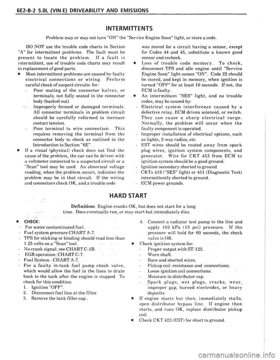
Problem may or may not turn "ON" the "Service Engine Soon" light, or store a code.
DO NOT use the trouble code charts in Section
"A" for intermittent problems. The fault must be
present to locate the problem. If a fault is
intermittent, use of trouble code charts may result
in replacement of good parts.
@ Most intermittent problems are caused by faulty
electrical connections or wiring. Perform
careful check of suspect circuits for:
- Poor mating of the connector halves, or
terminals, not fully seated in the connector
body (backed out).
I - Improperly formed or damaged terminals.
All connector terminals in problem circuit
should be carefully reformed to increase
contact tension.
- Poor terminal to wire connection. This
requires removing the terminal from the
connector body to check as outlined in the
Introduction to Section
"6E".
@ If a visual (physical) check does not find the
cause of the problem, the car can be driven with
a voltmeter connected to a suspected circuit or a
"Scan" tool may be used. An abnormal voltage
reading, when the problem occurs, indicates the
problem may be in that circuit. If the wiring
and connectors check OK, and a trouble code was
stored for a circuit having a sensor, except
for Codes 44 and 45, substitute a known good
sensor and recheck.
@ Loss of trouble code memory. To check,
disconnect TPS and idle engine until "Service
Engine Soon" light comes
"ON". Code 22 should
be stored, and kept in memory, when ignition is
turned "OFF" for at least 10 seconds. If not, the
ECM
is faulty.
@ An intermittent "SES" light, and no trouble
codes, may be caused by:
- Electrical system interference caused by a
defective relay, ECM driven solenoid, or switch.
They can cause a sharp electrical surge.
Normally, the problem will occur when the
faulty component is operated.
- Improper installation of electrical options, such
as lights, 2-way radios, etc.
- EST wires should be routed away from spark
plug wires, ignition system components, and
generator. Wire for CKT 453 from ECM to
ignition system should be a good ground.
- Ignition secondary shorted to ground.
- CKTs 419 ("SES" light) or 451 (Diagnostic Test)
intermittently shorted to ground.
- ECM power grounds.
HARD START
Definition: Engine cranks OK, but does not start for a long
time. Does eventually run, or may start but immediately dies.
, <
@ CHECK: 4. Connect a radiator test pump to the line and
- For water contaminated fuel. apply 103 kPa (15 psi) pressure. If the
- Fuel system pressure CHART A-7. pressure will hold for 60 seconds, the check
- TPS for sticking or binding should read less than
valve is OK.
1.25 volts on a "Scan" tool. @ Check ignition system for:
- No crank signal; see CHART C-1B. - Proper output with ST-125.
- EGR operation; CHART C-7. - Worn shaft.
- Fuel System - CHART A-7. - Rare and shorted wires.
- For a faulty in-tank fuel pump check valve, - Pickup coil resistance and connections.
which would allow the fuel in the lines to drain
- Loose ignition coil connections.
back to the tank after the engine is stopped. To
- Moisture in distributor cap.
check for this condition:
- Spark plugs, wet plugs, cracks, wear,
1. Ignition "OFF".
improper gap, burned electrodes, or heavy
2. Disconnect fuel line at the filter
deposits.
3. Remove the tank filler cap. @ If engine starts but then, immediately stalls,
open distributor bypass line. If engine then
starts, and runs OK, replace distributor pickup
coil.
@ Check CKT 423 (EST) for short to ground.
Page 653 of 1825
6E3-8 2.8L (VIM $1, 5.OL (VIN F) & 5.7L(VlN 8) BRlVEABILlTY AND EMISSIOMS
ALL NEW GENERAL MOTORS VEHICLES ARE CERTIFIED BY THE UNITED STAEES
ENVIRONMENTAL PROTECTION AGENCY AS CONFOWMlNG TO "THE REQUIREMENTS QF THE
REGULATIONS FOR THE CONTROL OF AIR POLLUTION FROM NEW MOTOR VEHICLES. THIS
CERTlFlCATlON IS CONTINGENT ON CERTAIN ADJUSTMENTS BEING SET TO FACTORY
STANDARDS. IN MOST CASES, THESE ADJUSTMENT POINTS EITHER HAVE BEEN
PERMANENTLY SEALED ANDIOR MADE
INACCESSlBLE TO PREVENT INDISCRIMINATE OR
ROUTINE ADJUSTM&M"FIN THE FIELD. FOR THIS REASON, THE FACTORY PROCEDURE FOR
TEMPORARILY REMOVING PLUGS, CAPS, ETC., FOR PURPOSES OF SERVICING THE PRODUCT,
MUST
BE STRICTLY FOLLOWED AND, WHEREVER PRACTICABLE, RETURNED TO THE
ORIGINAL INTENT QF THE DESIGN.
INTRODUCTION
GENERAL BESCRIPT18N DIAGNOSIS PROCEDURE
This section applies to engines which have a fuel
injector in the intake manifold near the intake valve
for each cylinder. It is commonly referred to as "Port
Fuel Injection".
These engines have controls to reduce exhaust
emissions, while maintaining good driveability and
fuel economy.
An engine control module
(ECM) is the heart of
this control system and has sensors used to provide
information about engine operation and the various
systems it controls. Details of basic operation,
diagnosis, functional checks, and on-vehicle service
are covered in Section "C", "Component Systems".
The ECM has the ability to do some diagnosis of
itself, and of other parts of the system. When it finds a
problem, it lights a "Service Engine Soon" light on the
instrument panel and
a trouble code will be stored in
the ECM memory. This does not mean that the engine
should be stopped right away, but that the cause of the
light coming
"ON" should be checked as soon as
reasonably possible. The
following
sections(s) are written for specific
engine applications and are clearly indentified. Be
sure to use only the section which applies to the
engine family being diagnosed.
Before using this section of the manual, you
should be familiar with the information and the
proper diagnosing procedures as described in Section
"GE". If the proper diagnosis procedures are not
followed, as described in Section
"6EM, it may result in
unnecessary replacement of good parts.
Trouble tree charts incorporate diagnosis
procedures using an ALDL "SCAN" tool where
possible.
The "SCANJ' tool has the ability to save time
in diagnosis and prevent the replacement of good
parts. The
key to using the "SCAN" tool
successfully for diagnosis lies in the technician's
ability to understand the system he is
trving to
diagnose. as well as an understanding of the
"SCAN" tool's limitations. See Section "6E" for
more information.
Page 663 of 1825

6E3-A-"I 2.8L (VlN S) DRIVEABILITY AND EMlSSlONS
TO OIL PRESS. SW.
&FUEL PUMP RELAY
FUSE
81 HOLDER BATTERY 12 V .. m.. . n.
. . . . . . . . FUSIBLE LINK
439 PNWBLK
419 BRNNVHT
SERIAL
DATA
451
WHTJBLK
450 BLKNVHT
ALDL CONNECTOR
NO "SERVICE ENGlNE SOON" "LIGHT
2.8b (VIM 5) 'T" "SERIES (PORT)
Circuit Description:
There should always be a steady "Service Engine Soon" light when the ignition is "ON" and engine stopped.
Battery is supplied directly to the light bulb. The electronic control module
(ECNI) will control the light and
turn it "ON" by providing a ground path through CKT 419 to the ECM.
Test Description: Numbers below refer to circled
numbers on the diagnostic chart.
1. If the fuse in holder is blown refer to facing page of
Code
54 for complete circuit.
2. Using a test light connected to 12 volts probe each
of the system ground circuits to be sure a good
ground is present. See ECM terminal end view in
front of this section for
ECM pin locations of
ground circuits.
Diagnostic Aids:
Engine runs OK, check:
@ Faulty light bulb.
@ CKT 419 open.
@ Gage fuse blown.
This will result in no oil or
generator lights, seat belt reminder, etc. Engine
cranks but will not run.
@ Continuous battery - fuse or fusible link open.
@ ECM ignition fuse open.
@ Battery CKT 340 to ECM open.
@ Ignition CKT 439 to ECM open.
e Poor connection to ECM.
Solenoids and relays are turned "ON"
and "OFF"
by the ECM, using internal electronic switches called
"drivers". Each driver is part of a group of four called
"Quad-Drivers". Failure of one driver can damage
any other driver in the set. Solenoid and relay coil
resistance must measure more than 20 ohms. Less
resistance will cause early failure of the ECM
"driver".
Before replacing ECM, be sure to check the coil
resistance of all solenoids and relays controlled by the
ECM. See ECM wiring diagram for the
solenoid(s)
and relay(s) and the coil terminal identification.