1988 PONTIAC FIERO lights
[x] Cancel search: lightsPage 711 of 1825
6E3-B-2 2.8L (VIN 5) DRIVEABILITY AND EMISSIONS
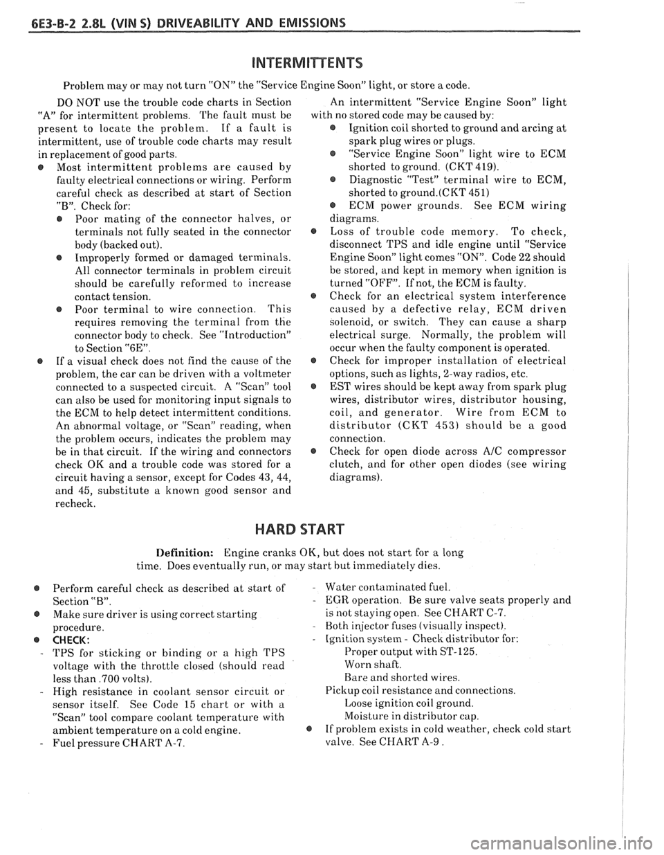
Problem may or may not turn "ON" the "Service Engine SoonJ' light, or store a code.
DO NOT use the trouble code charts in Section
"A" for intermittent problems. The fault must be
present to locate the problem. If a fault is
intermittent, use of trouble code charts may result
in replacement of good parts.
@ Most intermittent problems are caused by
faulty electrical connections or wiring. Perform
careful check as described at start of Section
"B". Check for:
@ Poor mating of the connector halves, or
terminals not fully seated in the connector
body (backed out).
@ Improperly formed or damaged terminals.
All connector terminals in problem circuit
should be carefully reformed to increase
contact tension.
@ Poor terminal to wire connection. This
requires removing the terminal from the
connector body to check. See "Introduction"
to Section
"6E".
@ If a visual check does not find the cause of the
problem, the car can be driven with a voltmeter
connected to a suspected circuit. A "Scan" tool
can also be used for monitoring input signals to
the ECM to help detect intermittent conditions.
An abnormal voltage, or "Scan" reading, when
the problem occurs, indicates the problem may
be in that circuit. If the wiring and connectors
check OK and a trouble code was stored for a
circuit having a sensor, except for Codes
43, 44,
and 45, substitute a known good sensor and
recheck. An
intermittent "Service Engine Soon" light
with no stored code may be caused by:
@ Ignition coil shorted to ground and arcing at
spark plug wires or plugs.
@ "Service Engine Soon" light wire to ECM
shorted to ground. (CKT 419).
@ Diagnostic "Test" terminal wire to ECM,
shorted to
ground.(CKT 451)
@ ECM power grounds. See ECM wiring
diagrams.
@ Loss of trouble code memory. To check,
disconnect TPS and idle engine until "Service
Engine Soon" light comes "ON". Code
22 should
be stored, and kept in memory when ignition is
turned "OFF". If not, the ECM is faulty.
@ Check for an electrical system interference
caused by a defective relay, ECM driven
solenoid, or switch. They can cause
a sharp
electrical surge. Normally, the problem will
occur when the faulty component is operated.
@ Check for improper installation of electrical
options, such as lights, 2-way radios, etc.
@ EST wires should be kept away from spark plug
wires, distributor wires, distributor housing,
coil, and generator. Wire from ECM to
distributor (CKT
453) should be a good
connection.
@ Check for open diode across A/C compressor
clutch, and for other open diodes (see wiring
diagrams).
HARD START
Definition: Engine cranks OK, but does not start for a long
time. Does eventually run, or may start hut immediately dies.
@ Perform careful check as described at start of -
Section "B".
@ Make sure driver is using correct starting
procedure.
@ CHECK:
- TPS for sticking or binding or a high TPS
voltage with the throttle closed (should read
less than
,700 volts).
- High resistance in coolant sensor circuit or
sensor itself. See Code 15 chart or with
a.
"Scan" tool compare coolant temperature with
ambient temperature on
a cold engine. 8
- Fuel pressure CHART A-7. Water contaminated
fuel.
EGR operation. Be sure valve seats properly and
is not staying open. See CHART C-7.
Both injector fuses (visually inspect).
Ignition system
- Check distributor for:
Proper output with ST-125.
Worn shaft.
Bare and shorted wires.
Pickup coil resistance and connections.
Loose ignition coil ground.
Moisture in distributor cap.
If problem exists in cold weather, check cold start
valve. See CHART A-9.
Page 813 of 1825
TO MAF SENSOR
POWER & BURN-OFF
RELAY, OIL PRESS. SW.
.....-
439 PNKIBLK
419 BRNNVHT
SERIAL DATA
451 WHTIBLK
450
BLWHT
ALDL CONNECTOR
CHART A - 1
NO "'SERVICE ENGINE SOON" LIGHT
5.OL (VIN F) & 5.7L (VIN 8) "F'XSEBIE'S (PORT)
Circuit Description:
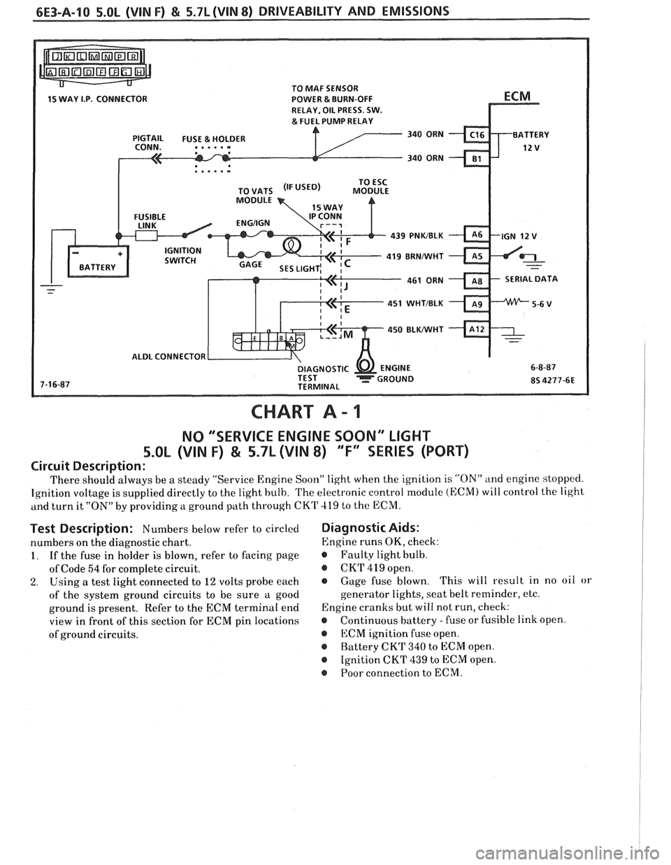
There should always be a steady "Service Engine Soon" light when the ignition is "ON" and engine stoppccl.
Ignition voltage is supplied directly to the light bulb. The electronic control module (ECM) will control the light
and turn it
"ON" by providing a ground path through CKT 419 to the ECM.
Test Description: Numbers below refer to circled
numbers on the diagnostic chart.
1. If the fuse in holder is blown, refer to facing page
of Code
54 for complete circuit.
2. Using a test light connected to 12 volts probe each
of the system ground circuits to be sure a good
ground is present. Refer to the ECM terminal end
view in front of this section for ECM pin locations
of ground circuits.
Diagnostic Aids:
Engine runs OK, check:
r Faulty light bulb.
@ CKrI' 419 open.
@ Gage fuse blown. This
will result in no oil or
generator lights, seat belt reminder, etc.
Engine cranks but will not run, check:
r Continuous battery - fuse or fusible link open.
@ ECM ignition fuse open.
r Battery CKT 340 to ECM open.
@ Ignition CKT 439 to ECM open.
@ Poor connection to ECM.
Page 867 of 1825
6E3-B-2 5.OL (VIN F) & 5.7L (VIN 8) DRIVEABILITY AND EMISSIONS
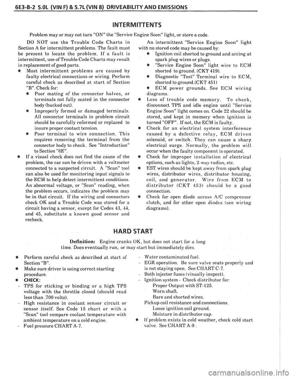
Problem may or may not turn "ON" the "Service Engine Soon" light, or store a code.
DO NOT use the Trouble Code Charts in
An intermittent "Service Engine Soon" light
Section A for intermittent problems. The fault must
with no stored code may be caused by:
be present to locate the problem. If a fault is
@ Ignition coil shorted to ground and arcing at
intermittent, use of Trouble Code Charts
may result
spark plug wires or plugs.
in replacement of good parts.
"Service Engine Soon" light wire to
ECM
@ Most intermittent problems are caused by
shorted to ground. (CKT 419).
faulty electrical connections or wiring. Perform
Diagnostic "Test" Terminal wire to ECM,
careful check as described at start of Section
shorted to
ground.(CKT 451)
"B". Check for:
@ ECM power grounds. See ECSI wiring
@ Poor mating of the connector halves, or diagrams.
terminals not fully seated in the connector
@ Loss of trouble code memory. To check,
body (backed out). disconnect TPS and idle engine until "Service
@ Improperly formed or damaged terminals.
Engine Soon" light comes on. Code 22 should be
All connector terminals in problem circuit
stored, and kept in memory when ignition is
should be carefully reformed or replaced to turned "OFF". If not, the ECM is faulty.
insure proper contact tension.
@ Check for an electrical system interference
@ Poor terminal to wire connection. This caused by a defective relay, ECM driven
requires removing the terminal from the
solenoid, or switch. They can cause a sharp
connector body to check. See "Introduction"
electrical surge. Normally, the problem will
to Section
"6E". occur when the faulty component is operated.
@ If a visual check does not find the cause of the @ Check for improper installation of electrical
problem, the car can be driven with a voltmeter
options, such as lights,
%way radios, etc.
connected to
a suspected circuit. A "Scan" tool
EST wires should be kept away from spark plug
can also be used for monitoring input signals to wires, distributor wires, distributor housing,
the ECM to help detect intermittent conditions. coil, and generator. Wire from
ECM to
An abnormal voltage, or "Scan" reading, when distributor
(CKT 453) should be a good
the problem occurs, indicates the problem
may connection.
be in that circuit. If the wiring and connectors
@ Check for open diode across AIC compressor
check OK and a Trouble Code was stored for a
clutch, and for other open diodes (see wiring
circuit having a sensor, except for Codes
43, 44, diagrams).
and 45, substitute a known good sensor and
recheck.
HARD START
Definition: Engine cranks OK, but does not start for a long
time. Does eventually run, or may start but immediately dies.
Perform careful check as described at start of
Section
"B".
@ Make sure driver is using correct starting
procedure.
@ CHECK:
- TPS for sticking or binding or a high TPS
voltage with the throttle closed (should read
less than
.700 volts).
- High resistance in coolant sensor circuit or
sensor itself. See Code 15 chart or with
a
"Scan" tool compare coolant temperature with
ambient temperature on a cold engine.
- Fuel pressure CHART A-7.
- Water contaminated fuel.
- EGR operation. Be sure valve seats properly and
is not staying open. See CHART C-7.
- Both injector fuses (visually inspect).
- Ignition system - Check distributor for:
Proper Output with ST-125.
Worn shaft.
Bare and shorted wires.
Pickup coil resistance and connections.
Loose ignition coil ground.
Moisture in distributor cap.
@ If problem exists in cold weather, check cold start
valve. See CHART A-9.
Page 975 of 1825
6E-14 DRIVEABILITY AND EMISSIONS - FUEL INJECTION
N.O. - NORMALLY OPEN - State of relay contacts
or solenoid plunger when no voltage
is applied.
NOx - NITROGEN, OXIDES OF - One of the
pollutants found in engine exhaust.
O2 - OXYGEN (Sensor) - Monitors the oxygen
content of the exhaust system and generates a voltage
signal to the ECM.
OIL or OILOOP - OPEN LOOP - Describes ECM fuel
control without use of oxygen sensor information.
OUTPUT - Result of a function typically controlled
by the ECM.
OXYGEN SENSOR. EXHAUST - Device that detects
the amount of oxygen
(02) in the exhaust stream.
P.A.1.R - PULSE AIR INJECTION REACTOR system -
pulsed air directed into engine to reduce exhaust
emissions.
PCV - POSITIVE CRANKCASE VENTILATION -
Prevent fumes in crankcase from passing into
atmosphere.
PFI - PORT FUEL INJECTION
PIN
- PARWNEUTWL
PORT - EXHAUST OR INTAKE PORT
PROM
- PROGRAMABLE READ ONLY MEMORY-
an electronic term used to describe the engine
calibration unit
.
RPM - REVOLUTIONS PER MINUTE - A measure of
rotational speed.
RVB - REAR VACUUM BMKE - is used to control
choke operation during cold engine conditions.
SELF-DIAGNOSTIC CODE - The ECM can detect
malfunctions in the system.
If a malfunction occurs,
the ECM turns on the "Service Engine Soon" light.
A
diagnostic code can be obtained from the ECM
through the "Service Engine Soon" light, or by use of a
"Scan" tool. This code will indicate the area of the
malfunction.
SES - SERVICE ENGINE SOON LIGHT - Lights when
a malfunction occurs in Computer Command Control
system.
TACH - TACHOMETER
TBI
- THROTTLE BODY INJECTION (Unit) - is
controlled by the ECM to supply precise airlfuel
mixture into the intake manifold.
TCC - TWNSMISSION I TRANSAXLE CONVERTER
CLUTCH
- ECM controlled solenoid in transmission
which positively couples the transmission to the
engine.
THERMAC - THERMOSTATIC AIR CLEANER -
provides preheated air to intake manifold to provide
better driveability when engine
is cold.
TPS - THROnLE POSITION SENSOR - Device that
tells the ECM the throttle position.
TVS - THERMAL VACUUM SWITCH - Used to
control vacuum in relationship to engine temperature.
V - VOLT
V-6 - SIX CYLINDER ENGINE - Two banks of
cylinders, arranged in a
"V".
V-8 - EIGHT CYLINDER ENGINE - Two banks of
cylinders, arranged in a
"V".
VACUUM - Negative pressure; less than
atmospheric pressure.
VACUUM, MANIFOLD - Vacuum source in
manifold below throttle plate.
VACUUM, PORTED - A vacuum source above I (atmospheric side ) of closed throttle plate. , I
WAC SENSOR - Abbreviation for differential
pressure sensor which is a
vacuum sensor.
VIN - VEHICLE IDENTIFIUTION NUMBER. 1
VSS - VEHICLE SPEED SENSOR - Sensor which
sends vehicle speed information to the ECM.
WASTECATE - A means of controlling the amount
of boost available for a Turbo charged engine.
WOT- WIDE OPEN THROPTLE. I
WIRING HARNESS SERVICE I
The ECM wire harness electrically connects the
ECM to the various solenoids, switches, and sensors in
vehicle engine compartment. The ECM is located
inside the vehicle passenger compartment.
Most connectors in the engine compartment are
protected against moisture and dirt which could create
oxidation and deposits on the terminals. This
protection is important because of the very low voltage
and current levels found in the electronic system. The
connectors have a lock which secures the male and
female terminals together. A secondary lock holds the
seal and terminal into the connector.
GENERAL
Molded-on connectors (like Metri-Pack) require
complete replacement of the connector. This means
splicing a new connector assembly into the harness.
Page 1166 of 1825
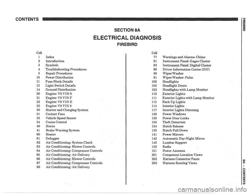
CONTENTS
ELECTRICAL DIAGNOSIS
Cell
1
2
3
4 5
10
11
12 14
20
21
22
23
30
31
33
34
40
4
1
60
61
62
63
64
65
66
67
68
Index
Introduction
Symbols
Troubleshooting Procedures Repair Procedures
Power Distribution
Fuse Block Details
Light Switch Details
Ground Distribution
Engine:
V6 VIN S
Engine: V8 VIN
F
Engine: V8 VIN E
Engine:
V8 VIN 8
Starter and Charging System
Coolant Fans
Vehicle Speed Sensor
Cruise Control Horns
Brake Warning System
Heater
Defogger
Air Conditioning: System Check
Air Conditioning: Blower Controls
Air Conditioning: Compressor Controls
Air Conditioning: Air Delivery
Air Conditioning: Blower Controls
Air Conditioning: Compressor Controls
Air Conditioning: Air Delivery Cell
77
8
1
82
86 90
9
1
100
102
103
110
111
112
114
117
120
130
133
134
135
141
143
145
150
151
201 202
203
Warnings and Alarms: Chime
Instrument Panel: Gages Cluster
Instrument Panel:
Digital Cluster
Driver Information Center
(DIC)
WiperlWasher
WiperlWasher: Pulse
Headlights
Headlight Doors
Headlights with Lamp Monitor
Exterior Lights
Exterior Lights with Lamp Monitor
Back Up Lights
Interior Lights
Interior Lights Dimming
Power Windows
Power Door Locks
Theft Deterrent
Hatch Release
Hatch Pull-Down
Power Mirrors
Automatic Day-Night Mirror
Lumbar Support
Radio Power Antenna
Component Location Views
Harness Connector Faces
Harness Routing Views
Page 1167 of 1825
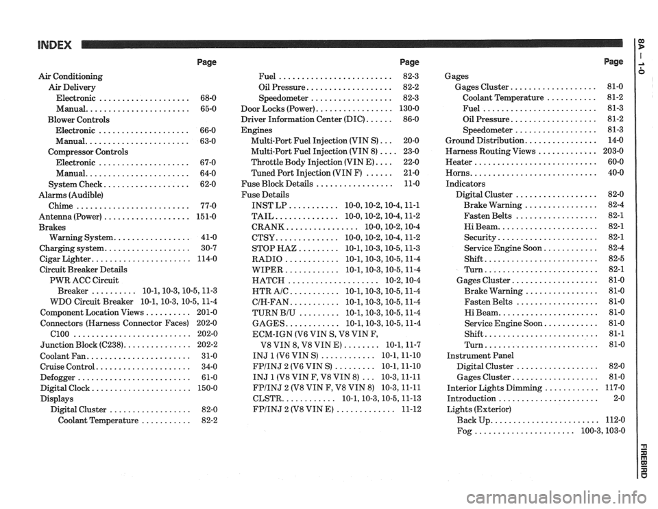
Page
Air Conditioning
Air Delivery
Electronic
.................... 68-0
Manual
....................... 65-0
Blower Controls
Electronic
.................... 66-0
Manual
....................... 63-0
Compressor Controls Electronic
.................... 67-0
Manual
....................... 64-0
................... System Check 62-0
Alarms (Audible)
Chime
......................... 77-0
Antenna(Power) ................... 151-0
Brakes
................. Warning System 41-0
................... Charging system 30-7
...................... Cigar Lighter 114-0
Circuit Breaker Details
PWR ACC Circuit
.......... Breaker 10.1.10.3.10.5.1 1.3
WDO Circuit Breaker
10.1. 10.3. 10.5. 11-4
.......... Component Location Views 201-0
Connectors (Harness Connector Faces) 202-0
el00 .......................... 202-0
............... Junction Block ((2238) 202-2
Coolant Fan
....................... 31-0
Cruise Control
..................... 34-0
Defogger
......................... 61-0
Digital Clock
...................... 150-0
Displays Digital Cluster
.................. 82-0
Coolant Temperature
........... 82-2
Page
......................... Fuel 82-3
................... Oil Pressure 82-2
.................. Speedometer 82-3
................. Door Locks (Power) 130-0
...... Driver Information Center (DIC) 86-0
Engines
... Multi-Port Fuel Injection (VIN S) 20-0
.... Multi-Port Fuel Injection (VIN 8) 23-0
.... Throttle
Body Injection (VIN E) 22-0
...... Tuned
Port Injection (VIN F) 21-0
................. Fuse Block Details 11-0
Fuse Details
........... INST LP 10.0.10.2.10.4.1 1.1
.............. TAIL 10.0.10.2.10.4.1 1.2
................ CRANK 10.0.10.2.1 0.4
.............. CTSY 10~0.10.2.10.4.1 1.2
......... STOP HAZ 10.1.10.3.10.5.1 1.3
............ RADIO 10.1.10.3.10.5.1 1.4
............ WIPER 10.1.10.3.10.5.1 1.4
.................... HATCH 10.2.1 0.4
........... HTR AlC 10.1.10.3.10.5.1 1.4
........... CIH.FAN 10.1.10.3.10.5.1 1.4
......... TURN BIU 10.1.10.3.10.5.1 1.4
............ GAGES 10.1.10.3.10.5.1 1.4
ECM-IGN
(V6 VIN S. V8 VIN F.
........ V8 VIN 8. V8 VIN E) 10.1.1 1.7
............ INJ 1 (V6 VIN S) 10.1.1 1.10
......... FPIINJ 2 (V6 VIN S) 10.1.1 1.10
... INJ 1 (V8 VIN F. V8 VIN 8) 10.3.1 1.11
FPIINJ 2 (V8 VIN F. V8 VIN 8) 10.3.1 1.11
............ CLSTR 10.1.10.3.10.5.1 1.13
............. FPIINJ 2 (V8 VIN E) 11-12
Page
Gages
................... Gages Cluster 81-0
........... Coolant Temperature 81-2
......................... Fuel 81-3
................... Oil Pressure 81-2
.................. Speedometer 81-3
................ Ground Distribution 14-0
Harness Routing Views
............. 203-0
........................... Heater 60-0
............................ Horns 40-0
Indicators
.................. Digital Cluster 82-0
................ Brake Warning 82-4
.................. Fasten Belts 82-1
...................... Hi Beam 82-1
...................... Security 82-1
............ Service Engine Soon 82-4
......................... Shift 82-5
......................... Turn 82-1
................... Gages Cluster 81-0
................ Brake Warning 81-0
.................. Fasten Belts 81-0
...................... Hi Beam 81-0
............ Service Engine Soon 81-0
......................... Shift 81-1
......................... Turn 81-0
Instrument Panel
Digital Cluster
.................. 82-0
Gages Cluster
................... 81-0
............ Interior Lights Dimming 117-0
...................... Introduction 2-0
Lights (Exterior)
........................ Back Up 112-0
...................... Fog 100.3,10 3.0
Page 1168 of 1825
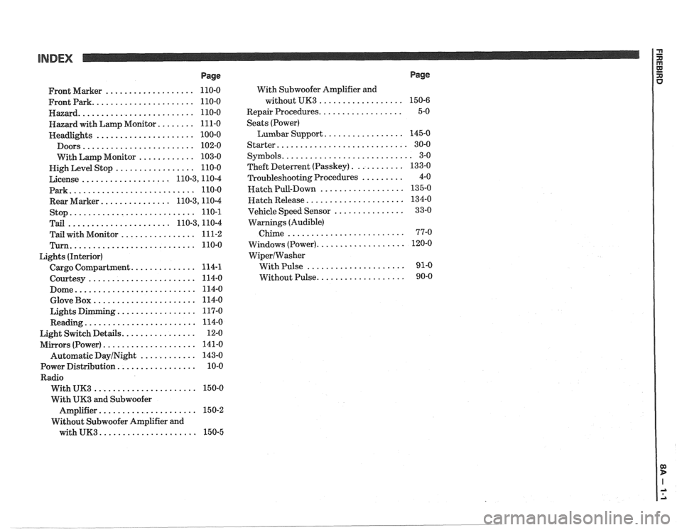
INDEX
Page
................... Front Marker 110-0
...................... Frontpark 110-0
......................... Hazard 110-0
........ Hazard with Lamp Monitor 111-0
..................... Headlights 100-0
........................ Doors 102-0
............ With Lamp Monitor 103-0
................. Nigh Level Stop 110-0
................... License 110.3,11 0.4
Park
........................... 110-0
............... Rear Marker 110.3,11 0.4
stop
........................... 110-1
...................... Tail 110.3,11 0.4
................ Tail with Monitor 111-2
Turn ........................... 110-0
Lights (Interior)
.............. Cargo Compartment 114-1
....................... Courtesy 114-0
.......................... Dome 114-0
...................... Glove Box 114-0
................. Lights Dimming 117-0
........................ Reading 114-0
................ Light Switch Details 12-0
.................... Mirrors (Power) 141-0
Automatic
DayINight ............ 143-0
................. Power Distribution 10-0
Radio
...................... With UK3 150-0
With
UK3 and Subwoofer
..................... Amplifier 15 0-2
Without Subwoofer Amplifier and
with
UK3 ..................... 150-5 With
Subwoofer Amplifier and
without UK3
..................
.................. Repair Procedures
Seats (Power)
Lumbar Support
.................
Starter ............................
........................... Symbols
........... Theft Deterlent (Passkey)
......... Troubleshooting Procedures
.................. Hatch Pull-Down
..................... Hatch Release
............... Vehicle Speed Sensor
Warnings (Audible)
Chime
.........................
................... Windows (Power)
WiperIWasher
With Pulse .....................
................... Without Pulse
Page
Page 1169 of 1825
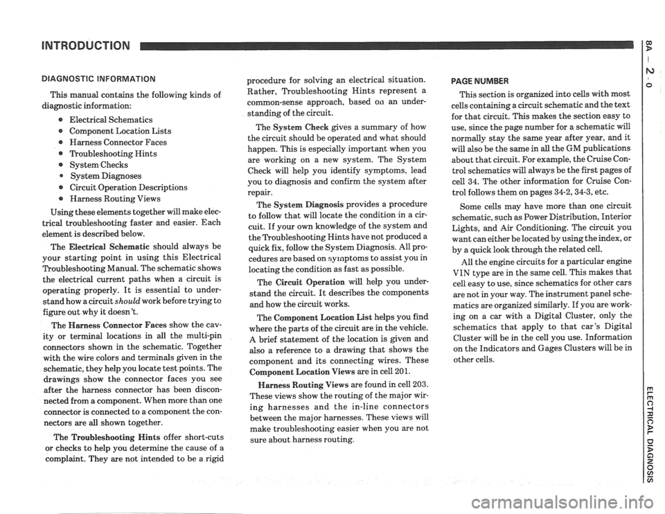
INTRODUCTION 1:
This manual contains the following kinds of
diagnostic information:
e Electrical Schematics
Component Location Lists
@ Harness Connector Faces
@ ?koubleshooting Hints
@ System Checks
System Diagnoses
@ Circuit Operation Descriptions
@ Harness Routing Views
Using these elements together will make elec-
trical troubleshooting faster and easier. Each
element is described below.
The Electrical
Seher~latic should always be
your starting point in using this Electrical
Troubleshooting Manual. The schematic shows
the electrical current paths when a circuit is
operating properly. It is essential to under-
stand how a circuit
should work before trying to
figure out why it doesn't.
The Harness Connector Faces show the cav-
ity or terminal locations in all the multi-pin
connectors shown in the schematic. Together
with the wire colors and terminals given in the
schematic, they help you locate test points. The
drawings show the connector faces you see
after the harness connector has been discon-
nected from a component. When more than one
connector is connected to a component the con-
nectors are all shown together.
The Troubleshooting Hints offer short-cuts
or checks to help you determine the cause of
a
complaint. They are not intended to be a rigid procedure
for solving an electrical situation.
Rather, Troubleshooting Nints represent a
common-sense approach, based on an under-
standing of the circuit.
The System Check gives a summary of how
the circuit should be operated and what should
happen. This is especially important when you
are working on a new system. The System
Check will help you identify symptoms, lead
you to diagnosis and confirm the system after
repair.
The System Diagnosis provides a procedure
to follow that will locate the condition in a cir-
cuit. If your own knowledge of the system and
the Troubleshooting Hints have not produced
a
quick fix, follow the System Diagnosis. All pro-
cedures are based on symptoms to assist you in
locating the condition as fast as possible.
The Circuit Operation will help you under-
stand the circuit. It describes the components
and how the circuit works.
The Component Location List helps you find
where the parts of the circuit are in the vehicle.
A brief statement of the location is given and
also a reference to a drawing that shows the
component and its connecting wires. These
Colnponent Location Views are in cell 201.
Harness Routing Views are found in cell 203.
These views show the routing of the major wir-
ing harnesses and the in-line connectors
between the major harnesses. These views will
make troubleshooting easier when you are not
sure about harness routing.
PAGE NUMBER
This section is organized into cells with most
cells containing a circuit schematic and the text
for that circuit. This makes the section easy to
use, since the page number for a schematic will
normally stay the same year after year, and it
will also be the same in
all the GM publications
about that circuit. For example, the Cruise Con-
trol schematics will always be the first pages of
cell 34. The other information for Cruise Con-
trol follows them on pages
34-2,34-3, etc.
Some cells may have more than one circuit
schematic, such as Power Distribution, Interior
Lights, and Air Conditioning. The circuit you
want can either be located by using the index, or
by a quick look through the related cell.
All the engine circuits for a particular engine
VIN type are in the same cell. This makes that
cell easy to use, since schematics for other cars
are not in your way. The instrument panel sche-
matics are organized similarly. If you are work-
ing on a car with a Digital Cluster, only the
schematics that apply to that car's Digital
Cluster will be in the cell you use. Information
on the Indicators and Gages Clusters will be in
other cells.