Page 1395 of 1825
WARNINGS AND ALARMS: CHIMES I
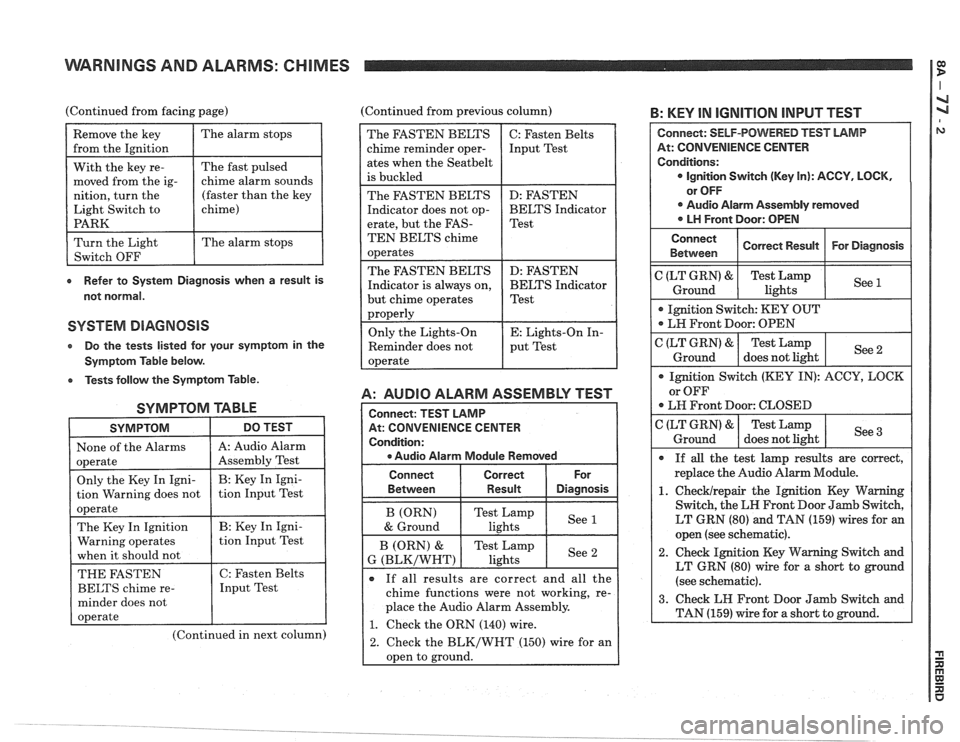
(Continued from facing page) (Continued from previous column) B: KEY IN IGNITION INPUT TEST
e Refer to System Diagnosis when a result is
not normal.
SYSTEM DIAGNOSIS
Do the tests listed lor your symptom in the
Symptom Table below.
e Tests follow the Symptom Table.
SYMPTOM TABLE
SYMPTOM DO TEST I
1 None of the Alarms 1 A: Audio Alarm I
(Continued in next column)
A: AUDIO ALARM ASSEMBLY TEST
At: CONVENIENCE CENTER
e Audio Alarm Module Removed
The FASTEN BELTS
chime reminder oper-
ates when the
Seatbelt
is buckled
The FASTEN BELTS
Indicator does not op-
erate, but the
FAS-
TEN BELTS chime
operates
The FASTEN BELTS
Indicator is always on,
but chime operates
properly
Only the Lights-On
Reminder does not
operate
Connect Correct
Between
I Result Diasnosis
C: Fasten Belts
Input Test
D: FASTEN
BELTS Indicator
Test
D: FASTEN
BELTS Indicator
Test
E: Lights-On In-
put Test
If all results are correct and all the
chime functions were not working, re-
place the Audio Alarm Assembly.
1. Check the ORN (140) wire.
2. Check the BLK/WHT (150) wire for an
oDen to ground.
At: CONVENIENCE CENTER
LT GRN (80) and TAN (159) wires for an
open (see schematic).
2. Check Ignition Key Warning Switch and
LT GRN (80) wire for a short to ground
(see schematic).
Page 1396 of 1825
WARNINGS AND ALARMS: CHIMES
6: FASTEN BELTS INPUT TEST
At: CONVENIENCE CENTER
Ignition Switch: RUN
If the above results are correct, replace
the Audio Alarm Assembly.
Buckle
LH Front
Seatbelt
1. Check PNKIBLK (39) wire for an open.
2. Check the Seatbelt Switch, and BLK (238)
wire for an open (see schematic).
3. Check BLK (238) wire for a short to
ground. If wire is OK, replace the
Seat-
4: FASTEN BELTS INDICATOR TEST
See E (PNKIBLK)
& H (BLK)
Connect: FUSED JUMPER
At: CONVENIENCE CENTER
Condition:
a Audio Alarm Assembly Removed
Connect Correct For
Between Result Diagnosis
Test Lamp
off If
the indicator response was correct, re-
place the Audio Alarm Module.
1. Checklrepair the bulb, the YEL (237)
wire, the BLK (150) wires, and the In-
strument Cluster printed circuit for
opens.
2. Check the Instrument Cluster Printed
Circuit for
a short to Battery.
E: LIGHTS-ON INPUT TEST
At: CONVENIENCE CENTER
0 Audio Alarm Module Removed
Page 1397 of 1825
WARNINGS AND ALARMS: CHIMES
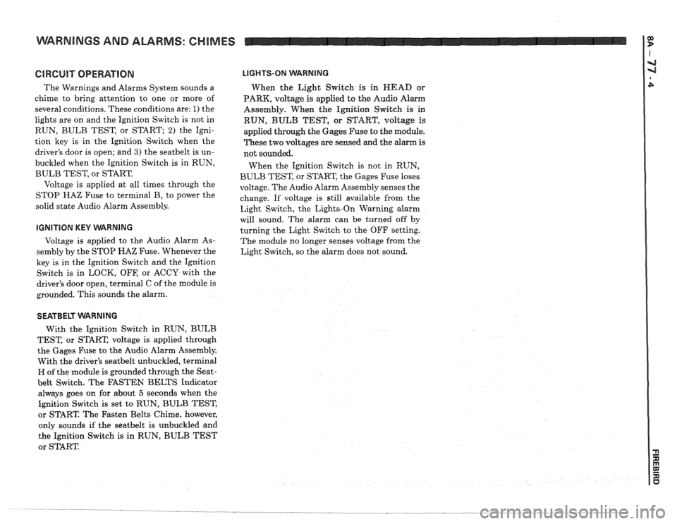
GlRGUlT OPERATION
The Warnings and Alarms System sounds a
chime to bring attention to one or more of
several conditions. These conditions are:
1) the
lights are on and the Ignition Switch is not in
RUN, BULB TEST, or START;
2) the Igni-
tion key is in the Ignition Switch when the
driver's door is open; and
3) the seatbelt is un-
buckled when the Ignition Switch is in RUN,
BULB TEST, or START.
Voltage is applied at all times through the
STOP
HAZ Fuse to terminal B, to power the
solid state Audio Alarm Assembly.
IGNITION KEY VVARNING
Voltage is applied to the Audio Alarm As-
sembly by the STOP HAZ Fuse. Whenever the
key is in the Ignition Switch and the Ignition
Switch is in LOCK, OFF, or ACCY with the
driver's door open, terminal C of the module is
grounded. This sounds the alarm.
LIGHTS-ON WARNING
When the Light Switch is in HEAD or
PARK, voltage
is applied to the Audio Alarm
Assembly. When the Ignition Switch
is in
RUN, BULB TEST, or START, voltage is
applied through the Gages Fuse to the module.
These two voltages are sensed and the alarm is
not sounded.
When the Ignition Switch is not in RUN,
BULB TEST, or START, the Gages Fuse loses
voltage. The Audio Alarm Assembly senses the
change. If voltage is still available from the
Light Switch, the Lights-On Warning alarm
will sound. The alarm can be turned off by
turning the Light Switch to the OFF setting.
The module no longer senses voltage from the
Light Switch, so the alarm does not sound.
SEATBELT WARNING
With the Ignition Switch in RUN, BULB
TEST, or START, voltage is applied through
the Gages Fuse to the Audio Alarm Assembly.
With the driver's
seatbelt unbuckled, terminal
H of the module is grounded through the Seat-
belt Switch. The FASTEN BELTS Indicator
always goes on for about
5 seconds when the
Ignition Switch is set to RUN, BULB TEST,
or START. The Fasten Belts Chime, however,
only sounds if the
seatbelt is unbuckled and
the Ignition Switch
is in RUN, BULB TEST
or START
Page 1400 of 1825
-0 INSTRUMENT PANEL: GAGES CLUSTER
INDICATORS, ILLUMINATION
INTERIOR LIGHTS DIMMING
(V8 VIN F) MULTI-PORT
FUEL INJECTION (V6 VIN S) THROTTLE BODY
INJECTION (V8 VIN E)
- -
CIRCUIT
Page 1405 of 1825
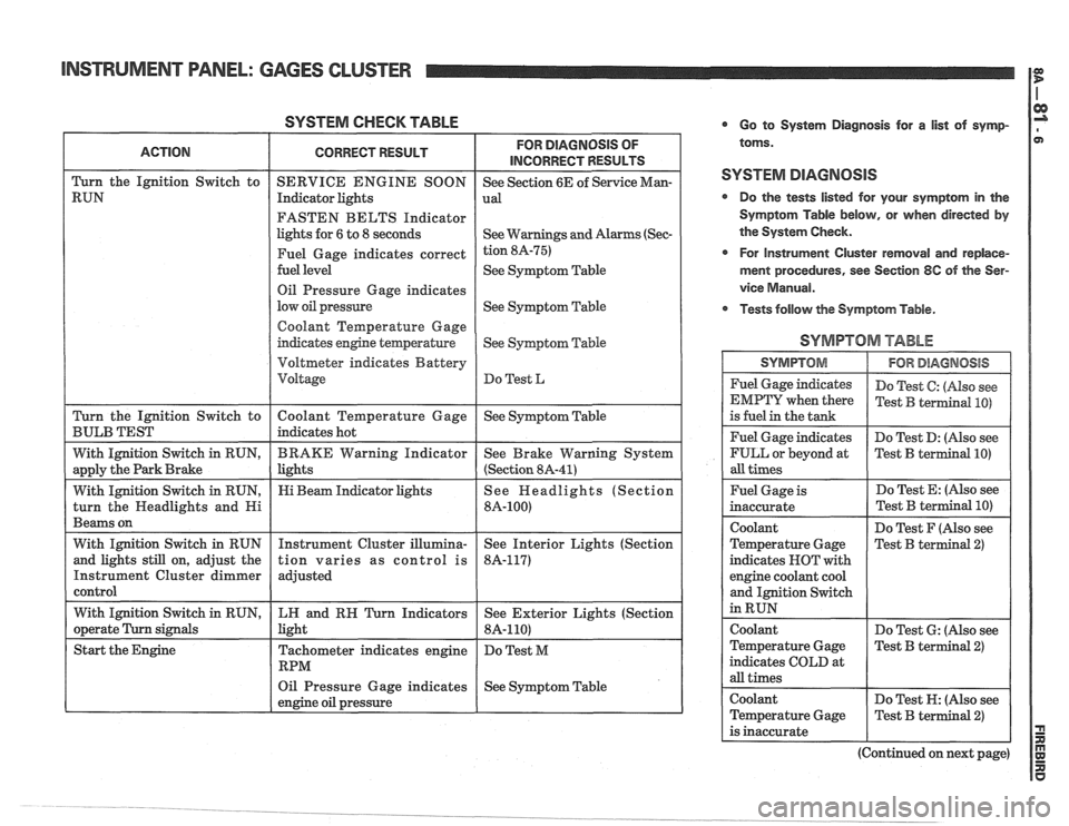
SYSTEM CHECK TABLE
FASTEN BELTS Indicator
lights for
6 to 8 seconds
See
Symptom Table
Oil Pressure Gage indicates
See
Syqtom Table
Coolant Temperature Gage
Voltmeter indicates Battery
Oil Pressure Gage indicates
See Symptom Table
engine oil pressure
L
Go to System Diagnosis for a list of symp-
toms.
SYSTEM DIAGNOSIS
Do the tests listed for your symptom in the
Symptom Table below, or when directed
by
the System Check.
r For Instrument Cluster removal and replace-
ment procedures, see Section
8C of the Ser-
vice
Manual.
Tests follow the Symptom Table.
SYMPTOM TABLE
I SYMPTOM 1 IFORDlAGMOSlS I
Fuel Gage indicates
EMPTY when there
is fuel in the tank
Fuel Gage indicates
FULL or beyond at
all times Do
Test
C: (Also see
Test
B terrnind PO)
Do Test D: (Nso see
Test
B terIllinal PO)
Fuel Gage is
inaccurate
Coolant
Temperature Gage
indicates NOT with
engine coolant cool
and Ignition Switch
in RUN Do
Test E: (Also see
Do Test F (Also see
Test B terminal
2)
coolant
Temperature Gage
indicates COLD at
all times Do
Test
6: (Also see
Test
B terminal 2)
Coolant Do Test N: (Also see
Temperature Gage
Test
B terminal 2)
is inaccurate
(Continued on next page)
Page 1406 of 1825
INSTRUMENT PANEL: GAGES CLUSTER
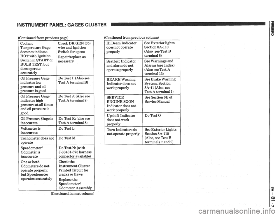
I Oil Pressure Gage
(Continued from previous page)
indicates low
pressure
and oil
pressure is good
Coolant
Temperature Gage
does not indicate
HOT with Ignition
Switch in START or
BULB TEST, but
does operate
accurately
Do Test I: (Also see
Test A
terminal B)
Check DK GRN (35)
wire and Ignition
Switch for opens
Repairlreplace as
necessary
Oil Pressure Gage
indicates high
pressure at
all times
and oil pressure is
good Do
Test
J: (Also see
Test A terminal
8)
Oil Pressure Gage is
inaccurate Do
Test K: (also see
Test A terminal
8)
Do Test L
Tachometer does not
operate
Speedometer1
Odometer is
inaccurate Do
Test M
Do Test N: (with
5-33431-873 harness
connector available)
One or both
Odometers do not
operate properly,
but Speedometer
operates accurately
I
Check the
Instrument Cluster
Printed Circuit for
cracks or flaws
Replace the
Speedometer1
Odometer Assembly
(Continued in next column) (Continued from previous
column)
Hi Beam Indicator
does not operate
properly See
Exterior lights
Section 8A-110
(Also see Test
B
terminal 8)
I operate properly
I
(Also see Test A
I
Seatbelt Indicator
and alarm do not
BRAKE Warning Indicator does not
work properly
I
See Warnings and
Alarms (see Index)
SERVICE
ENGINE SOON
Indicator does not
does not work See
Brake Warning
System, Section
8A-41 (Also, see
Test A terminal
1)
See Section 6E of
1 Service Manual
Do Test O
r
(Also, see Test B
terminals 7 and
9)
Page 1408 of 1825
INSTRUMENT PANEL: GAGES CLUSTER I i
B: CONNECTOR 62 PINOUT TEST
0 IGNITION SWITCH IN RUN EXCEPT
FOR RESISTANCE
MEASUREMENTS
0 MEASURETO GROUND UNLESS
ANOTHER TERMINAL IS GIVEN
0 CLUSTER CONNECTOR 62 AS
SEEN FROM THE DRIVER'S SEAT
WlTH THE INSTRUMENT CLUSTER
REMOVED
IF THE CORRECT VOLTAGE OR
RESISTANCE IS FOUND AT THE
TERMINAL, AND THE CLUSTER
FUNCTION THAT USES THOSE
TERMINALS DOES NOT OPERATE.
CHECK WIRES, BULBS, AND
PRINTED CIRCUIT. IF OK. REPLACE
EITHER THE GAGE OR THE INSTRUMENT CLUSTER (SEE
SECTION 86)
IF THE CORRECT VOLTAGE OR
RESISTANCE IS NOT FOUND AT A TERMINAL, DO THE TEST GIVEN
OR GO TO THE PAGE REFERRED VEHICLE
SPEED SIGNAL
NOT USED INSTRUMENT
CLUSTER ILLUMINATION. VARIABLE
VOLTAGE
WlTH HEAD OR PARK LIGHTS ON AND 11 DIMMER CONTROL ADJUSTED. SEE SECTION I
Page 1412 of 1825
INSTRUMENT PANEL: GAGES CLUSTER
Speedorneter and Odometers
The Speedometer is operated by an electronic
circuit. The Vehicle Speed Sensor (VSS),
located in the transmission, generates an AC
voltage whose frequency is proportional to the
speed of the vehicle. This goes to the Vehicle
Speed Sensor Buffer and then to the Speedom-
eter circuit board in the Instrument Cluster.
The Solid State circuit drives the pointer of the
Speedometer. There is no speedometer cable
in
the vehicle.
The same speed signal from the Vehicle Speed
Buffer is processed by the Speedometer circuit
board to drive the Odometers. They are oper-
ated by a motor that responds to pulses from
the Speedometer circuit.
UpshiN Indicator
With Manual Transmission, the indicator
lights when the car should be shifted to the next
higher gear for better fuel economy. Battery
voltage is applied to one side of the bulb. The
other side of the bulb is switched to ground by
the ECM which uses engine data to compute an
efficient shift point.