Page 1437 of 1825

DRIVER INFORMATION CENTER (DIC) I $
(Continued from previous page)
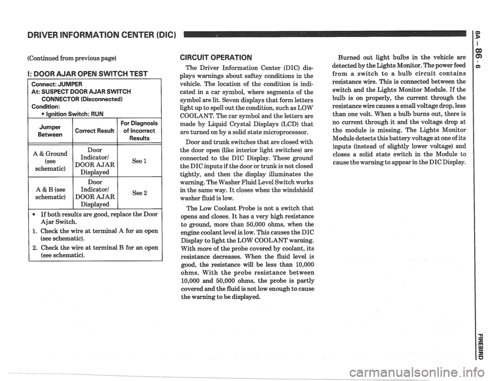
I: DOOR AJAR OPEN SWITCH TEST
At: SUSPECT DOOR AJAR SWITCH
CONNECTOR (Disconnected)
(see schematic).
2. Check the wire at terminal B for an open
(see schematic).
CIRCUIT OPERATION
The Driver Information Center (DIC) dis-
plays warnings about
saftey conditions in the
vehicle. The location of the condition is indi-
cated in a car symbol, where segments of the
symbol are
lit. Seven displays that form letters
light up to spell out the condition, such as LOW
COOLANT. The car symbol and the letters are
made by Liquid
Crystal Displays (LCD) that
are turned on by a solid state microprocessor.
Door and trunk switches that are closed with
the door open (like interior light switches) are
connected to the DIC Display. These ground
the DIC inputs if the door or trunk is not closed
tightly, and then the display illuminates the
warning. The Washer Fluid Level Switch works
in the same way.
It closes when the windshield
washer fluid is low.
The Low Coolant Probe is not a switch that
opens and closes.
It has a very high resistance
to ground, more than 50,000 ohms, when the
engine coolant level is low. This causes the DIC
Display to light the LOW COOLANT w
With more of the probe covered by coolant, its
resistance decreases. When the fluid level is
good, the resistance
will be less than 10,000
ohms. With the probe resistance between
10,000 and 50,000 ohms, the probe is partly
covered and the fluid is not low enough to cause
the warning to be displayed. Burned
out light bulbs in the vehicle are
detected by the Lights Monitor. The power feed
from a switch to a bulb circuit contains
resistance wire. This is connected between the
switch and the Lights Monitor Module.
If the
bulb is on properly, the current through the
resistance wire causes a small voltage drop, less
than one volt. When a bulb burns out, there is
no current through it
and the voltage drop at
the module is missing. The Lights Monitor
Module detects this battery voltage at one of its
inputs (instead of slightly lower voltage) and
closes a solid state switch in the Module to
g to appear in the DIC Display.
Page 1449 of 1825
Page 1450 of 1825

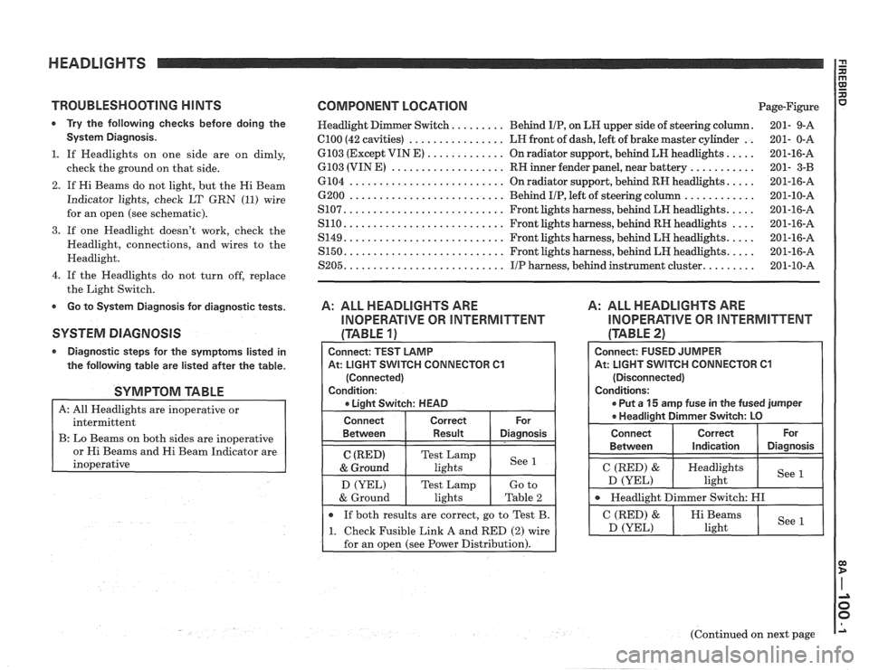
TROUBLESHOOTING HINTS COMPONENT LOCATION Page-Figure
* Try the following checks before doing the Headlight Dimmer Switch. ........ Behind IIP, on LH upper side of steering column. 201- 9-A
System Diagnosis. el00 (42 cavities) ................ LH front of dash, left of brake master cylinder .. 201- 0-A
.... ............. 1. If Headlights on one side are on dimly, 6103 (Except VIN E)
On radiator support, behind LH headlights. 201-16-A
........... ................... check the ground on that side. 6103 (VIN E) RN inner fender panel, near battery 201- 3-B
2. If Hi Beams do not light, but the Hi Beam
Indicator lights, check LT
GRN (11) wire
for an open (see schematic).
3. If one Headlight doesn't work, check the
Headlight, connections, and wires to the
Headlight.
4. If the Headlights do not turn off, replace
the Light Switch.
Go to System Diagnosis for diagnostic tests.
SYSTEM DIAGNOSIS
Diagnostic steps for the symptoms listed in
the following table are listed after the table.
SYMPTOM TABLE
A: All Headlights are inoperative or
intermittent
B: Lo Beams on both sides are inoperative
s and Hi Beam Indicator are
.... .......................... 6104 On radiator support, behind RH headlights. 201-16-A
............ 6200 .......................... Behind IIP, left of steering column 201-10-A
.... .......................... S107. Front lights harness, behind LH headlights. 201-16-A
.... .......................... S110. Front lights harness, behind RH headlights 201-16-A
.... .......................... S149. Front lights harness, behind LH headlights. 201-16-A
.... S150. .......................... Front lights harness, behind LH headlights. 201-16-A
........ S205. .......................... IIP harness, behind instrument cluster. 201-10-A
A: ALL HEADLIGHTS ARE
INOPERATIVE OR INTERMITTENT
(TABLE 1)
A: ALL HEADLIGHTS ARE
INOPERATIVE OR INTERMITTENT
(TABLE 21
Connect: TEST LAMP
At: LIGHT
SVVITCH CONNECTOR C1
(Connected)
Condition:
r Liaht Switch: HEAD
Connect Correct
Between Result Diagnosis
C (RED) Test Lamp
& Ground lights See 1
D
(YEL) Test Lamp
If both results are correct, go to Test B.
1 1. Check Fusible Link A and RED (2) wire
for an open (see Power Distribution).
Connect: FUSED JUMPER
At: LIGHT
SWITCH CONNECTOR C1
(Disconnected)
Conditions:
r Put a 15 amp fuse in the fused jumper
* Headliaiht Dimmer Switch: LO
I Connect 1 Correct ( or 1
Between I Indication 1 Diagnosis I I
I C (RED) & ( Heydlights I See D (YEL) ight
I Headlight Dimmer Switch: HI I
(Continued on next page
Page 1451 of 1825

HEADLIGHTS
(Continued from previous page)
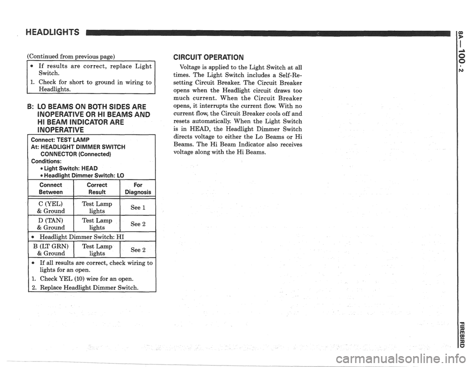
If results are correct, replace Light
Switch.
short to ground in wiring to
B: LO BEAMS ON BOTH SIDES ARE
INOPERATIVE OR HI BEAMS AND
Ell BEAM INDICATOR ARE
Connect: TEST LAMP
At: HEADLIGHT DIMMER SWITCH
CONNECTOR (Connected)
Conditions:
0 Light Switch: HEAD
0 Headlight Dimmer Switch: LO
Connect Correct For
0 If all results are correct, check wiring to
lights for an open.
1. Check YEL (10) wire for an open.
2. Replace Headlight Dimmer Switch.
CIRCUIT OPERATION
Voltage is applied to the Light Switch at all
times. The Light Switch includes a Self-Re-
setting Circuit Breaker. The Circuit Breaker
opens when the Headlight circuit draws too
much current. When the Circuit Breaker
opens, it interrupts the current flow. With no
current flow, the Circuit Breaker cools off and
resets automatically. When the Light Switch
is in
HEAD, the Headlight Dimmer Switch
directs voltage to either the Lo Beams or
Hi
Beams. The Hi Beam Indicator also receives
voltage along with the
Hi Beams.
Page 1452 of 1825
HEADLIGHTS: FOG LlGHTS
DISTRIBUTION
FUSE
- BLOCK -
TO INSTRUMENT CLUSTER
TO C103 ON AND ClOO PIN A2 ON NEXT PAGE
NEXT PAGE TO
FOG LIGHT SWITCH
ON NEXT PAGE
Page 1454 of 1825

HEADLIGHTS: FOG LIGHTS
TROUBLESHOOTING HINTS
r Try the following checks before doing the
System Diagnosis
.
1 . Check that the Headlights and Park Lights
work properly before troubleshooting the
Fog Lights
.
2 . If one Fog Light doesn't work, check the
Fog Light. connections. and wires to the
Fog Light
.
Go to System Diagnosis for diagnostic tests .
SYSTEM DIAGNOSIS
Do the following test if the
operate
.
-., U .
Fog Lights do not
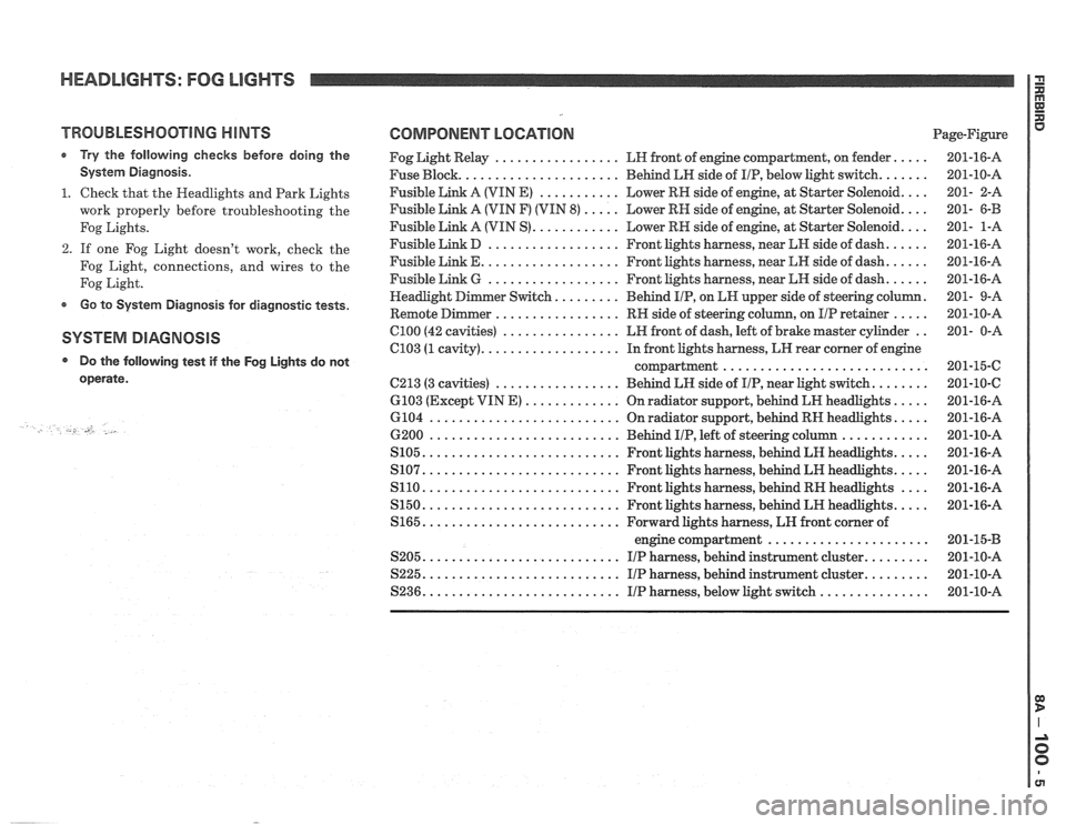
COMPONENT LOCATION Page-Figure
Fog Light Relay
................. LH front of engine compartment. on fender .....
Fuse Block ...................... Behind LH side of IIP. below light switch .......
Fusible Link A (VIN E) ........... Lower RN side of engine. at Starter Solenoid ....
Fusible Link A (VIN F) (VIN 8) ..... Lower RH side of engine. at Starter Solenoid ....
Fusible Link A (VIN S) ............ Lower RH side of engine. at Starter Solenoid ....
Fusible Link D .................. Front lights harness. near kH side of dash ......
Fusible Link E ................... Front lights harness. near LH side of dash ......
Fusible Link 6 .................. Front lights harness. near LN side of dash ......
......... . er Switch Behind IIP. on EN upper side
of steering column
Remote
Dimmer ................. RH side of steering column. on IIP retainer ..... .
C100 (42 cavities) ................ LH front of dash. left of brake master cylinder ..
C103 (1 cavity) ................... In front lights harness. LH rear corner of engine
compartment
............................
C213 (3 cavities) ................. Behind LH side of IIP. near Light switch ........
6103 (Except VIN E) ............. On radiator support. behind LR headlights .....
6104 .......................... On radiator support. behind RN headlights .....
6200 .......................... Behind IIP. left of steering column ............
S105 ........................... Front lights harness. behind LH headlights .....
S107 ........................... Front lights harness. behind LH headlights .....
S110 ........................... Front lights harness. behind RH headlights ....
S150 ........................... Front lights harness. behind LH headlights .....
S165 ........................... Forward lights harness. LH front corner of
engine compartment
......................
S205 ........................... I/P harness. behind instrument cluster .........
S225 ........................... I/P harness. behind instrument cluster .........
S236 ........................... IIP harness. below light switch ...............
Page 1455 of 1825
HEADLIGHTS: FOG LIGHTS
FOG LIGHTS DO NOT OPERATE CIRCUIT OPERATlON
The Fog Lights are controlled by the Light
Switch. They can be turned on with the Park
or Headlights on. With the Hi Beams on, the
Fog Lights go out.
The Fog Light Relay controls battery volt-
age to the Fog Lights. The Fog Light Switch
applies voltage to the relay coil. The relay coil
is grounded through the Hi Beam filaments.
When the Hi Beams come on, battery voltage
is at both sides of the relay coil. The relay and
the Fog Lights turn off.
At: FOG LIGHT RELAY CONNECTOR
(Disconnected)
1. Check the Fog Light Switch and BRN (9)
and BRNIWNT (909) wires for an open
(see schematic).
2. Check LT GRN (11) wire for an open.
3. Check Fusible Link G and RED/WNT (2)
Page 1457 of 1825
a HEADLIGHT DOORS l e
----- FUSIBLE
HEADLIGHTS: FOG LIGHTS