1987 SUZUKI GRAND VITARA coolant
[x] Cancel search: coolantPage 22 of 962
5) Remove timing belt outside cover. Inspect
the belt for damage or wear. When any
damage or wear is found on the belt, replace
it.
If belt replacement is necessary, be sure to
install the belt properly.
6) Remove cylinder head cover and loosen all
valve adjusting screws all the way to permit
free rotation of camshaft.
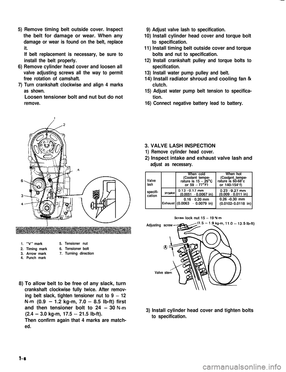
7) Turn crankshaft clockwise and align 4 marks
as shown.
Loosen tensioner bolt and nut but do not
remove.
9) Adjust valve lash to specification.
10) Install cylinder head cover and torque bolt
to specification.
11) Install timing belt outside cover and torque
bolts and nut to specification.
12) Install crankshaft pulley and torque bolts to
specification.
13) Install water pump pulley and belt.
14) Install radiator shroud and cooling fan &
clutch.
15) Adjust water pump belt tension to specifica-
tion.
16) Connect negative battery lead to battery.
3. VALVE LASH INSPECTION
1) Remove cylinder head cover.
2) Inspect intake and exhaust valve lash and
adjust as necessary.
1.“V” mark5.Tensioner nut
2.Timing mark6.Tensioner bolt
3.Arrow mark7.Turning direction4.Punch mark
8) To allow belt to be free of any slack, turn
crankshaft clockwise fully twice. After remov-
ing belt slack, tighten tensioner nut to 9 - 12
N-m (0.9- 1.2 kg-m, 7.0 - 8.5 lb-ft) first
and then tensioner bolt to 24 - 30 N-m
(2.4 - 3.0 kg-m, 17.5 - 21.5 lb-ft).
Then confirm again that 4 marks are match-
ed.
Valvelash specifi-cation
When coldWhen hot(Coolant tempe-(Coolant tempe---rature is 15 - 25’Crature is 60-68 c or 59 - or 140-154 f)
0.13-0.17mm 0.23-0.27mmIntake(0.0051- 0.0067 in)(0.009 - 0.011 in)
0.16-0.20 mm0.26 -0.30 mm(0.0102- Exhaust (0.0063 - 0.0079 in) 0.0118 in)
Screw lock nut 15 - 19 N.m
Adjusting screw
Valve ste
.5 lb-ft)
3) Install cylinder head cover and tighten bolts
to specification.
l-6
Page 23 of 962
NOTE:
Steps 1) - 6) outlined above must be performed
with ENGINE NOT RUNNING. For step 7),
be sure to have adequate ventilation while
engine is running
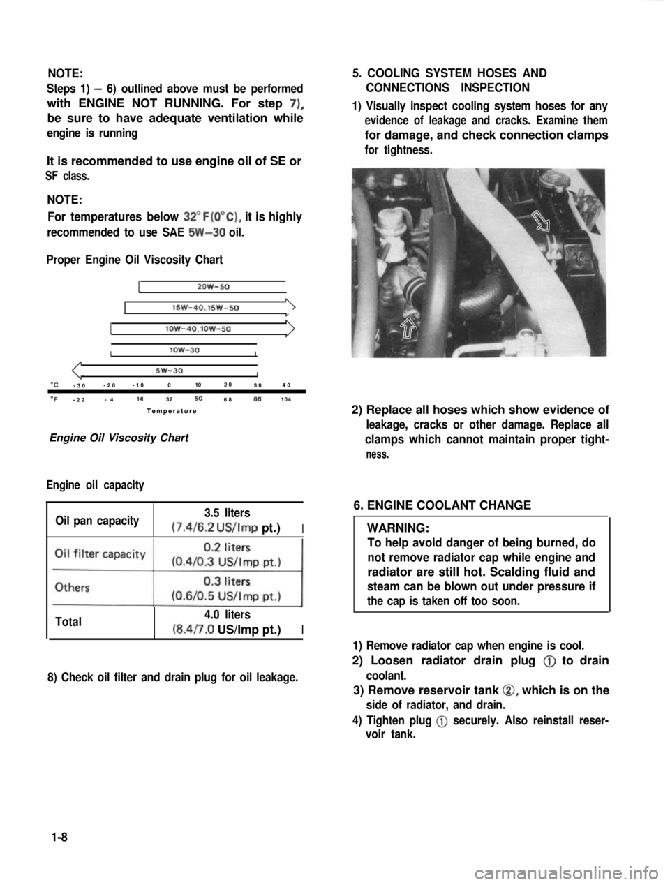
It is recommended to use engine oil of SE or
SF class.
NOTE:For temperatures below
32”F(O”C), it is highly
recommended to use SAE 5W-30 oil.
Proper Engine Oil Viscosity Chart
12OW-50
lSW-40.15w-501
Ilow-4O.lOW-50
Ilow-30I
5w-30I“C-3 0 -2
0 -1
0 0 102
0
30 4
0
OF-2 2 -
4 14
32506886104
Temperatur e
Engine Oil Viscosity Chart
Engine oil capacity
Oil pan capacity 3.5 liters (7.4/6.2
US/Imp pt.)I
Total 4.0 liters(8.4/7.0 US/Imp pt.)I
8) Check oil filter and drain plug for oil leakage.
5. COOLING SYSTEM HOSES AND
CONNECTIONS INSPECTION
1) Visually inspect cooling system hoses for any
evidence of leakage and cracks. Examine them
for damage, and check connection clamps
for tightness.
2) Replace all hoses which show evidence of
leakage, cracks or other damage. Replace all
clamps which cannot maintain proper tight-
ness.
6. ENGINE COOLANT CHANGE
WARNING:
To help avoid danger of being burned, do
not remove radiator cap while engine and
radiator are still hot. Scalding fluid and
steam can be blown out under pressure if
the cap is taken off too soon.
1) Remove radiator cap when engine is cool.
2) Loosen radiator drain plug @
to drain
coolant.
3) Remove reservoir tank 0, which is on the
side of radiator, and drain.
4) Tighten plug
@ securely. Also reinstall reser-
voir tank.
1-8
Page 25 of 962
CAUTION:
When changing engine coolant, use mixture
of 56% water and 50% GOLDEN CRUISER
1200for the market where ambient tem-
perature falls lower than -16°C (3°F) in
winter and mixture of 70% water and
30% GOLDEN CRUISER 1200for the
market where ambient temperature doesn’t
fall lower than -16°C (3” F).
Even in a market where no freezing tempe-
rature is anticipated, mixture of 70% water
and 30% GOLDEN CRUISER 1200
should be used for the purpose of corro-
sion protection and lubrication.
7. EXHAUST PIPES AND MOUNTINGS
INSPECTION
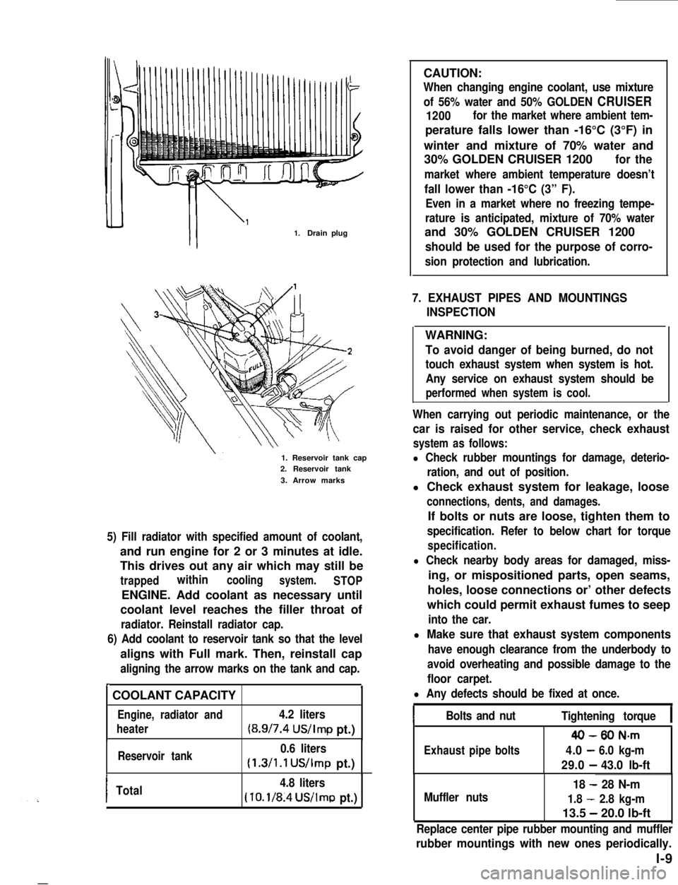
1.Drain plug
1. Reservoir tank cap2. Reservoir tank
3. Arrow marks
5) Fill radiator with specified amount of coolant,
and run engine for 2 or 3 minutes at idle.
This drives out any air which may still be
trappedwithincoolingsystem.STOP
ENGINE. Add coolant as necessary until
coolant level reaches the filler throat of
radiator. Reinstall radiator cap.
6) Add coolant to reservoir tank so that the level
aligns with Full mark. Then, reinstall cap
aligning the arrow marks on the tank and cap.
r.
COOLANT CAPACITY
Engine, radiator and4.2 liters
heater(8.9/7.4 US/Imp pt.)
Reservoir tank0.6 liters
(1.3/1.1 US/Imp pt.)
ITotal4.8 liters
(10.1/8.4US/lmp pt.)
WARNING:
To avoid danger of being burned, do not
touch exhaust system when system is hot.
Any service on exhaust system should be
performed when system is cool.
When carrying out periodic maintenance, or the
car is raised for other service, check exhaust
system as follows:
l Check rubber mountings for damage, deterio-
ration, and out of position.
l Check exhaust system for leakage, loose
connections, dents, and damages.
If bolts or nuts are loose, tighten them to
specification. Refer to below chart for torque
specification.
l Check nearby body areas for damaged, miss-
ing, or mispositioned parts, open seams,
holes, loose connections or’ other defects
which could permit exhaust fumes to seep
into the car.
l Make sure that exhaust system components
have enough clearance from the underbody to
avoid overheating and possible damage to the
floor carpet.
l Any defects should be fixed at once.
IBolts and nutTightening torqueI
40-80 N-m
Exhaustpipebolts4.0-6.0 kg-m
29.0-43.0 lb-ft
Muffler nuts
18 - 28 N-m
1.8 - 2.8 kg-m
13.5 - 20.0 lb-ft
Replace center pipe rubber mounting and muffler
rubber mountings with new ones periodically.
l-9
Page 27 of 962
1. CHARCOAL CANISTER REPLACEMENT
WARNING:
The following cautions should be always
observed.
l Disconnect negative cable at battery.
l DO NOT smoke and place “NO SMOK-
ING” signs near work area.
l Be sure to have COZ fire extinguisher
handy.
l Wear safety glasses.
l To release the fuel vapor pressure in
fuel tank, remove the fuel tank cap and
then reinstall it.
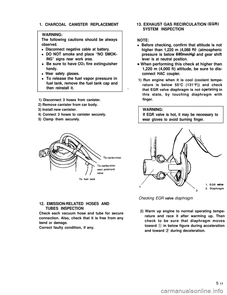
1) Disconnect 3 hoses from canister.
2) Remove canister from car body.
3) Install new canister.
4) Connect 3 hoses to canister securely.
5) Clamp them securely.
//valve
To fuel tank
12. EMISSION-RELATED HOSES AND
TUBES INSPECTION
Check each vacuum hose and tube for secure
connection. Also, check that it is free from any
bend or damage.
Correct faulty condition, if any.
13. EXHAUST GAS RECIRCULATION (EGR)
SYSTEM INSPECTION
NOTE:
l Before checking, confirm that altitude is not
higher than 1,220 m (4,088 ftt) (atmospheric
pressure is below 680mmHg) and gear shift
lever is at neutral position.
o When performing this check at higher than
1,220 m (4,000 ft) altitude, be sure to dis-
connect HAC coupler.
.
1) Run engine when it is cool (coolant tempe-
rature is below 55°C (131°F)) and check
that EGR valve diaphragm is not operating in
this state, by touching diaphragm with
finger.
WARNING:
If EGR valve is hot, it may be necessary to
wear gloves to avoid burning finger.
1. EGR valve
22. Diaphragm
Checking EGR valve diaphragm
2) Warm up engine to normal operating tempe-
rature and race it after warming up. Then
check to be sure that diaphragm moves
toward @ in below figure during acceleration
and toward @ during deceleration.
l- 11
Page 45 of 962
9
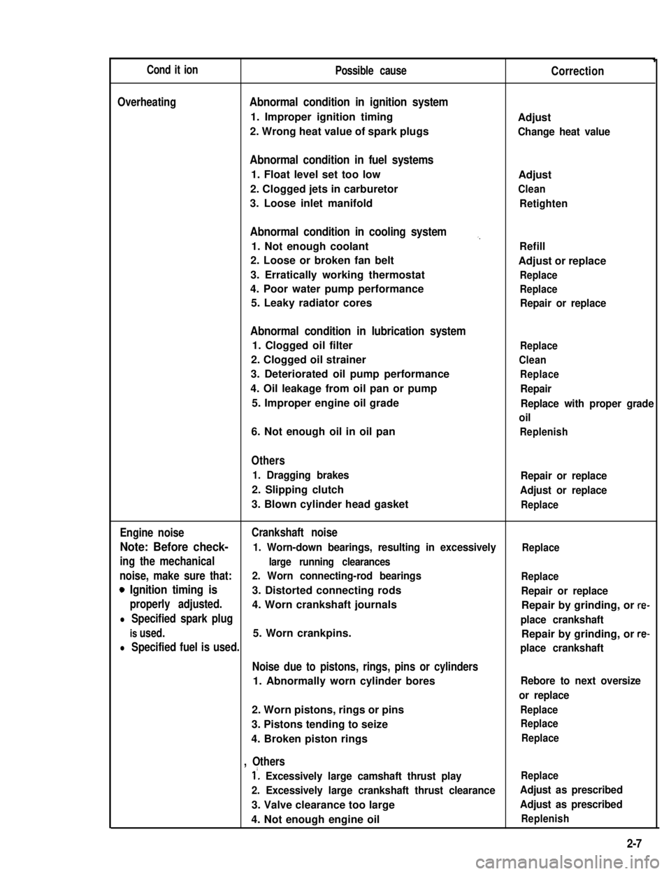
Cond it ionPossible causeCorrection
OverheatingAbnormal condition in ignition system
1. Improper ignition timingAdjust
2. Wrong heat value of spark plugsChange heat value
Abnormal condition in fuel systems
1. Float level set too lowAdjust
2. Clogged jets in carburetorClean
3. Loose inlet manifoldRetighten
Abnormal condition in cooling system,,
1. Not enough coolantRefill
2. Loose or broken fan beltAdjust or replace
3. Erratically working thermostatReplace
4. Poor water pump performanceReplace
5. Leaky radiator coresRepair or replace
Abnormal condition in lubrication system
1. Clogged oil filterReplace
2. Clogged oil strainerClean
3. Deteriorated oil pump performanceReplace
4. Oil leakage from oil pan or pumpRepair
5. Improper engine oil gradeReplace with proper grade
oil
6. Not enough oil in oil panReplenish
Others
1. Dragging brakesRepair or replace
2. Slipping clutchAdjust or replace
3. Blown cylinder head gasketReplace
Engine noiseCrankshaft noise
Note: Before check- 1. Worn-down bearings, resulting in excessivelyReplace
ing the mechanicallarge running clearances
noise, make sure that:2. Worn connecting-rod bearingsReplace
0 Ignition timing is3. Distorted connecting rodsRepair or replace
properly adjusted.4. Worn crankshaft journalsRepair by grinding, or re-
l Specified spark plugplace crankshaft
is used.5. Worn crankpins.Repair by grinding, or re-
l Specified fuel is used.place crankshaft
Noise due to pistons, rings, pins or cylinders
1. Abnormally worn cylinder boresRebore to next oversize
or replace
2. Worn pistons, rings or pinsReplace
3. Pistons tending to seizeReplace
4. Broken piston ringsReplace
, Others
1’. Excessively large camshaft thrust playReplace
2. Excessively large crankshaft thrust clearanceAdjust as prescribed
3. Valve clearance too largeAdjust as prescribed
4. Not enough engine oilReplenish
2-7
Page 110 of 962
3-7. ENGINE INSTALLATION
1) Lower engine with transmission into vehicle,
but do not remove lifting device.
2) Tighten engine mounting bracket bolts
(right and left) and transmission mounting
bolts to specification. Refer to p. 3-58.
3) Remove lifting device.
4) Reverse removal procedures for installation
of remainder.
5) Adjust accelerator cable play and clutch
cable play.
6) Connect vacuum hoses securely. Refer to
section 5 “EMISSION CONTROL SYSTEM”
for correct connection.
7) Connect wire harnesses and couplers secure-
IY.
8) Tighten bolts and nuts to specified torque.
For individual specification, refer to each
section.
9) Fill specified amount of specified trans-
mission oil and engine oil. For the detail,
refer to SECTION 1 PERIODIC MAINTE-
NANCE SERVICE of this manual.
10) After adjusting water pump belt tension to
specification, fill specified amount of engine
cooling water.
11) Before starting engine, check again to ensure
that all parts once disassembled or discon-
nected are back in place securely.
12)Start engine and check ignition timing. If
it is not to specified timing, adjust it, referr-
ing to SECTION 8 of this manual.
13) After engine is started, check for oil leak,
abnormal noise and other malcondition.
Also, check each part for operation.
3-8. ENGINE MAINTENANCE SERVICE
Fan Belt
Adjust belt tension as outlined in SECTION 6
ENGINE COOLING SYSTEM (p. 6-10).
Ignition Timing
Refer to IGNITION TIMING, Page 8-9.
Carburetor
fidjustments to be made are detailed in SEC-
TION 4 (p. 4-19).
Valve Lash (Clearance)
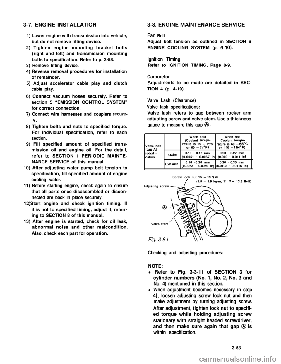
Valve lash specifications:
Valve lash refers to gap between rocker arm
adjusting screw and valve stem. Use a thickness
gauge to measure this gap @.
When coldWhen hot(Coolant tempe-(Coolant tempa-
Valve lashrature is 15 - 25%rature is 60 - 66’C
(gap A)or 69 - 77’F)or 140 - 154’F)
specif i-0.13 - 0.17 mm0.23 - 0.27 mmcationIntake(0.0051 - 0.0067 in) (0.009 - 0.011 in)
Exhaust0.16 -0.20 mm0.26 - 0.30 mm(0.0063 - 0.0079 in) (0.0102 - 0.0116 in)
Screw lock nut 15 - 19 N.m(1.5 - 1.9 kg-m, 11 .O - 13.5 lb-ft)
Adjusting screw
8
Valve stem
Fig. 3-8-l
Checking and adjusting procedures:
NOTE:
l Refer to Fig. 3-3-11 of SECTION 3 for
cylinder numbers (No. 1, No. 2, No. 3 and
No. 4) mentioned in this section.
l When adjustment becomes necessary in step
4), loosen adjusting screw lock nut and then
make adjustment by turning adjusting screw.
After adjustment, tighten lock nut to specifi-
ed torque while holding adjusting screw
stationary with straight headed screwdriver,
and then make sure again that gap @ is
within specification.
3-53
Page 112 of 962
Engine Coolant
This subject is covered in SECTION 6 ENGINE
COOLING SYSTEM.
Exhaust Line and Muffler
Inspect each exhaust line connection for tight-
ness, and examine muffler and other parts for
evidence of breakage and leakage of gases.
Repair or replace defective parts, if any.
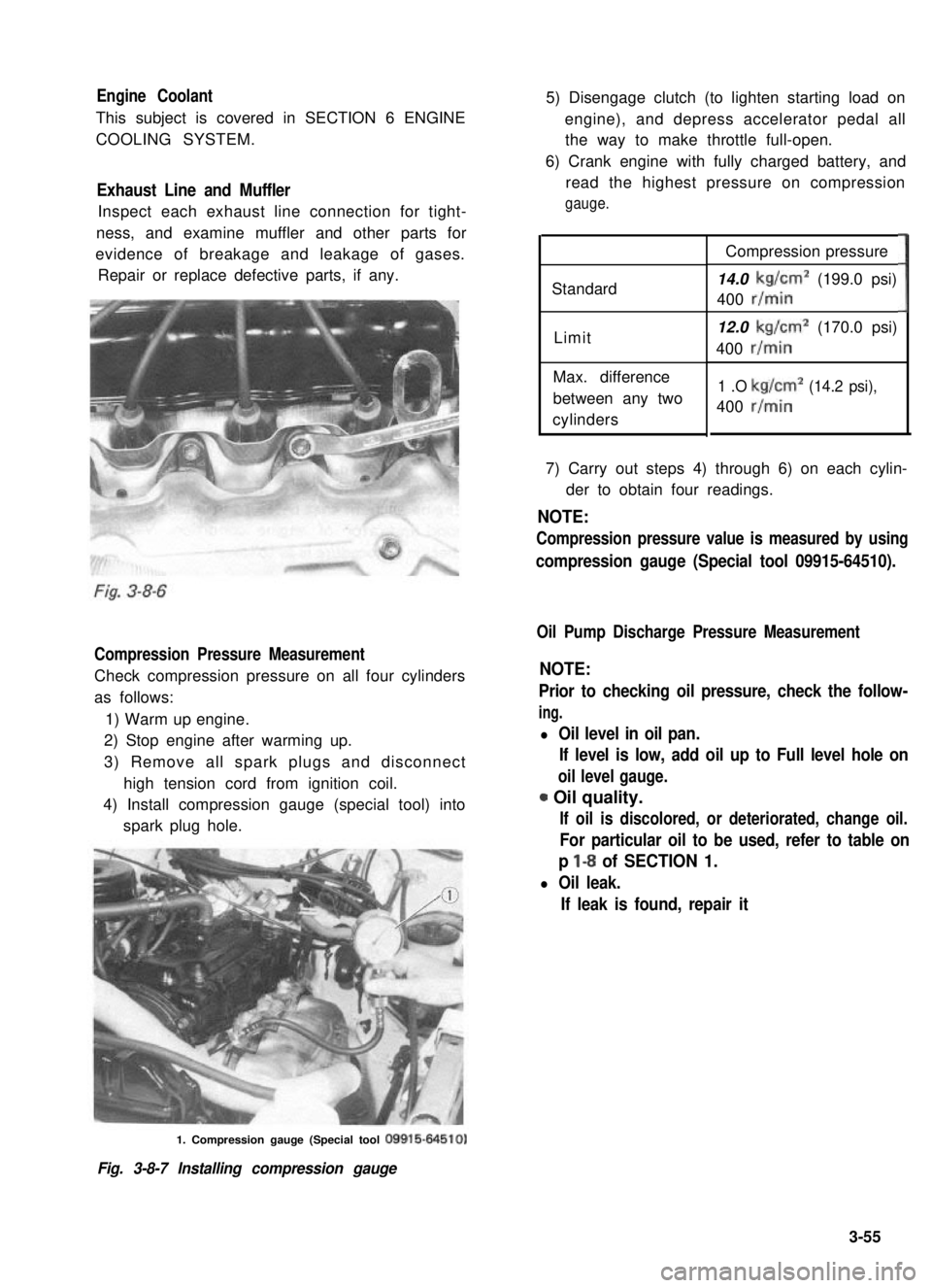
Compression Pressure Measurement
Check compression pressure on all four cylinders
as follows:
1) Warm up engine.
2) Stop engine after warming up.
3) Remove all spark plugs and disconnect
high tension cord from ignition coil.
4) Install compression gauge (special tool) into
spark plug hole.
5) Disengage clutch (to lighten starting load on
engine), and depress accelerator pedal all
the way to make throttle full-open.
6) Crank engine with fully charged battery, and
read the highest pressure on compression
gauge.
Standard
Limit
Max. difference
between any two
cylinders
Compression pressure
14.0 kg/cm2 (199.0 psi)
400 r/min
12.0 kg/cm2 (170.0 psi)
400 r/min
1 .O kg/cm2 (14.2 psi),
400 r/min
3
7) Carry out steps 4) through 6) on each cylin-
der to obtain four readings.
NOTE:
Compression pressure value is measured by using
compression gauge (Special tool 09915-64510).
Oil Pump Discharge Pressure Measurement
NOTE:
Prior to checking oil pressure, check the follow-
ing.
l Oil level in oil pan.
If level is low, add oil up to Full level hole on
oil level gauge.
0 Oil quality.
If oil is discolored, or deteriorated, change oil.
For particular oil to be used, refer to table on
p l-8 of SECTION 1.
l Oil leak.
If leak is found, repair it
1. Compression gauge (Special tool 09915-64510)
Fig. 3-8-7 Installing compression gauge
3-55
Page 125 of 962
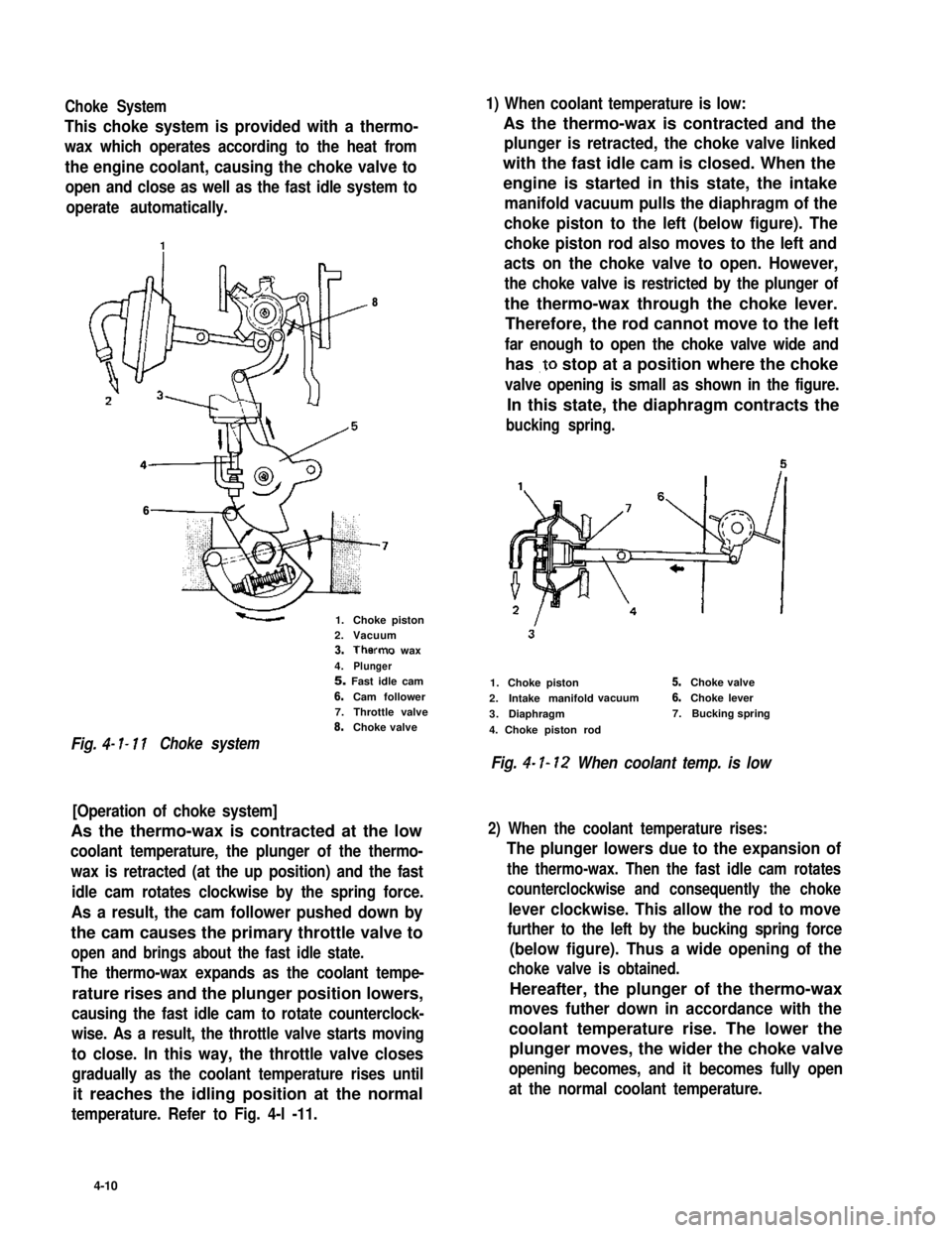
Choke System1) When coolant temperature is low:
This choke system is provided with a thermo-
wax which operates according to the heat from
the engine coolant, causing the choke valve to
open and close as well as the fast idle system to
operate automatically.
As the thermo-wax is contracted and the
plunger is retracted, the choke valve linked
with the fast idle cam is closed. When the
engine is started in this state, the intake
manifold vacuum pulls the diaphragm of the
choke piston to the left (below figure). The
choke piston rod also moves to the left and
acts on the choke valve to open. However,
the choke valve is restricted by the plunger of
the thermo-wax through the choke lever.
Therefore, the rod cannot move to the left
far enough to open the choke valve wide and
has .to stop at a position where the choke
valve opening is small as shown in the figure.
In this state, the diaphragm contracts the
bucking spring.
8
6
1.Choke piston2.Vacuum3.Therms wax
4.Plunger5. Fast idle cam
6.Cam follower7.Throttle valve8.Choke valve
Fig. 4- I- 11Choke system
[Operation of choke system]
As the thermo-wax is contracted at the low
coolant temperature, the plunger of the thermo-
wax is retracted (at the up position) and the fast
idle cam rotates clockwise by the spring force.
As a result, the cam follower pushed down by
the cam causes the primary throttle valve to
open and brings about the fast idle state.
The thermo-wax expands as the coolant tempe-
rature rises and the plunger position lowers,
causing the fast idle cam to rotate counterclock-
wise. As a result, the throttle valve starts moving
to close. In this way, the throttle valve closes
gradually as the coolant temperature rises until
it reaches the idling position at the normal
temperature. Refer to Fig. 4-l -11.
1.Choke piston
2.Intake manifoldvacuum
3.Diaphragm
4. Choke piston rod
5.Choke valve
6.Choke lever
7.Bucking spring
Fig. 4- I- 12 When coolant temp. is low
2) When the coolant temperature rises:
The plunger lowers due to the expansion of
the thermo-wax. Then the fast idle cam rotates
counterclockwise and consequently the choke
lever clockwise. This allow the rod to move
further to the left by the bucking spring force
(below figure). Thus a wide opening of the
choke valve is obtained.
Hereafter, the plunger of the thermo-wax
moves futher down in accordance with the
coolant temperature rise. The lower the
plunger moves, the wider the choke valve
opening becomes, and it becomes fully open
at the normal coolant temperature.
4-10