1987 SUZUKI GRAND VITARA wheel bolts
[x] Cancel search: wheel boltsPage 20 of 962
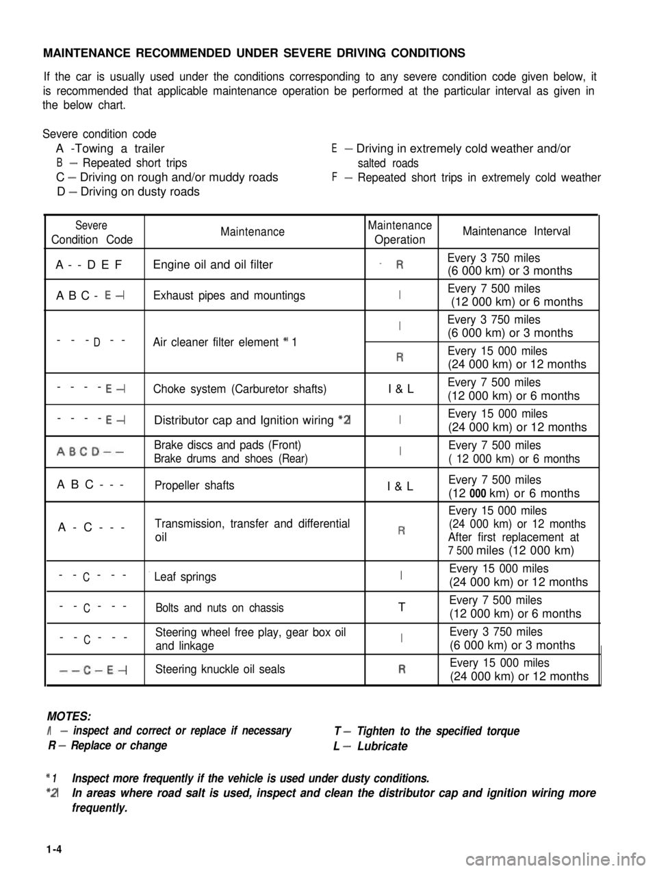
MAINTENANCE RECOMMENDED UNDER SEVERE DRIVING CONDITIONS
If the car is usually used under the conditions corresponding to any severe condition code given below, it
is recommended that applicable maintenance operation be performed at the particular interval as given in
the below chart.
Severe condition code
A -Towing a trailer
B- Repeated short trips
C - Driving on rough and/or muddy roads
D - Driving on dusty roads
E- Driving in extremely cold weather and/or
salted roads
F- Repeated short trips in extremely cold weather
Severe
Condition CodeMaintenanceMaintenance
OperationMaintenance Interval
A--DEFEngine oil and oil filter_ REvery 3 750 miles
(6 000 km) or 3 months
ABC- E-Exhaust pipes and mountingsIEvery 7 500 miles
(12 000 km) or 6 months
IEvery 3 750 miles
D(6 000 km) or 3 months--- --Air cleaner filter element * 1
REvery 15 000 miles
(24 000 km) or 12 months
----E-Choke system (Carburetor shafts)I&LEvery 7 500 miles
(12 000 km) or 6 months
----E-Distributor cap and Ignition wiring “2IEvery 15 000 miles
(24 000 km) or 12 months
ABCD--Brake discs and pads (Front)IEvery 7 500 miles
Brake drums and shoes (Rear)( 12 000 km) or 6 months
ABC---Propeller shaftsI&LEvery 7 500 miles
(12 000 km) or 6 months
Every 15 000 miles
A-C---Transmission, transfer and differential(24 000 km) or 12 months
oilRAfter first replacement at
7 500 miles (12 000 km)
CEvery 15 000 miles-- ---’ Leaf springsI(24 000 km) or 12 months
C-- ---Bolts and nuts on chassisTEvery 7 500 miles
(12 000 km) or 6 months
CSteering wheel free play, gear box oil-- ---and linkageIEvery 3 750 miles
(6 000 km) or 3 months
--C-E-Steering knuckle oil sealsREvery 15 000 miles
(24 000 km) or 12 months
MOTES:
I- inspect and correct or replace if necessary
R - Replace or change
T - Tighten to the specified torque
L - Lubricate
* 1Inspect more frequently if the vehicle is used under dusty conditions.
*2In areas where road salt is used, inspect and clean the distributor cap and ignition wiring more
frequently.
1-4
Page 37 of 962
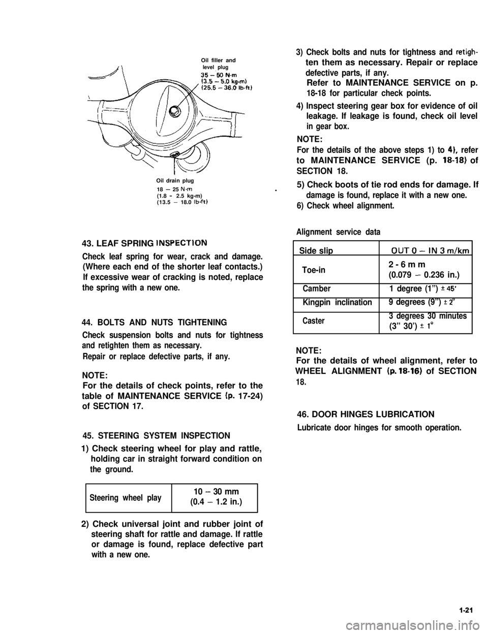
Oil filler andlevel plug
Oil drain plug
18 - 25 N.m(1.8 - 2.5 kg-m)(13.5 - 18.0 lb-ft)
43. LEAF SPRING lNSPECTlON
Check leaf spring for wear, crack and damage.
(Where each end of the shorter leaf contacts.)
If excessive wear of cracking is noted, replace
the spring with a new one.
44. BOLTS AND NUTS TIGHTENING
Check suspension bolts and nuts for tightness
and retighten them as necessary.
Repair or replace defective parts, if any.
NOTE:
For the details of check points, refer to the
table of MAINTENANCE SERVICE (p. 17-24)
of SECTION 17.
45. STEERING SYSTEM INSPECTION
1) Check steering wheel for play and rattle,
holding car in straight forward condition on
the ground.
Steering wheel play10 - 30 mm
(0.4 - 1.2 in.)
3) Check bolts and nuts for tightness and retigh-
ten them as necessary. Repair or replace
defective parts, if any.
Refer to MAINTENANCE SERVICE on p.
18-18 for particular check points.
4) Inspect steering gear box for evidence of oil
leakage. If leakage is found, check oil level
in gear box.
NOTE:
For the details of the above steps 1) to 41, refer
to MAINTENANCE SERVICE (p. 18-18) of
SECTION 18.
.5) Check boots of tie rod ends for damage. If
damage is found, replace it with a new one.
6) Check wheel alignment.
Alignment service data
Side slipOUTO-IN3m/km
Toe-in2-6mm
(0.079 - 0.236 in.)
Camber1 degree (1”) *45’
Kingpin inclination 9 degrees (9”) f 2’
Caster3 degrees 30 minutes
(3” 30’) f I0
NOTE:
For the details of wheel alignment, refer to
WHEEL ALIGNMENT (p. 18-16) of SECTION
18.
46. DOOR HINGES LUBRICATION
Lubricate door hinges for smooth operation.
2) Check universal joint and rubber joint of
steering shaft for rattle and damage. If rattle
or damage is found, replace defective part
with a new one.
1-21
Page 50 of 962
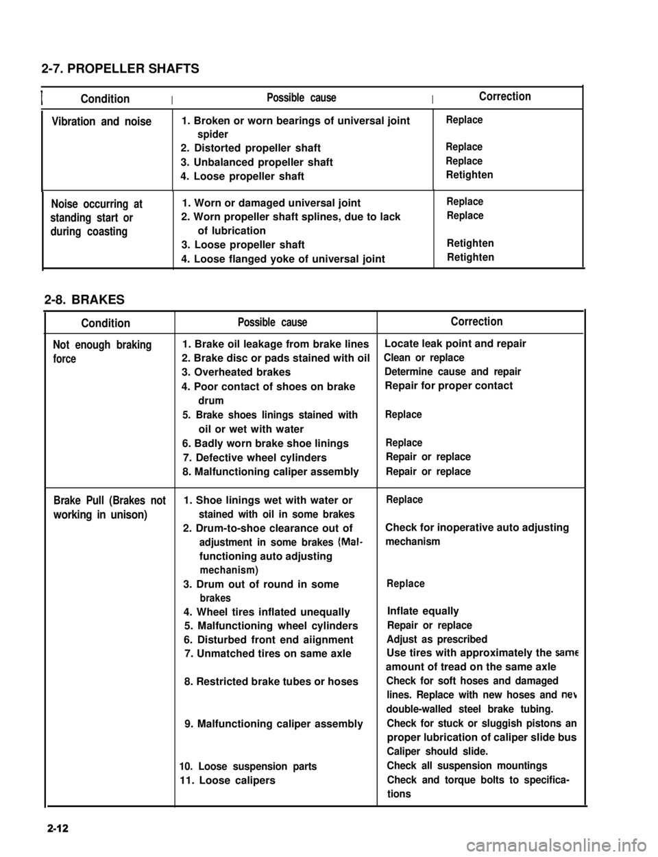
2-7. PROPELLER SHAFTS
IConditionIPossible causeICorrection
Vibration and noise1. Broken or worn bearings of universal joint
spider
2. Distorted propeller shaft
3. Unbalanced propeller shaft
4. Loose propeller shaft
Replace
Replace
Replace
Retighten
Noise occurring at
standing start or
during coasting
1. Worn or damaged universal joint
2. Worn propeller shaft splines, due to lack
of lubrication
3. Loose propeller shaft
4. Loose flanged yoke of universal joint
Replace
Replace
Retighten
Retighten
2-8. BRAKES
Condition
Not enough braking
force
Possible causeCorrection
1. Brake oil leakage from brake linesLocate leak point and repair
2. Brake disc or pads stained with oilClean or replace
3. Overheated brakesDetermine cause and repair
4. Poor contact of shoes on brakeRepair for proper contact
drum
5. Brake shoes linings stained with
oil or wet with water
Replace
6. Badly worn brake shoe liningsReplace
7. Defective wheel cylindersRepair or replace
8. Malfunctioning caliper assemblyRepair or replace
Brake Pull (Brakes not1. Shoe linings wet with water orReplace
working in unison)stained with oil in some brakes
2. Drum-to-shoe clearance out ofCheck for inoperative auto adjusting
adjustment in some brakes (Mal-mechanism
functioning auto adjusting
mechanism)
3. Drum out of round in some
brakes
Replace
4. Wheel tires inflated unequally
5. Malfunctioning wheel cylinders
6. Disturbed front end aiignment
7. Unmatched tires on same axle
8. Restricted brake tubes or hoses
9. Malfunctioning caliper assembly
10. Loose suspension parts
11. Loose calipers
Inflate equally
Repair or replace
Adjust as prescribed
Use tires with approximately the same
amount of tread on the same axle
Check for soft hoses and damaged
lines. Replace with new hoses and net
double-walled steel brake tubing.
Check for stuck or sluggish pistons an
proper lubrication of caliper slide bus
Caliper should slide.
Check all suspension mountings
Check and torque bolts to specifica-
tions
2-12
Page 51 of 962

Condition
Excessive pedal travel
(Pedal stroke too
large)
Possible cause
1. Partial brake system failure
2. Insufficient fluid in master
cylinder reservoirs
Correction
Check diagonal brake systems and
repair as necessary
Fill reservoirs with approved brake
fluid. Check for leaks and air in
brake systems. Check warning light.
Bleed system if necessary.
3. Air in system (Pedal soft/spongy)Bleed system
4. Rear brake system not adjustedAdjust rear brakes (Repair auto
(malfunctioning auto adjustingadjusting mechanism)
mechanism)
5. Bent brake shoesReplace brake shoes
6. Worn rear brake shoesReplace brake shoes.
Dragging brakes (A
very light drag is pre-
sent in all disc brakes
immediately after
pedal is released)
1. Master cylinder pistons not
returning correctly
2. Clogged return port in master
cylinder
3. Restricted brake tubes or hoses
4. Incorrect parking brake
adjustment
5. Weakened or broken return
springs in the brake
Repair master cylinder
Clean
Check for soft hoses or damaged tubes
and replace with new hoses and/or
new double-walled steel brake tubing
Check and adjust to correct specifica-
tions
Replace
6. Sluggish parking-brake cables or
linkage
Repair or replace
7. Wheel cylinder or caliper piston
sticking
Repair as necessary
Pedal pulsation1. Damaged or loose wheel bearingsReplace wheel bearings
(Pedal pulsates when2. Excessive disc lateral runout Check per instructions. If not within
depressed for braking)specifications, replace or machine the
disc.
3. Parallelism not within specifica-Check per instructions. If not within
tionsspecifications, replace or machine the
disc.
4. Rear drums out of roundCheck runout.
Braking noise1. Glazed shoe linings, or foreignRepair or replace shoe lining
matters stuck to linings
2. Worn or distorted shoe liningsReplace shoe lining (or pad)
3. Loose front wheel bearingsReplace wheel bearings
4. Distorted backing plates or looseReplace or retighten securing bolts
mounting bolts
2-13
Page 53 of 962
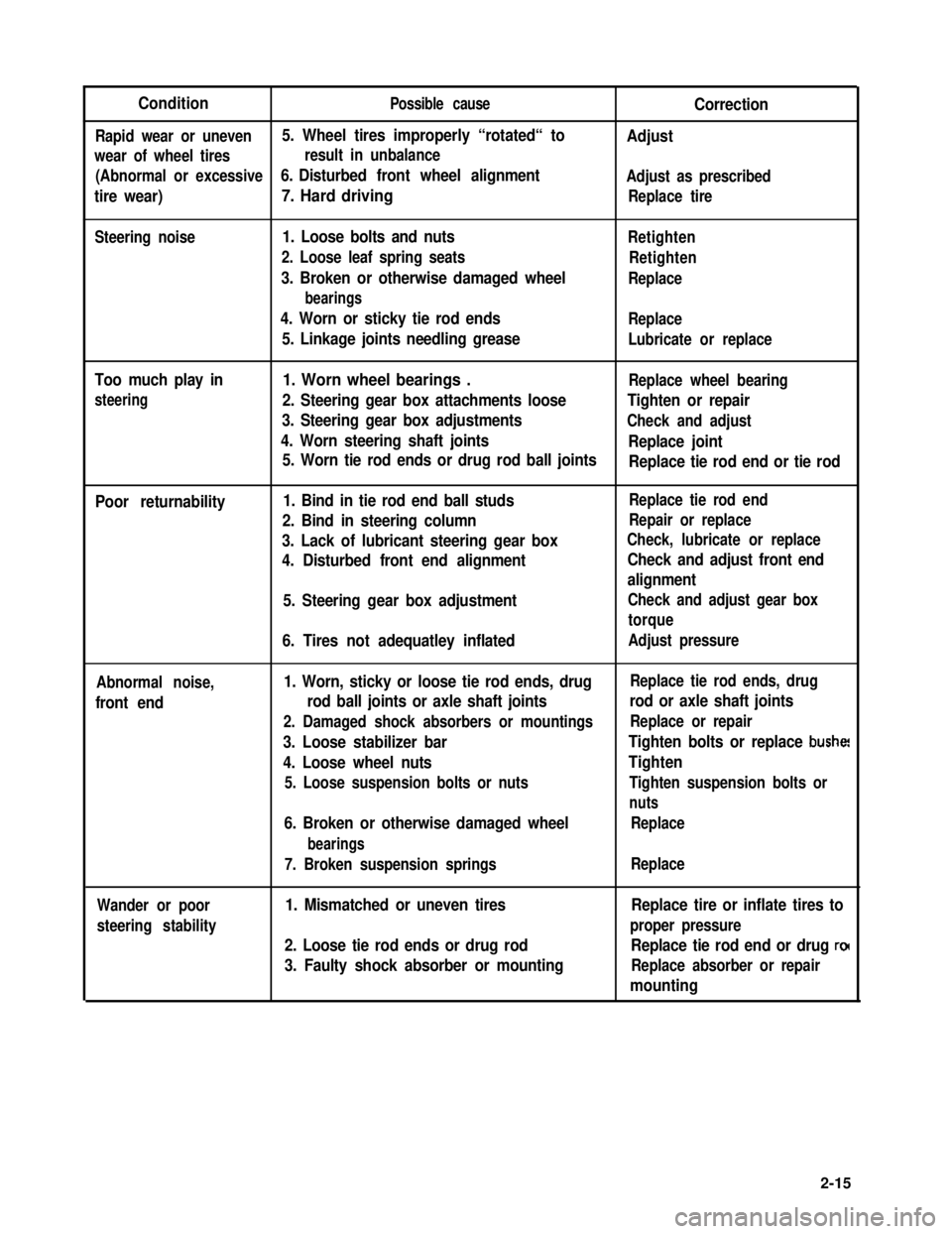
ConditionPossible causeCorrection
Rapid wear or uneven5. Wheel tires improperly “rotated“ toAdjust
wear of wheel tiresresult in unbalance
(Abnormal or excessive6. Disturbed front wheel alignmentAdjust as prescribed
tire wear)7. Hard drivingReplace tire
Steering noise1. Loose bolts and nuts
2. Loose leaf spring seats
3. Broken or otherwise damaged wheel
bearings
4. Worn or sticky tie rod ends
5. Linkage joints needling grease
Retighten
Retighten
Replace
Replace
Lubricate or replace
Too much play in
steering
1. Worn wheel bearings .Replace wheel bearing
2. Steering gear box attachments looseTighten or repair
3. Steering gear box adjustmentsCheck and adjust
4. Worn steering shaft jointsReplace joint
5. Worn tie rod ends or drug rod ball jointsReplace tie rod end or tie rod
Poor returnability1. Bind in tie rod end ball studs
2. Bind in steering column
3. Lack of lubricant steering gear box
4. Disturbed front end alignment
5. Steering gear box adjustment
6. Tires not adequatley inflated
Replace tie rod end
Repair or replace
Check, lubricate or replace
Check and adjust front end
alignment
Check and adjust gear box
torque
Adjust pressure
Abnormal noise,
front end
1. Worn, sticky or loose tie rod ends, drug
rod ball joints or axle shaft joints
2. Damaged shock absorbers or mountings
3. Loose stabilizer bar
4. Loose wheel nuts
5. Loose suspension bolts or nuts
6. Broken or otherwise damaged wheel
bearings
7. Broken suspension springs
Replace tie rod ends, drug
rod or axle shaft joints
Replace or repair
Tighten bolts or replace bushe!
Tighten
Tighten suspension bolts or
nuts
Replace
Replace
Wander or poor
steering stability
1. Mismatched or uneven tires
2. Loose tie rod ends or drug rod
3. Faulty shock absorber or mounting
Replace tire or inflate tires to
proper pressure
Replace tie rod end or drug ro(
Replace absorber or repair
mounting
2-15
Page 54 of 962
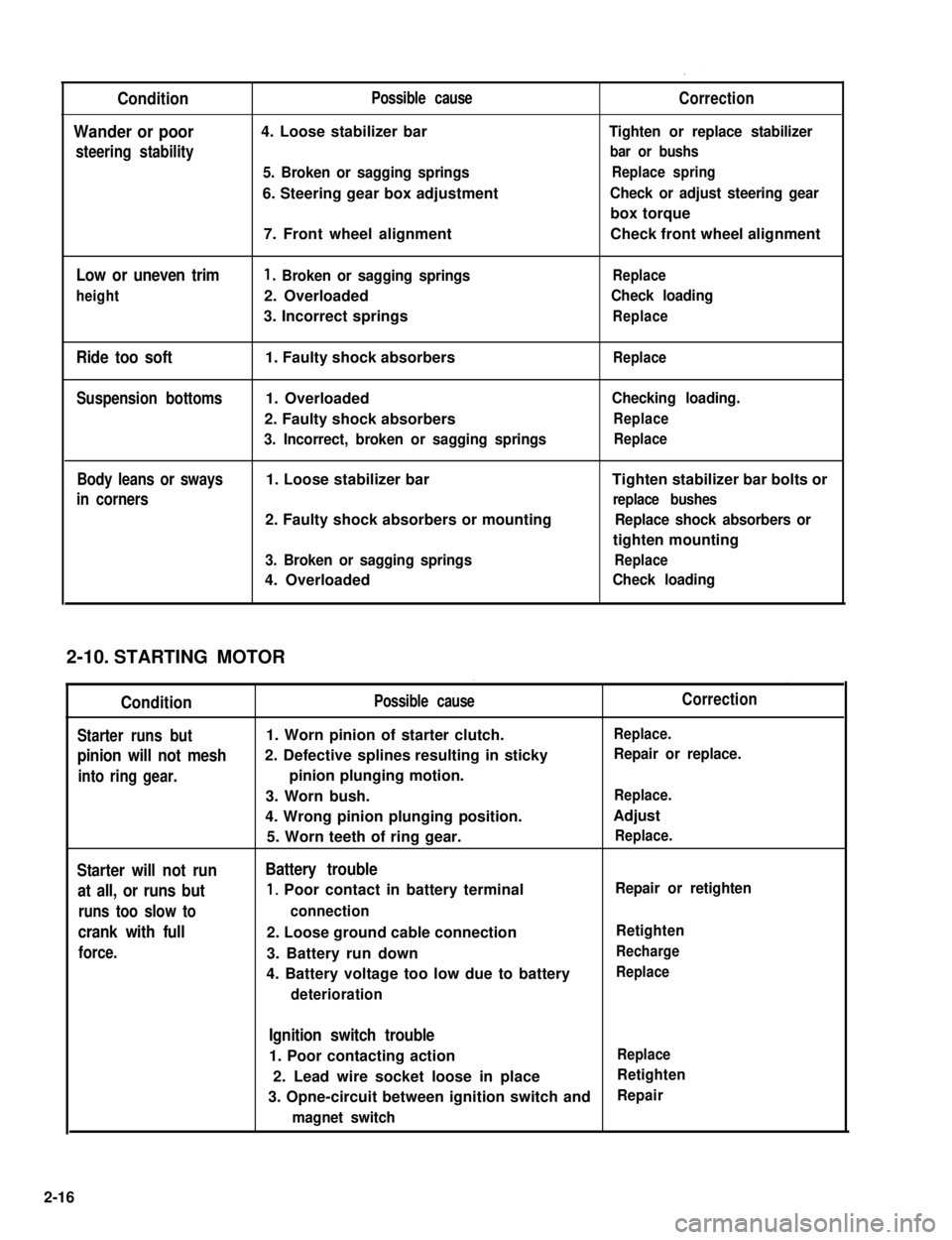
Condition
Wander or poor
steering stability
Low or uneven trim
height
Ride too soft
Suspension bottoms
Body leans or sways
in corners
Possible cause
4. Loose stabilizer bar
5. Broken or sagging springs
6. Steering gear box adjustment
7. Front wheel alignment
1. Broken or sagging springs
2. Overloaded
3. Incorrect springs
1. Faulty shock absorbers
1. Overloaded
2. Faulty shock absorbers
3. Incorrect, broken or sagging springs
1. Loose stabilizer bar
2. Faulty shock absorbers or mounting
3. Broken or sagging springs
4. Overloaded
Correction
Tighten or replace stabilizer
bar or bushs
Replace spring
Check or adjust steering gear
box torque
Check front wheel alignment
Replace
Check loading
Replace
Replace
Checking loading.
Replace
Replace
Tighten stabilizer bar bolts or
replace bushes
Replace shock absorbers or
tighten mounting
Replace
Check loading
STARTING MOTOR
Condition
Starter runs but
pinion will not mesh
into ring gear.
Starter will not run
at all, or runs but
runs too slow to
crank with full
force.
Possible cause
1. Worn pinion of starter clutch.
2. Defective splines resulting in sticky
pinion plunging motion.
3. Worn bush.
4. Wrong pinion plunging position.
5. Worn teeth of ring gear.
Battery trouble
1, Poor contact in battery terminal
connection
2. Loose ground cable connection
3. Battery run down
4. Battery voltage too low due to battery
deterioration
Correction
Replace.
Repair or replace.
Replace.
Adjust
Replace.
Repair or retighten
Retighten
Recharge
Replace
Ignition switch trouble
1. Poor contacting actionReplace
2. Lead wire socket loose in placeRetighten
3. Opne-circuit between ignition switch andRepair
magnet switch
2-10.
2-16
Page 66 of 962
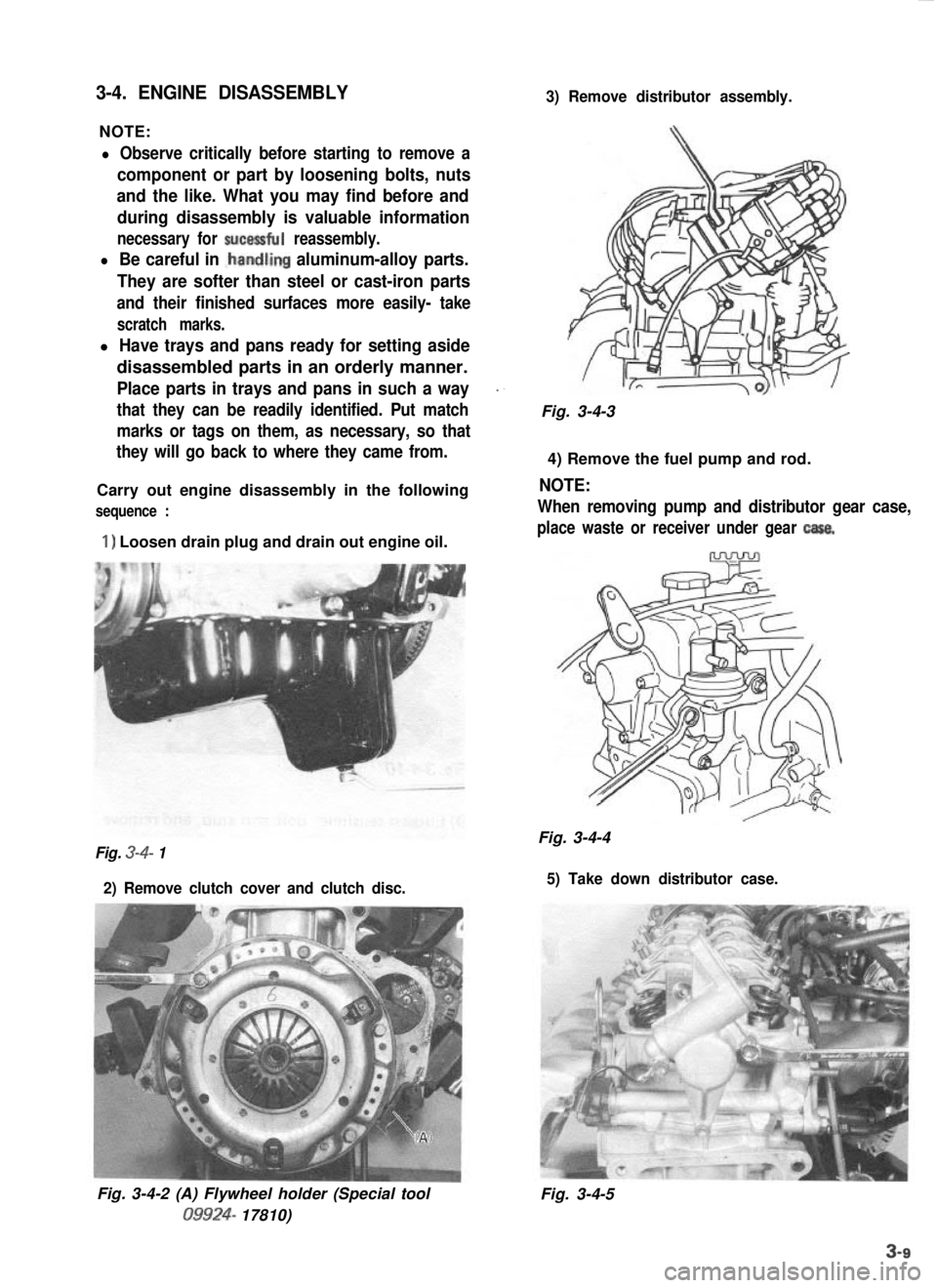
3-4. ENGINE DISASSEMBLY
NOTE:
3) Remove distributor assembly.
l Observe critically before starting to remove a
component or part by loosening bolts, nuts
and the like. What you may find before and
during disassembly is valuable information
necessary for sucessful reassembly.
l Be careful in .handling aluminum-alloy parts.
They are softer than steel or cast-iron parts
and their finished surfaces more easily- take
scratch marks.
l Have trays and pans ready for setting aside
disassembled parts in an orderly manner.
Place parts in trays and pans in such a way_.
that they can be readily identified. Put matchFig. 3-4-3
marks or tags on them, as necessary, so that
they will go back to where they came from.
4) Remove the fuel pump and rod.
Carry out engine disassembly in the following
NOTE:
sequence :When removing pump and distributor gear case,
1) Loosen drain plug and drain out engine oil.place waste or receiver under gear casa.
Fig. 3-4-4Fig. 3-4- 1
2) Remove clutch cover and clutch disc. 5) Take down distributor case.
Fig. 3-4-2 (A) Flywheel holder (Special tool09924-
17810) Fig. 3-4-5
Page 67 of 962
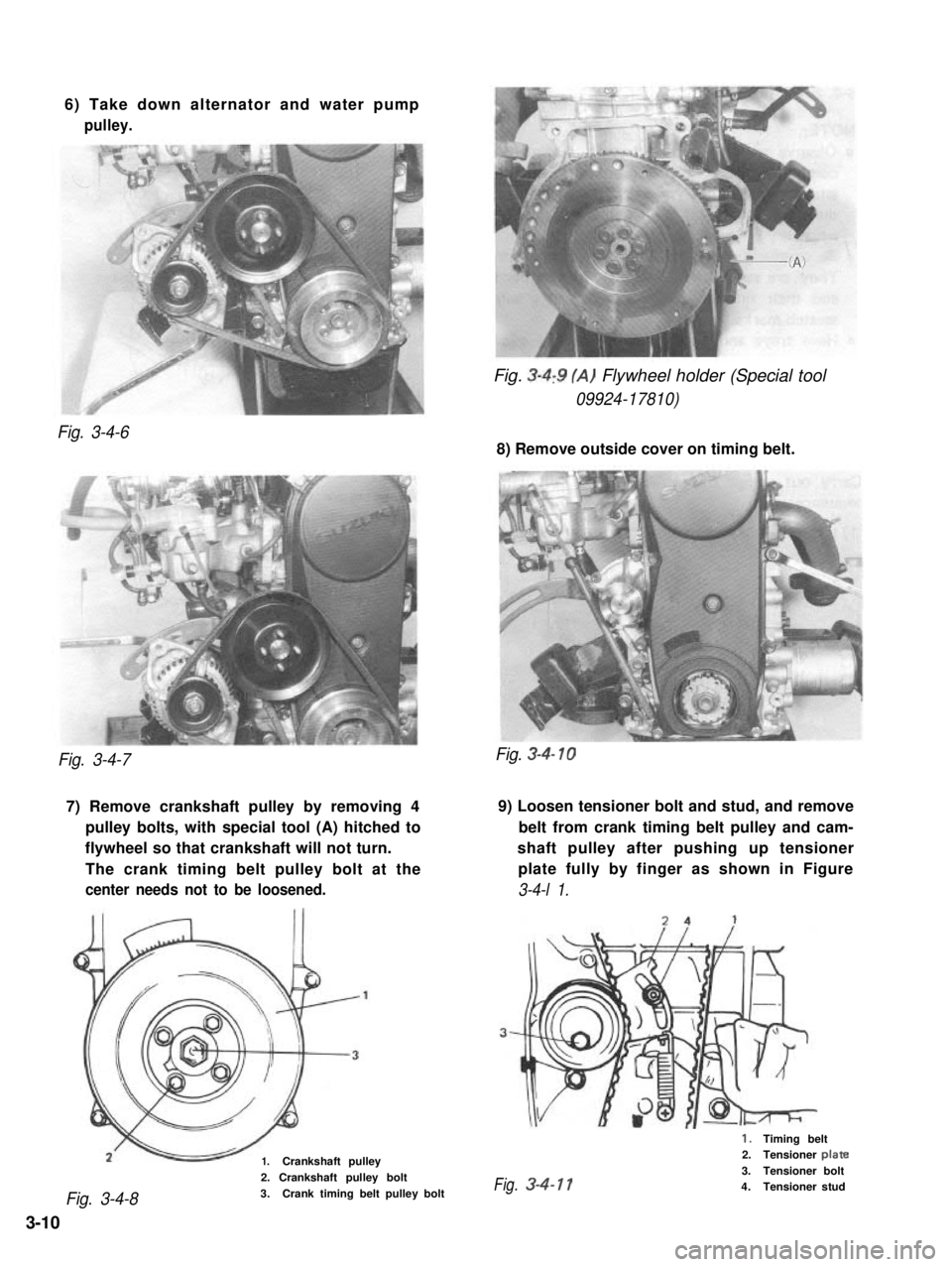
6) Take down alternator and water pump
pulley.
Fig. 3-4,9 (A) Flywheel holder (Special tool
09924-17810)
Fig. 3-4-6
8) Remove outside cover on timing belt.
Fig. 3-4-7
7) Remove crankshaft pulley by removing 49) Loosen tensioner bolt and stud, and remove
pulley bolts, with special tool (A) hitched tobelt from crank timing belt pulley and cam-
flywheel so that crankshaft will not turn.shaft pulley after pushing up tensioner
The crank timing belt pulley bolt at theplate fully by finger as shown in Figure
center needs not to be loosened.3-4-l 1.
1.Crankshaft pulley
Fig. 3-4-8
2. Crankshaft pulley bolt
3.Crank timing belt pulley bolt
Fig. 3-4- 10
1.Timing belt2.Tensioner plate
3.Tensioner boltFig.3-4-114.Tensioner stud
3-10