1987 SUZUKI GRAND VITARA warning light
[x] Cancel search: warning lightPage 51 of 962

Condition
Excessive pedal travel
(Pedal stroke too
large)
Possible cause
1. Partial brake system failure
2. Insufficient fluid in master
cylinder reservoirs
Correction
Check diagonal brake systems and
repair as necessary
Fill reservoirs with approved brake
fluid. Check for leaks and air in
brake systems. Check warning light.
Bleed system if necessary.
3. Air in system (Pedal soft/spongy)Bleed system
4. Rear brake system not adjustedAdjust rear brakes (Repair auto
(malfunctioning auto adjustingadjusting mechanism)
mechanism)
5. Bent brake shoesReplace brake shoes
6. Worn rear brake shoesReplace brake shoes.
Dragging brakes (A
very light drag is pre-
sent in all disc brakes
immediately after
pedal is released)
1. Master cylinder pistons not
returning correctly
2. Clogged return port in master
cylinder
3. Restricted brake tubes or hoses
4. Incorrect parking brake
adjustment
5. Weakened or broken return
springs in the brake
Repair master cylinder
Clean
Check for soft hoses or damaged tubes
and replace with new hoses and/or
new double-walled steel brake tubing
Check and adjust to correct specifica-
tions
Replace
6. Sluggish parking-brake cables or
linkage
Repair or replace
7. Wheel cylinder or caliper piston
sticking
Repair as necessary
Pedal pulsation1. Damaged or loose wheel bearingsReplace wheel bearings
(Pedal pulsates when2. Excessive disc lateral runout Check per instructions. If not within
depressed for braking)specifications, replace or machine the
disc.
3. Parallelism not within specifica-Check per instructions. If not within
tionsspecifications, replace or machine the
disc.
4. Rear drums out of roundCheck runout.
Braking noise1. Glazed shoe linings, or foreignRepair or replace shoe lining
matters stuck to linings
2. Worn or distorted shoe liningsReplace shoe lining (or pad)
3. Loose front wheel bearingsReplace wheel bearings
4. Distorted backing plates or looseReplace or retighten securing bolts
mounting bolts
2-13
Page 193 of 962
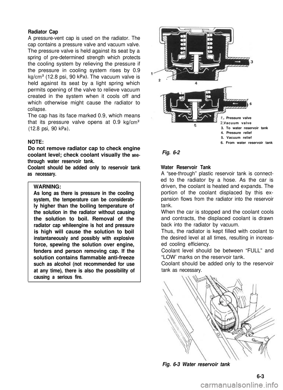
Radiator Cap
A pressure-vent cap is used on the radiator. The
cap contains a pressure valve and vacuum valve.
The pressure valve is held against its seat by a
spring of pre-determined strength which protects
the cooling system by relieving the pressure if
the pressure in cooling system rises by 0.9
kg/cm2 (12.8 psi, 90 kPa). The vacuum valve is
held against its seat by a light spring which
permits opening of the valve to relieve vacuum
created in the system when it cools off and
which otherwise might cause the radiator to
collapse.
The cap has its face marked 0.9, which means
that its pressure valve opens at 0.9 kg/cm2
(12.8 psi, 90 kPa).
NOTE:
Do not remove radiator cap to check engine
coolant level; check coolant visually the see-
through water reservoir tank.
Coolant should be added only to reservoir tank
as necessary.
4
WARNING:
As long as there is pressure in the cooling
system, the temperature can be considerab-
ly higher than the boiling temperature of
the solution in the radiator without causing
the solution to boil. Removal of the
radiator cap whileengine is hot and pressure
is high will cause the solution to boil
instantaneously and possibly with explosive
force, spewing the solution over engine,
fenders and person removing cap. If the
solution contains flammable anti-freeze
such as alcohol (not recommended for use
at any time), there is also the possibility of
causing a serious fire.
2’
I6
. Pressure valve
Vacuum valve
3. To water reservoir tank4. Pressure relief5. Vacuum relief
6. From water reservoir tank
Fig. 6-2
Water Reservoir Tank
A “see-through” plastic reservoir tank is connect-
ed to the radiator by a hose. As the car is
driven, the coolant is heated and expands. The
portion of the coolant displaced by this ex-
pansion flows from the radiator into the reservoir
tank.
When the car is stopped and the coolant cools
and contracts, the displaced coolant is drawn
back into the radiator by vacuum.
Thus, the radiator is kept filled with coolant to
the desired level at all times, resulting in increas-
ed cooling efficiency.
Coolant level should be between “FULL” and
“LOW’ marks on the reservoir tank.
Coolant should be added only to the reservoir
tank as necessary.
Fig. 6-3 Water reservoir tank
6-3
Page 208 of 962
![SUZUKI GRAND VITARA 1987 Service Repair Manual 7-4. REMOVAL AND INSTALLATION
Removal
[Heater and blower motor]
1. Disconnect battery negative cable.
2. Drain cooling system.
WARNING:
To help avoid the danger of being burned, do
not remove the drai SUZUKI GRAND VITARA 1987 Service Repair Manual 7-4. REMOVAL AND INSTALLATION
Removal
[Heater and blower motor]
1. Disconnect battery negative cable.
2. Drain cooling system.
WARNING:
To help avoid the danger of being burned, do
not remove the drai](/manual-img/20/57437/w960_57437-207.png)
7-4. REMOVAL AND INSTALLATION
Removal
[Heater and blower motor]
1. Disconnect battery negative cable.
2. Drain cooling system.
WARNING:
To help avoid the danger of being burned, do
not remove the drain plug and the radiator
cap while the engine and radiator are still hot.
Scalding fluid and steam can be blown out
under pressure if the plug and cap are taken
off too soon.
Fig 7-51. Drain plug2. Radiator
3. Disconnect heater inlet and outlet hoses
from heater unit pipes.
4. Remove instrument panel ass’y with speedo-
meter ass’y as follows.
1) Take off horn pad and remove steering
wheel using special tool @.
2) If equipped with radio and cigarette lighter,
disconnect radio and cigarette lighter lead
wires, and pull out radio case with radio
and cigarette lighter after loosening case
stay screw, and remove radio case bracket.
3) Pull out ashtray and loosen ashtray plate
screws.
4) Disconnect front food opening cable from
lock ass’y.
5) Loosen panel box stay screw and hood
opening cable lock nut on back side of
panel box cover.
6) Disconnect lead wires to control lever at
the coupler and heater control cables.
7) Pull out lever knobs and plate, and loosen
lever case screws.
8) Remove defroster and side ventilator hoses.
9) Disconnect lead wires to speedometer and
switches installed instrument panel at the
couplers.
10) Disconnect speedometer cable from speedo-
meter.
11) Release wire harness clamps installed to
instrument panel.
12) Loosen screws securing instrument panel.
13) Remove instrument panel.
NOTE:
l Before removing, recheck to ascertain all
hoses, wire harness, cables and screws are
disconnected from instrument paneL
l When removing heater lever case which is
fitted in steering column holder, be very
careful not to damage it
5. Remove steering column holder after loosen-
ing front door open stopper screws.
Fig. 7-7Fig. 7-6@ Special tool (Steering wheel
remover 09944-360 10)
7-5
Page 219 of 962
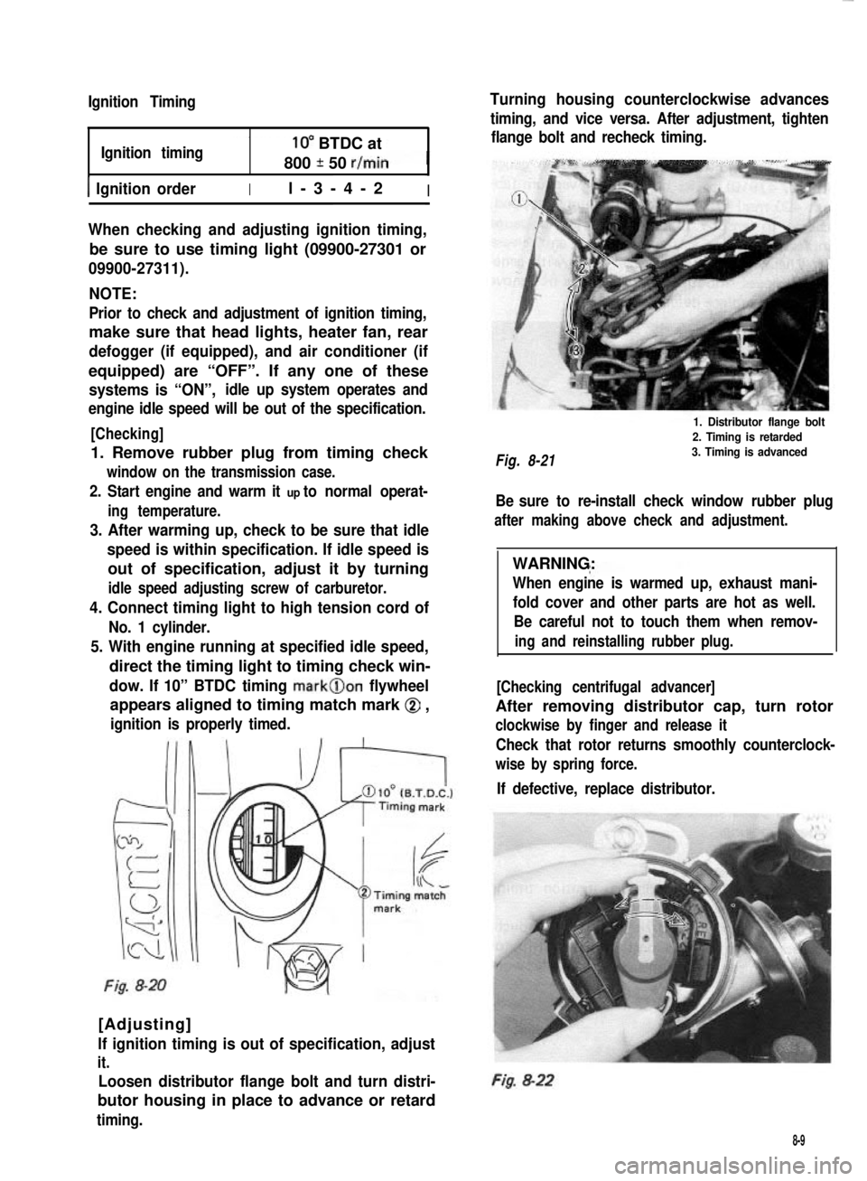
Ignition Timing
Ignition timing10” BTDC at
800 * 50 r/min
1 Ignition orderIl-3-4-2I
When checking and adjusting ignition timing,
be sure to use timing light (09900-27301 or
09900-27311).
NOTE:
Prior to check and adjustment of ignition timing,
make sure that head lights, heater fan, rear
defogger (if equipped), and air conditioner (if
equipped) are “OFF”. If any one of these
systems is “ON”,idle up system operates and
engine idle speed will be out of the specification.
[Checking]
1. Remove rubber plug from timing check
window on the transmission case.
2. Start engine and warm it up to normal operat-
ing temperature.
3. After warming up, check to be sure that idle
speed is within specification. If idle speed is
out of specification, adjust it by turning
idle speed adjusting screw of carburetor.
4. Connect timing light to high tension cord of
No. 1 cylinder.
5. With engine running at specified idle speed,
direct the timing light to timing check win-
dow. If 10” BTDC timing mark@on flywheel
appears aligned to timing match mark @ ,
ignition is properly timed.
Fig. 8-20
[Adjusting]
lf ignition timing is out of specification, adjust
it.
Loosen distributor flange bolt and turn distri-
butor housing in place to advance or retard
timing.
Turning housing counterclockwise advances
timing, and vice versa. After adjustment, tighten
flange bolt and recheck timing.
Fig. 8-21
1. Distributor flange bolt
2. Timing is retarded
3. Timing is advanced
Be sure to re-install check window rubber plug
after making above check and adjustment.
WARNING:
When engine is warmed up, exhaust mani-
fold cover and other parts are hot as well.
Be careful not to touch them when remov-
ing and reinstalling rubber plug.
[Checking centrifugal advancer]
After removing distributor cap, turn rotor
clockwise by finger and release it
Check that rotor returns smoothly counterclock-
wise by spring force.
If defective, replace distributor.
Fig. 8-22
8-9
Page 384 of 962
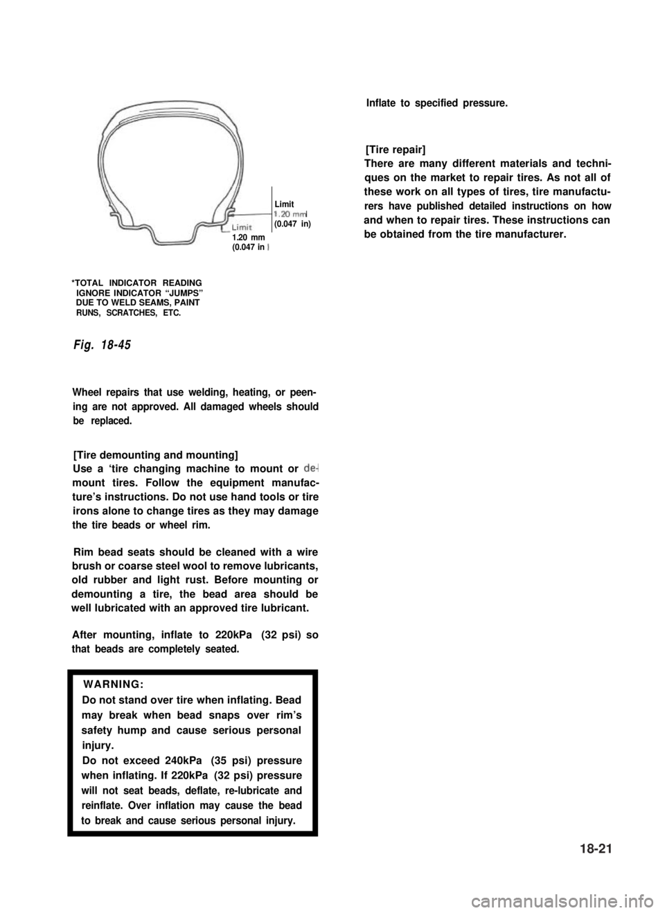
/I
d-
Limitl.Mmm(0.047 in)
1.20 mm(0.047 in 1
*TOTAL INDICATOR READINGIGNORE INDICATOR “JUMPS”DUE TO WELD SEAMS, PAINTRUNS, SCRATCHES, ETC.
Fig. 18-45
Wheel repairs that use welding, heating, or peen-
ing are not approved. All damaged wheels should
be replaced.
[Tire demounting and mounting]
Use a ‘tire changing machine to mount or de-
mount tires. Follow the equipment manufac-
ture’s instructions. Do not use hand tools or tire
irons alone to change tires as they may damage
the tire beads or wheel rim.
Rim bead seats should be cleaned with a wire
brush or coarse steel wool to remove lubricants,
old rubber and light rust. Before mounting or
demounting a tire, the bead area should be
well lubricated with an approved tire lubricant.
After mounting, inflate to 220kPa (32 psi) so
that beads are completely seated.
WARNING:
Do not stand over tire when inflating. Bead
may break when bead snaps over rim’s
safety hump and cause serious personal
injury.
Do not exceed 240kPa (35 psi) pressure
when inflating. If 220kPa (32 psi) pressure
will not seat beads, deflate, re-lubricate and
reinflate. Over inflation may cause the bead
to break and cause serious personal injury.1
Inflate to specified pressure.
[Tire repair]
There are many different materials and techni-
ques on the market to repair tires. As not all of
these work on all types of tires, tire manufactu-
rers have published detailed instructions on how
and when to repair tires. These instructions can
be obtained from the tire manufacturer.
18-21
Page 427 of 962
19-8. MAINTENANCE SERVICE
ROAD TESTING BRAKES
Brakes should be tested on dry, clean, smooth
and reasonably level roadway which is not
crowned. Road test brakes by making brake
applications with both light and heavy pedal
forces at various speeds to determine if the car
stops evenly and effectively.
Also drive car to see if it leads to one side or the
other without brake application. If it does,
check tire pressure, front end alignment and
front suspension attachments for looseness.
See diagnosis chart for other causes.
BRAKE FLUID LEAKS
Check master cylinder fluid levels. While a slight
drop in reservoir level does result from normal
lining wear, an abnormally low level indicates a
leak in the system.In such a case, check the
entire brake system for leakage. If even a slight
evidence of leakage is noted, the cause should be
corrected or defective parts should be replaced.
BRAKE FLUID LEVEL INSPECTION
Be sure to use particular brake fluid either as
marked on reservoir cap of that car or recom-
mended in owner’s manual which comes along
with that car.
Use of any other fluid is strictly prohibited.
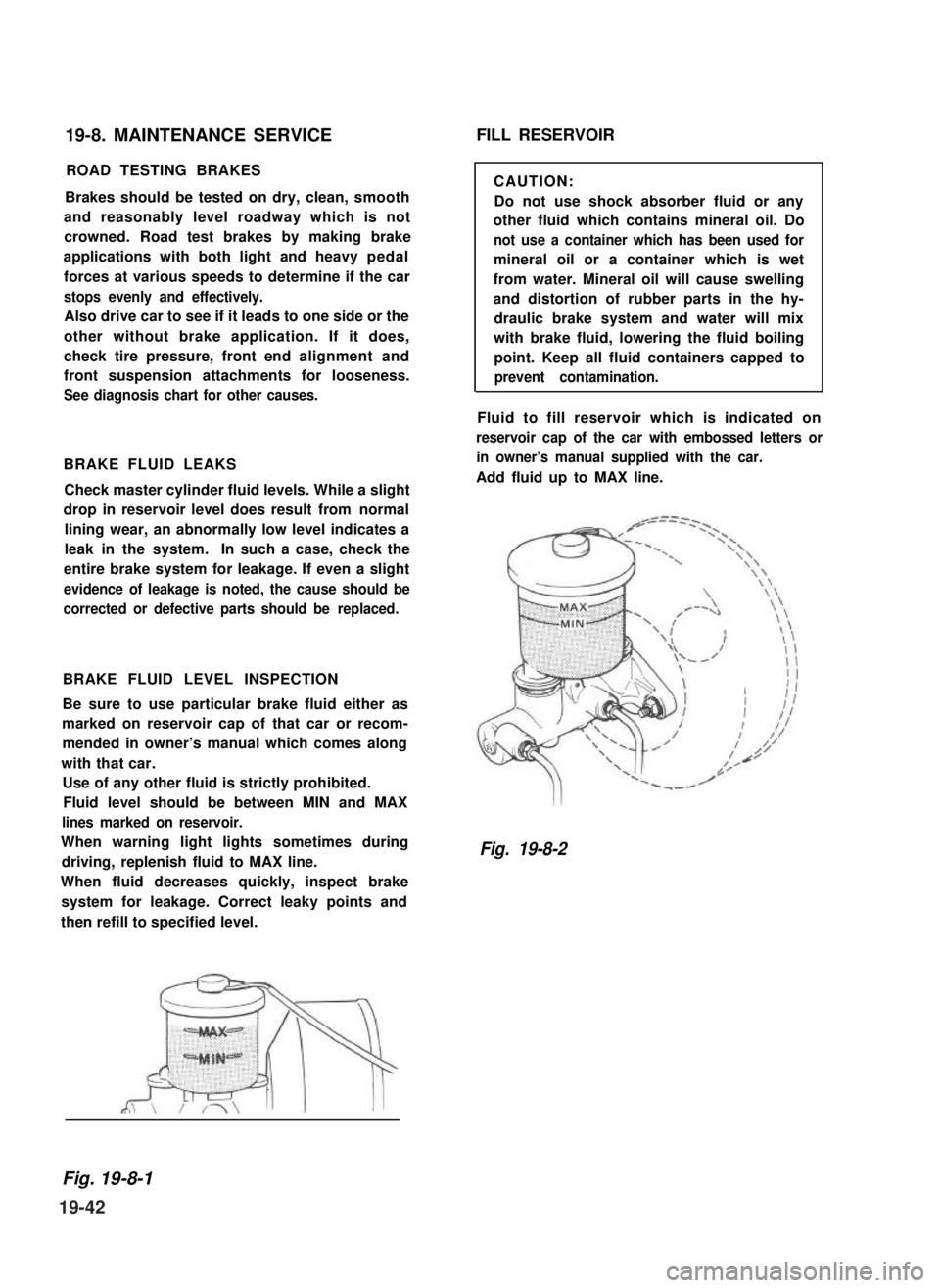
Fluid level should be between MIN and MAX
lines marked on reservoir.
When warning light lights sometimes during
driving, replenish fluid to MAX line.
When fluid decreases quickly, inspect brake
system for leakage. Correct leaky points and
then refill to specified level.
FILL RESERVOIR
CAUTION:
Do not use shock absorber fluid or any
other fluid which contains mineral oil. Do
not use a container which has been used for
mineral oil or a container which is wet
from water. Mineral oil will cause swelling
and distortion of rubber parts in the hy-
draulic brake system and water will mix
with brake fluid, lowering the fluid boiling
point. Keep all fluid containers capped to
prevent contamination.
Fluid to fill reservoir which is indicated on
reservoir cap of the car with embossed letters or
in owner’s manual supplied with the car.
Add fluid up to MAX line.
Fig. 19-8-2
Fig. 19-8-1
19-42
Page 448 of 962
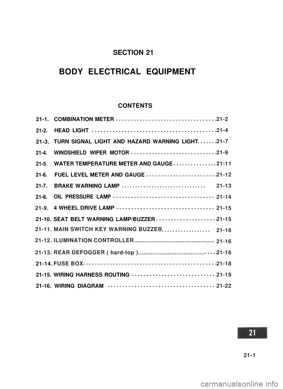
21-1.COMBINATION METER..................................
21-2.HEAD LIGHT..........................................
21-3.TURN SIGNAL LIGHT AND HAZARD WARNING LIGHT.......
21-4.WINDSHIELD WIPER MOTOR.............................
21-5.WATER TEMPERATURE METER AND GAUGE...............
21-6.FUEL LEVEL METER AND GAUGE........................
21-7.BRAKE WARNING LAMP ...............................
21-8.OIL PRESSURE LAMP..................................
4 WHEEL DRIVE LAMP.................................
21-10. SEAT BELT WARNING LAMP/BUZZER.....................
...................
...~I-I
.....
21-14. .............................................
21-15. WIRING HARNESS ROUTING............................
21-16. WIRING DIAGRAM....................................
SECTION 21
BODY ELECTRICAL EQUIPMENT
CONTENTS
21-9.
21-11. MAIN SWITCH KEY WARNING BUZZER
21-12. ILUMINATION CONTROLLER..............................................
21-13. REAR DEFOGGER ( hard-top )......................................
FUSE BOX
21-2
21-4
21-7
21-9
21-11
21-12
21-13
21-14
21-15
21-15
21-16
21-16
21-16
21-18
21-19
21-22
21-1
Page 450 of 962
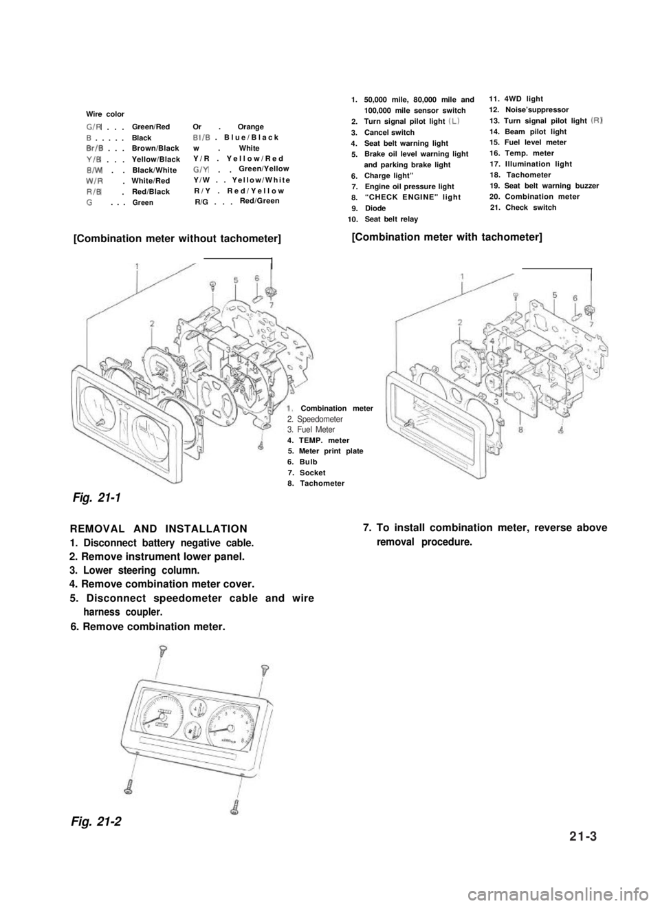
Wire color
G/R . . .Green/RedOr . Orange
0 . . . . .BlackBI/B . Blue/Black
0rlB . . .Brown/Blackw . White
Y/B . . .Yellow/BlackY/R . Yellow/Red
B/W . .Black/WhiteG/Y . .Green/Yellow
W/R .White/RedY/W . . Yellow/White
RIB .Red/BlackR/Y . Red/Yellow
G. . .GreenR/G . . .Red/Green
1.
2.
3.
4.
5.
6.7.
8.
9.
10.
50,000 mile, 80,000 mile and11. 4WD light
100,000 mile sensor switch12. Noise’suppressor
Turn signal pilot light (Lb13. Turn signal pilot light (RI
Cancel switch14. Beam pilot light
Seat belt warning light15. Fuel level meter
Brake oil level warning light16. Temp. meter
and parking brake light17. Illumination light
Charge light”18. Tachometer
Engine oil pressure light19. Seat belt warning buzzer
“CHECK ENGINE" light 20. Combination meter
Diode21. Check switch
Seat belt relay
[Combination meter without tachometer][Combination meter with tachometer]
4. TEMP. meter5. Meter print plate
6. Bulb
7. Socket
Combination meter
Fig. 21-1
8. Tachometer
REMOVAL AND INSTALLATION
1. Disconnect battery negative cable.
2. Remove instrument lower panel.
3. Lower steering column.
4. Remove combination meter cover.
5. Disconnect speedometer cable and wire
harness coupler.
7. To install combination meter, reverse above
removal procedure.
6. Remove combination meter.
Fig. 21-2
2. Speedometer3. Fuel Meter
21-3