1987 SUZUKI GRAND VITARA tires
[x] Cancel search: tiresPage 5 of 962
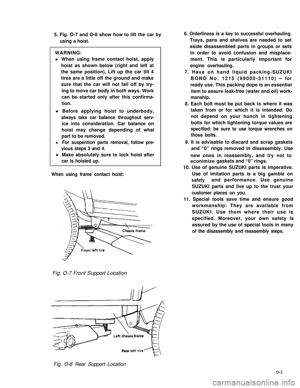
5. Fig. O-7 and O-8 show how to lift the car by
using a hoist.
WARNING:
l When using frame contact hoist, apply
hoist as shown below (right and left at
the same position), Lift up the car till 4
tires are a little off the ground and make
sure that the car will not fall off by try-
ing to move car body in both ways. Work
can be started only after this confirma-
tion.
l Before applying hoist to underbody,
always take car balance throughout serv-
ice into consideration. Car balance on
hoist may change depending of what
part to be removed.
lFor suspention parts removal, follow pre-
vious steps 3 and 4.
l Make absolutely sure to lock hoist after
car is hoisted up.
When using frame contact hoist:
6. Orderliness is a key to successful overhauling.
Trays, pans and shelves are needed to set
aside disassembled parts in groups or sets
in order to avoid confusion and misplace-
ment. This is particularly important for
engine overhauling.
7. Have on hand liquid packing-SUZUKI
BOND No. 1215 (99000-31110) - for
ready use. This packing dope is an essential
item to assure leak-free (water and oil) work-
manship.
8. Each bolt must be put back to where it was
taken from or for which it is intended. Do
not depend on your hunch in tightening
bolts for which tightening torque values are
specified: be sure to use torque wrenches on
those bolts.
9. It is advisable to discard and scrap gaskets
and “0” rings removed in disassembly. Use
new ones in reassembly, and try not to
econimize gaskets and “0” rings.
10. Use of genuine SUZUKI parts is imperative.
Use of imitation parts is a big gamble on
safetyand performance. Use genuine
SUZUKI parts and live up to the trust your
customer places on you.
11. Special tools save time and ensure good
workmanship: They are available from
SUZUKI. Use them where their use is
specified. Moreover, your own safety is
assured by the use of special tools in many
of the disassembly and reassembly steps.
Fig. O-7 Front Support Location
Fig. O-8 Rear Support Location
0-3
Page 34 of 962
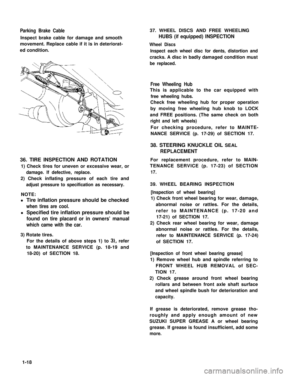
Parking Brake Cable
Inspect brake cable for damage and smooth
movement. Replace cable if it is in deteriorat-
ed condition.
36. TIRE INSPECTION AND ROTATION
1) Check tires for uneven or excessive wear, or
damage. If defective, replace.
2) Check inflating pressure of each tire and
adjust pressure to specification as necessary.
NOTE:
l Tire inflation pressure should be checked
when tires are cool.
l Specified tire inflation pressure should be
found on tire placard or in owners’ manual
which came with the car.
3) Rotate tires.
For the details of above steps 1) to 3), refer
to MAINTENANCE SERVICE (p. 18-19 and
18-20) of SECTION 18.
37. WHEEL DISCS AND FREE WHEELING
HUBS (if equipped) INSPECTION
Wheel Discs
Inspect each wheel disc for dents, distortion and
cracks. A disc in badly damaged condition must
be replaced.
Free Wheeling Hub
This is applicable to the car equipped with
free wheeling hubs.
Check free wheeling hub for proper operation
by moving free wheeling hub knob to LOCK
and FREE positions. (The same check on both
right and left wheels)
For checking procedure, refer to MAINTE-
NANCE SERVICE (p. 17-29) of SECTION 17.
38. STEERING KNUCKLE OIL SEAL
REPLACEMENT
For replacement procedure, refer to MAIN-
TENANCE SERVICE (p. 17-23) of SECTION
17.
39. WHEEL BEARING INSPECTION
[Inspection of wheel bearing]
1) Check front wheel bearing for wear, damage,
abnormal noise or rattles. For the details,
refer to MAINTENANCE (p. 17-20 and
17-21) of SECTION 17.
2) Check rear wheel bearing for wear, damage
abnormal noise or rattles. For the details,
refer to MAINTENANCE SERVICE (p. 17-24)
of SECTION 17.
[Inspection of front wheel bearing grease]
1) Remove wheel hub and spindle referring to
FRONT WHEEL HUB REMOVAL of SEC-
TION 17.
2) Check grease around front wheel bearing
rollars and between front axle shaft surface
and wheel spindle bush for deterioration and
capacity.
If grease is deteriorated, remove grease tho-
roughly and apply enough amount of new
SUZUKI SUPER GREASE A or wheel bearing
grease. If grease is found insufficient, add some
more.
1-18
Page 39 of 962

2-1.
2-2.
2-3.
2-4.
2-5.
2-6.
2-7.
2-6.
2-9.
SECTION 2
TROUBLE SHOOTING
CONTENTS
ENGINE...................................................2-2
CARBURETOR...........................................
EXHAUST AND MUFFLER.................................
CLUTCH.................................................2-9
TRANSMISSION..........................................
DIFFERENTIALS.........................................2-11
PROPELLER SHAFTS.....................................2-12
BRAKES.............................................. 2-12
SUSPENSION, STEERING SYSTEM AND TIRES................
STARTING MOTOR.....................................
2-11. ALTERNATOR...........................................
FUEL METER............................................ 2-19
2-14. SPEEDOMETER..........................................2-19
2-15. WATER TEMPERATURE METER.............................2-19
2-9
2-9
2-10
2-14
2-16
2-17
2-18WIPER MOTOR.......................................
2-10.
2-12.
2-13.
2-1
2
Page 50 of 962
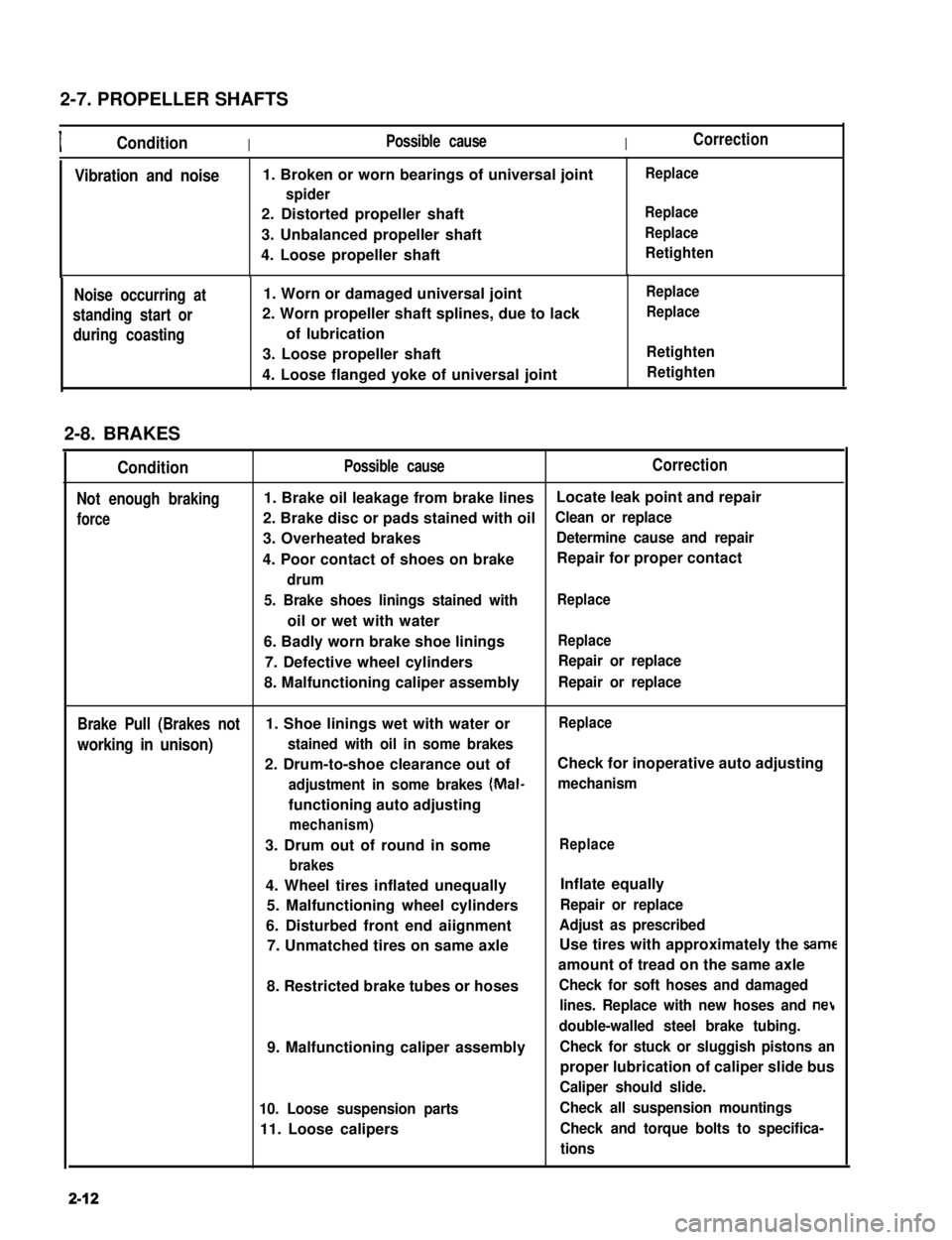
2-7. PROPELLER SHAFTS
IConditionIPossible causeICorrection
Vibration and noise1. Broken or worn bearings of universal joint
spider
2. Distorted propeller shaft
3. Unbalanced propeller shaft
4. Loose propeller shaft
Replace
Replace
Replace
Retighten
Noise occurring at
standing start or
during coasting
1. Worn or damaged universal joint
2. Worn propeller shaft splines, due to lack
of lubrication
3. Loose propeller shaft
4. Loose flanged yoke of universal joint
Replace
Replace
Retighten
Retighten
2-8. BRAKES
Condition
Not enough braking
force
Possible causeCorrection
1. Brake oil leakage from brake linesLocate leak point and repair
2. Brake disc or pads stained with oilClean or replace
3. Overheated brakesDetermine cause and repair
4. Poor contact of shoes on brakeRepair for proper contact
drum
5. Brake shoes linings stained with
oil or wet with water
Replace
6. Badly worn brake shoe liningsReplace
7. Defective wheel cylindersRepair or replace
8. Malfunctioning caliper assemblyRepair or replace
Brake Pull (Brakes not1. Shoe linings wet with water orReplace
working in unison)stained with oil in some brakes
2. Drum-to-shoe clearance out ofCheck for inoperative auto adjusting
adjustment in some brakes (Mal-mechanism
functioning auto adjusting
mechanism)
3. Drum out of round in some
brakes
Replace
4. Wheel tires inflated unequally
5. Malfunctioning wheel cylinders
6. Disturbed front end aiignment
7. Unmatched tires on same axle
8. Restricted brake tubes or hoses
9. Malfunctioning caliper assembly
10. Loose suspension parts
11. Loose calipers
Inflate equally
Repair or replace
Adjust as prescribed
Use tires with approximately the same
amount of tread on the same axle
Check for soft hoses and damaged
lines. Replace with new hoses and net
double-walled steel brake tubing.
Check for stuck or sluggish pistons an
proper lubrication of caliper slide bus
Caliper should slide.
Check all suspension mountings
Check and torque bolts to specifica-
tions
2-12
Page 52 of 962

2-9. SUSPENSION, STEERING SYSTEM AND TIRES
Condition
Hard steering
Possible causeCorrection
1. Wheel tires not adequately inflatedAdjust the pressure
2. Bind in tie rod end ball studReplace
3. Linkage connections tending to seizeRepair or replace
4. Steering gearbox out of adjustmentAdjust as prescribed
5. Unevenly worn steering shaft bushReplace
6. Disturbed front wheel alignmentAdjust as prescribed
Wobbly steering wheel1. Wheel tires inflated unequallyAdjust tire pressure
(Shimmy, shake or2. Wobbly wheelsRepair or replace
vibration)3. Large difference in tire diameter betweenReplace._
right and left wheels
4. Loose hub nutsRetighten
5. Damaged or worn wheel bearingsReplace
6. Worn or loose tie rod endsReplace or retighten
7. Steering gearbox out of adjustmentAdjust as prescribed
8. Steering gearbox mounted looseRetighten
9. Worn steering knuckle oil sealReplace
10. Tire or wheel out of balanceBalance wheel or replace tire
and/or wheel
11. Blister or bump on tireReplace tire
12. Disturbed front wheel alignmentCheck front wheel alignment
Steering wheel
pulling to one
side (car pulls)
1. Unevenly worn wheel tires
2. Brake dragging in one road wheel
3. Wheel tires unequally inflated
4. Worn or distorted link rods
5. Disturbed front wheel alignment
6. Loose, bent or broken front or rear
suspension parts
Replace
Repair
Adjust tire pressure
Replace
Adjust as prescribed
Tighten or replace suspension
parts
Shocks coming to1. Tire inflating pressure too highReduce to the specification
steering wheel2. Poor shock absorber performanceReplace
(or wheel tramp)3. Differences in tire diameter among fourAdjust
road wheels
4. Worn steering linkage connectionsReplace
5. Worn or broken front wheel bearingsReplace
6. Loose front wheelRetighten
7. Steering wheel loose in placeRetighten the nut
8. Blister or bump on tireReplace tire
Rapid wear or uneven1. Wheel tires imporperly inflatedAdjust tire pressure
wear of wheel tires2. Differences in diameter among four tiresAdjust or replace
(Abnormal or excessive3. Worn or loose road wheel bearingsReplace
tire wear)4. Wobbly wheel tiresRepair or replace
2-14
Page 53 of 962
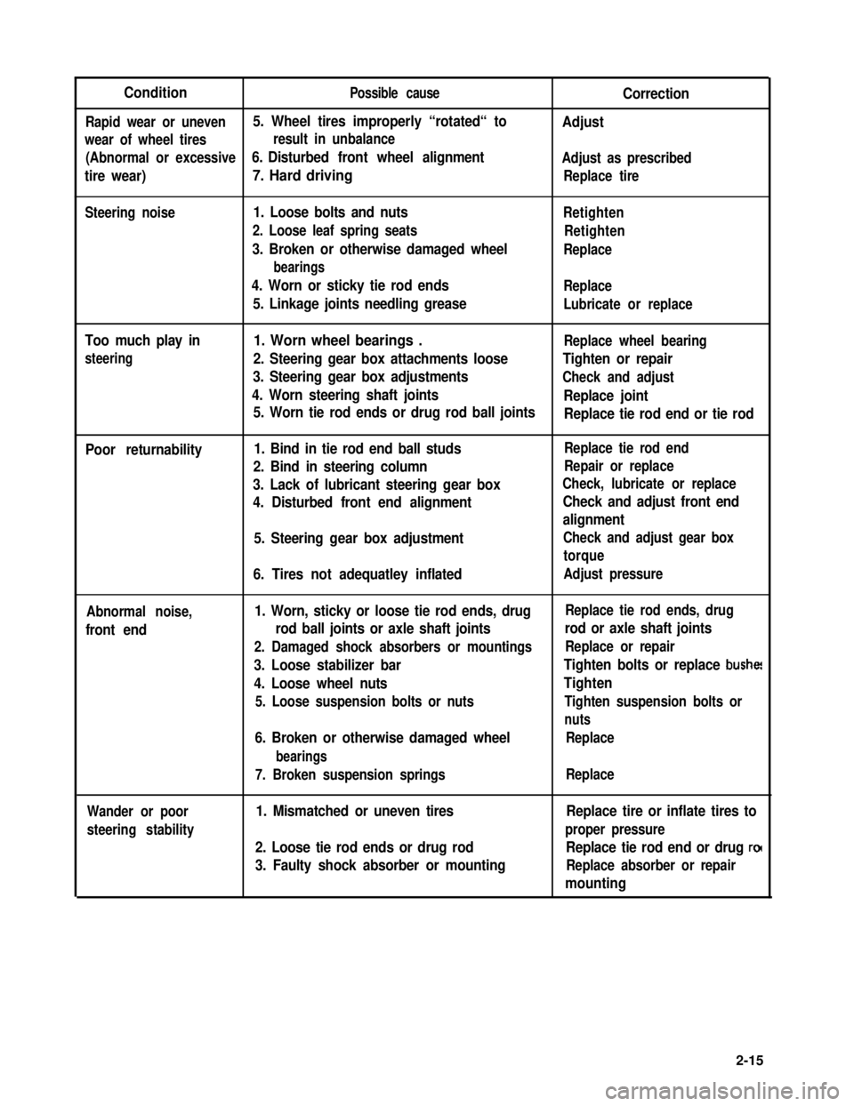
ConditionPossible causeCorrection
Rapid wear or uneven5. Wheel tires improperly “rotated“ toAdjust
wear of wheel tiresresult in unbalance
(Abnormal or excessive6. Disturbed front wheel alignmentAdjust as prescribed
tire wear)7. Hard drivingReplace tire
Steering noise1. Loose bolts and nuts
2. Loose leaf spring seats
3. Broken or otherwise damaged wheel
bearings
4. Worn or sticky tie rod ends
5. Linkage joints needling grease
Retighten
Retighten
Replace
Replace
Lubricate or replace
Too much play in
steering
1. Worn wheel bearings .Replace wheel bearing
2. Steering gear box attachments looseTighten or repair
3. Steering gear box adjustmentsCheck and adjust
4. Worn steering shaft jointsReplace joint
5. Worn tie rod ends or drug rod ball jointsReplace tie rod end or tie rod
Poor returnability1. Bind in tie rod end ball studs
2. Bind in steering column
3. Lack of lubricant steering gear box
4. Disturbed front end alignment
5. Steering gear box adjustment
6. Tires not adequatley inflated
Replace tie rod end
Repair or replace
Check, lubricate or replace
Check and adjust front end
alignment
Check and adjust gear box
torque
Adjust pressure
Abnormal noise,
front end
1. Worn, sticky or loose tie rod ends, drug
rod ball joints or axle shaft joints
2. Damaged shock absorbers or mountings
3. Loose stabilizer bar
4. Loose wheel nuts
5. Loose suspension bolts or nuts
6. Broken or otherwise damaged wheel
bearings
7. Broken suspension springs
Replace tie rod ends, drug
rod or axle shaft joints
Replace or repair
Tighten bolts or replace bushe!
Tighten
Tighten suspension bolts or
nuts
Replace
Replace
Wander or poor
steering stability
1. Mismatched or uneven tires
2. Loose tie rod ends or drug rod
3. Faulty shock absorber or mounting
Replace tire or inflate tires to
proper pressure
Replace tie rod end or drug ro(
Replace absorber or repair
mounting
2-15
Page 380 of 962
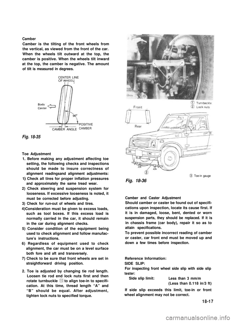
Camber
Camber is the tilting of the front wheels from
the vertical, as viewed from the front of the car.
When the wheels tilt outward at the top, the
camber is positive. When the wheels tilt inward
at the top, the camber is negative. The amount
of tilt is measured in degrees.
CENTER LINEOF yH,EEL
Fig. 18-35
CAMBER ANGLE
‘POSITIVE
CAMBER
Toe Adjustment
1. Before making any adjustment affecting toe
setting, the following checks and inspections
should be made to insure correctness of
alignment readingsand alignment adjustments:
1) Check all tires for proper inflation pressures
and approximately the same tread wear.
2) Check steering and suspension system for
looseness. If excessive looseness is noted, it
must be corrected before adjusting.
3) Check for run-out of wheels and tires.
4)Consideration must be given to excess loads,
such as tool boxes. If this excess load is
normally carried in the car, it should remain
in the car during alignment checks.
5) Consider condition of the equipment being
used to check alignment and follow manufac-
ture’s instructions.
6) Regardless of equipment used to check
alignment, the car must be on a level surface
both fore and aft and transversely.
7) Check to be sure that front wheels are set in
straightforward driving position.
2. Toe is adjusted by changing tie rod length.
Loosen tie rod end lock nuts first and then
rotate turnbuckle @ to align toe-in to specifi-
cation. At this time, thread length “A” and
“B” should be equal. After adjustment,
tighten lock nuts to specified torque.
@ Toe-in gauge
Fig. 18-36
Camber and Caster Adjustment
Should camber or caster be found out of specifi-
cations upon inspection, locate its cause first. If
it is in damaged, loose, bent, dented or worn
suspension parts, they should be replaced. If it is
in chassis frame (car body), repair it so as to
attain specifications.
To prevent possible incorrect reading of camber
or caster, car front end must be moved up and
down a few times before inspection.
Reference Information:
SIDE SLIP:
For inspecting front wheel side slip with side slip
tester:
Side slip limit:Less than 3 mm/m
(Less than 0.118 in/3 ft)
If side slip exceeds this limit, toe-in or front
wheel alignment may not be correct.
18-17
Page 382 of 962
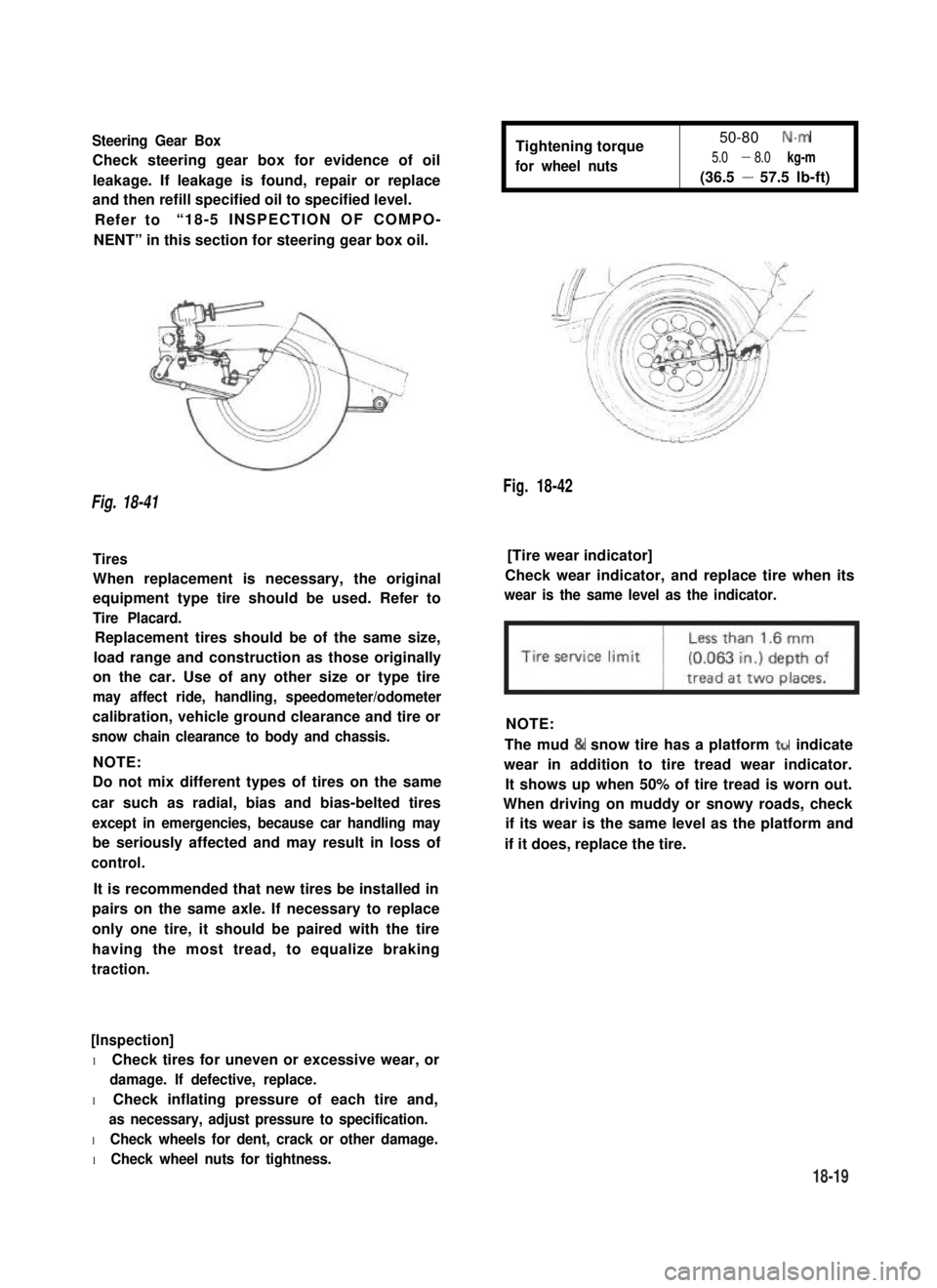
Steering Gear Box
Check steering gear box for evidence of oil
leakage. If leakage is found, repair or replace
and then refill specified oil to specified level.
Refer to“18-5 INSPECTION OF COMPO-
NENT” in this section for steering gear box oil.
Tightening torque
for wheel nuts
50-80 N.m
5.0 - 8.0 kg-m
(36.5 - 57.5 lb-ft)
Fig. 18-42
Fig. 18-41
Tires[Tire wear indicator]
When replacement is necessary, the original
equipment type tire should be used. Refer to
Tire Placard.
Check wear indicator, and replace tire when its
wear is the same level as the indicator.
Replacement tires should be of the same size,
load range and construction as those originally
on the car. Use of any other size or type tire
may affect ride, handling, speedometer/odometer
calibration, vehicle ground clearance and tire or
snow chain clearance to body and chassis.
NOTE:
NOTE:
Do not mix different types of tires on the same
car such as radial, bias and bias-belted tires
except in emergencies, because car handling may
be seriously affected and may result in loss of
control.
The mud & snow tire has a platform ttr indicate
wear in addition to tire tread wear indicator.
It shows up when 50% of tire tread is worn out.
When driving on muddy or snowy roads, check
if its wear is the same level as the platform and
if it does, replace the tire.
It is recommended that new tires be installed in
pairs on the same axle. If necessary to replace
only one tire, it should be paired with the tire
having the most tread, to equalize braking
traction.
[Inspection]
l Check tires for uneven or excessive wear, or
damage. If defective, replace.
l Check inflating pressure of each tire and,
as necessary, adjust pressure to specification.
l Check wheels for dent, crack or other damage.
l Check wheel nuts for tightness.
18-19