1987 SUZUKI GRAND VITARA front wheel bearings
[x] Cancel search: front wheel bearingsPage 48 of 962
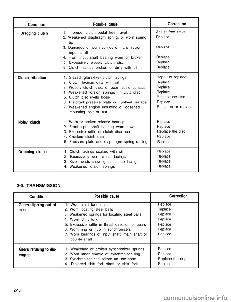
Condition
Clutch vibration
Noisy clutch
Grabbing clutch
2-5. TRANSMISSION
Condition
Gears slipping out of
mesh
Gears refusing to dis-
engage
Possible cause
1. Improper clutch pedal free travel
2. Weakened diaphragm spring, or worn spring
tip
3. Damaged or worn splines of transmission
input shaft
4. Front input shaft bearing worn or broken
5. Excessively wobbly clutch disc
6. Clutch facings broken or dirty with oil
1. Glazed (glass-like) clutch facings
2. Clutch facings dirty with oil
3. Wobbly clutch disc, or poor facing contact
4. Weakened torsion springs (in clutchdisc)
5. Clutch disc rivets loose
6. Distorted pressure plate or flywheel surface
7. Weakened engine mounting or loosened
mounting bolt or nut
1. Worn or broken release bearing
2. Front input shaft bearing worn down
3. Excessive rattle of clutch disc hub
4. Cracked clutch disc
5. Pressure plate and diaphragm spring rattling
1. Clutch facings soaked with oil
2. Excessively worn clutch facings
3. Rivet heads showing out of the facing
4. Weakened torsion springs
Possible cause
1. Worn shift fork shaft
2. Worn locating steel balls
3. Weakened springs for locating steel balls
4. Worn shift fork
5. Excessive rattle in thrust direction of gears
6. Worn ring or hub in synchronizers
7. Worn bearings of input shaft, main shaft or
countershaft
1. Weakened or broken synchronizer springs
2. Worn inner groove of synchronizer ring
3. Synchronizer ring seized on. the cone
4.Distorted shift fork shaft or shift fork
Correction
Adjust free travel
Replace
Replace
Replace
Replace
Replace
Repair or replace
Replace
Replace
Replace
Replace the disc
Replace
Retighten or replace
Replace
Replace
Replace the disc
Replace
Replace
Replace
Replace
Replace
Replace
Correction
Replace
Replace
Replace
Replace
Replace
Replace
Replace
Replace
Replace
Replace the ring
Replace.
Dragging clutch
2-10
Page 50 of 962
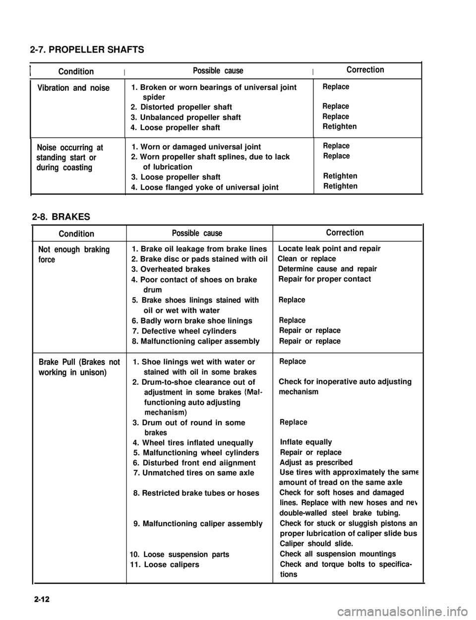
2-7. PROPELLER SHAFTS
IConditionIPossible causeICorrection
Vibration and noise1. Broken or worn bearings of universal joint
spider
2. Distorted propeller shaft
3. Unbalanced propeller shaft
4. Loose propeller shaft
Replace
Replace
Replace
Retighten
Noise occurring at
standing start or
during coasting
1. Worn or damaged universal joint
2. Worn propeller shaft splines, due to lack
of lubrication
3. Loose propeller shaft
4. Loose flanged yoke of universal joint
Replace
Replace
Retighten
Retighten
2-8. BRAKES
Condition
Not enough braking
force
Possible causeCorrection
1. Brake oil leakage from brake linesLocate leak point and repair
2. Brake disc or pads stained with oilClean or replace
3. Overheated brakesDetermine cause and repair
4. Poor contact of shoes on brakeRepair for proper contact
drum
5. Brake shoes linings stained with
oil or wet with water
Replace
6. Badly worn brake shoe liningsReplace
7. Defective wheel cylindersRepair or replace
8. Malfunctioning caliper assemblyRepair or replace
Brake Pull (Brakes not1. Shoe linings wet with water orReplace
working in unison)stained with oil in some brakes
2. Drum-to-shoe clearance out ofCheck for inoperative auto adjusting
adjustment in some brakes (Mal-mechanism
functioning auto adjusting
mechanism)
3. Drum out of round in some
brakes
Replace
4. Wheel tires inflated unequally
5. Malfunctioning wheel cylinders
6. Disturbed front end aiignment
7. Unmatched tires on same axle
8. Restricted brake tubes or hoses
9. Malfunctioning caliper assembly
10. Loose suspension parts
11. Loose calipers
Inflate equally
Repair or replace
Adjust as prescribed
Use tires with approximately the same
amount of tread on the same axle
Check for soft hoses and damaged
lines. Replace with new hoses and net
double-walled steel brake tubing.
Check for stuck or sluggish pistons an
proper lubrication of caliper slide bus
Caliper should slide.
Check all suspension mountings
Check and torque bolts to specifica-
tions
2-12
Page 51 of 962

Condition
Excessive pedal travel
(Pedal stroke too
large)
Possible cause
1. Partial brake system failure
2. Insufficient fluid in master
cylinder reservoirs
Correction
Check diagonal brake systems and
repair as necessary
Fill reservoirs with approved brake
fluid. Check for leaks and air in
brake systems. Check warning light.
Bleed system if necessary.
3. Air in system (Pedal soft/spongy)Bleed system
4. Rear brake system not adjustedAdjust rear brakes (Repair auto
(malfunctioning auto adjustingadjusting mechanism)
mechanism)
5. Bent brake shoesReplace brake shoes
6. Worn rear brake shoesReplace brake shoes.
Dragging brakes (A
very light drag is pre-
sent in all disc brakes
immediately after
pedal is released)
1. Master cylinder pistons not
returning correctly
2. Clogged return port in master
cylinder
3. Restricted brake tubes or hoses
4. Incorrect parking brake
adjustment
5. Weakened or broken return
springs in the brake
Repair master cylinder
Clean
Check for soft hoses or damaged tubes
and replace with new hoses and/or
new double-walled steel brake tubing
Check and adjust to correct specifica-
tions
Replace
6. Sluggish parking-brake cables or
linkage
Repair or replace
7. Wheel cylinder or caliper piston
sticking
Repair as necessary
Pedal pulsation1. Damaged or loose wheel bearingsReplace wheel bearings
(Pedal pulsates when2. Excessive disc lateral runout Check per instructions. If not within
depressed for braking)specifications, replace or machine the
disc.
3. Parallelism not within specifica-Check per instructions. If not within
tionsspecifications, replace or machine the
disc.
4. Rear drums out of roundCheck runout.
Braking noise1. Glazed shoe linings, or foreignRepair or replace shoe lining
matters stuck to linings
2. Worn or distorted shoe liningsReplace shoe lining (or pad)
3. Loose front wheel bearingsReplace wheel bearings
4. Distorted backing plates or looseReplace or retighten securing bolts
mounting bolts
2-13
Page 52 of 962
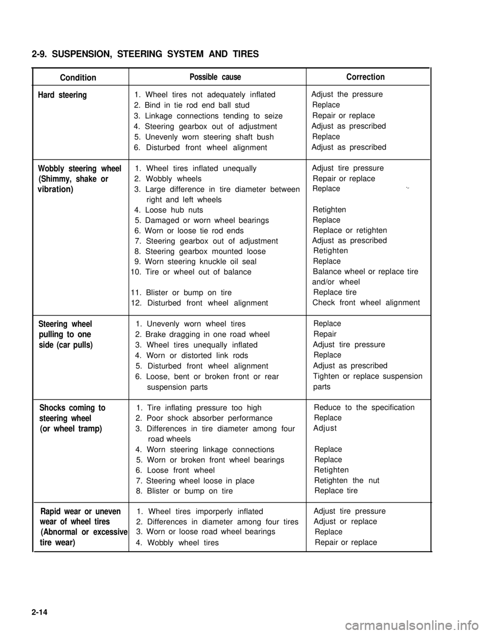
2-9. SUSPENSION, STEERING SYSTEM AND TIRES
Condition
Hard steering
Possible causeCorrection
1. Wheel tires not adequately inflatedAdjust the pressure
2. Bind in tie rod end ball studReplace
3. Linkage connections tending to seizeRepair or replace
4. Steering gearbox out of adjustmentAdjust as prescribed
5. Unevenly worn steering shaft bushReplace
6. Disturbed front wheel alignmentAdjust as prescribed
Wobbly steering wheel1. Wheel tires inflated unequallyAdjust tire pressure
(Shimmy, shake or2. Wobbly wheelsRepair or replace
vibration)3. Large difference in tire diameter betweenReplace._
right and left wheels
4. Loose hub nutsRetighten
5. Damaged or worn wheel bearingsReplace
6. Worn or loose tie rod endsReplace or retighten
7. Steering gearbox out of adjustmentAdjust as prescribed
8. Steering gearbox mounted looseRetighten
9. Worn steering knuckle oil sealReplace
10. Tire or wheel out of balanceBalance wheel or replace tire
and/or wheel
11. Blister or bump on tireReplace tire
12. Disturbed front wheel alignmentCheck front wheel alignment
Steering wheel
pulling to one
side (car pulls)
1. Unevenly worn wheel tires
2. Brake dragging in one road wheel
3. Wheel tires unequally inflated
4. Worn or distorted link rods
5. Disturbed front wheel alignment
6. Loose, bent or broken front or rear
suspension parts
Replace
Repair
Adjust tire pressure
Replace
Adjust as prescribed
Tighten or replace suspension
parts
Shocks coming to1. Tire inflating pressure too highReduce to the specification
steering wheel2. Poor shock absorber performanceReplace
(or wheel tramp)3. Differences in tire diameter among fourAdjust
road wheels
4. Worn steering linkage connectionsReplace
5. Worn or broken front wheel bearingsReplace
6. Loose front wheelRetighten
7. Steering wheel loose in placeRetighten the nut
8. Blister or bump on tireReplace tire
Rapid wear or uneven1. Wheel tires imporperly inflatedAdjust tire pressure
wear of wheel tires2. Differences in diameter among four tiresAdjust or replace
(Abnormal or excessive3. Worn or loose road wheel bearingsReplace
tire wear)4. Wobbly wheel tiresRepair or replace
2-14
Page 53 of 962
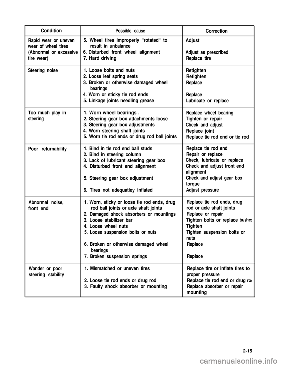
ConditionPossible causeCorrection
Rapid wear or uneven5. Wheel tires improperly “rotated“ toAdjust
wear of wheel tiresresult in unbalance
(Abnormal or excessive6. Disturbed front wheel alignmentAdjust as prescribed
tire wear)7. Hard drivingReplace tire
Steering noise1. Loose bolts and nuts
2. Loose leaf spring seats
3. Broken or otherwise damaged wheel
bearings
4. Worn or sticky tie rod ends
5. Linkage joints needling grease
Retighten
Retighten
Replace
Replace
Lubricate or replace
Too much play in
steering
1. Worn wheel bearings .Replace wheel bearing
2. Steering gear box attachments looseTighten or repair
3. Steering gear box adjustmentsCheck and adjust
4. Worn steering shaft jointsReplace joint
5. Worn tie rod ends or drug rod ball jointsReplace tie rod end or tie rod
Poor returnability1. Bind in tie rod end ball studs
2. Bind in steering column
3. Lack of lubricant steering gear box
4. Disturbed front end alignment
5. Steering gear box adjustment
6. Tires not adequatley inflated
Replace tie rod end
Repair or replace
Check, lubricate or replace
Check and adjust front end
alignment
Check and adjust gear box
torque
Adjust pressure
Abnormal noise,
front end
1. Worn, sticky or loose tie rod ends, drug
rod ball joints or axle shaft joints
2. Damaged shock absorbers or mountings
3. Loose stabilizer bar
4. Loose wheel nuts
5. Loose suspension bolts or nuts
6. Broken or otherwise damaged wheel
bearings
7. Broken suspension springs
Replace tie rod ends, drug
rod or axle shaft joints
Replace or repair
Tighten bolts or replace bushe!
Tighten
Tighten suspension bolts or
nuts
Replace
Replace
Wander or poor
steering stability
1. Mismatched or uneven tires
2. Loose tie rod ends or drug rod
3. Faulty shock absorber or mounting
Replace tire or inflate tires to
proper pressure
Replace tie rod end or drug ro(
Replace absorber or repair
mounting
2-15
Page 312 of 962
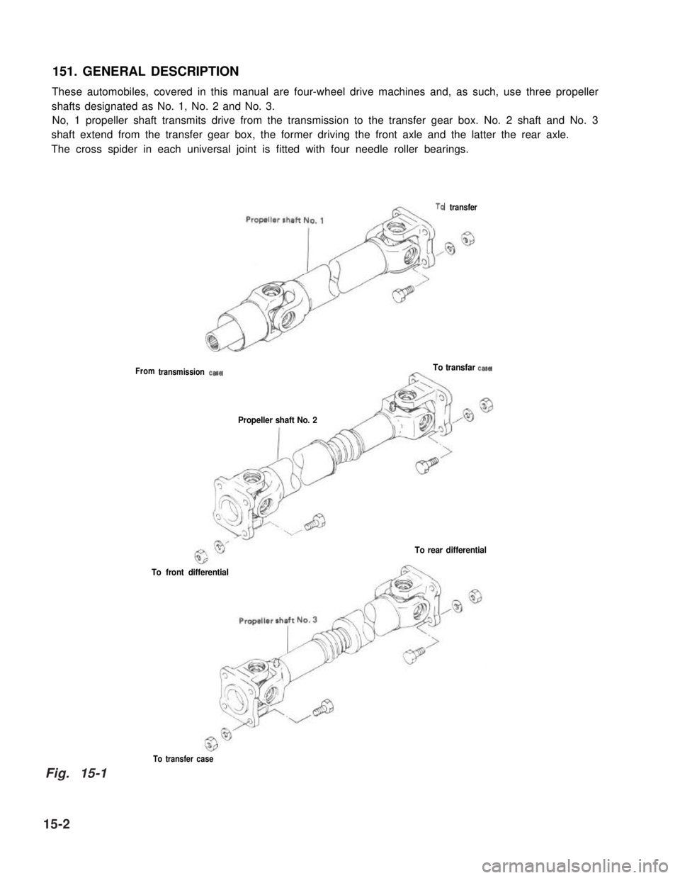
151. GENERAL DESCRIPTION
These automobiles, covered in this manual are four-wheel drive machines and, as such, use three propeller
shafts designated as No. 1, No. 2 and No. 3.
No, 1 propeller shaft transmits drive from the transmission to the transfer gear box. No. 2 shaft and No. 3
shaft extend from the transfer gear box, the former driving the front axle and the latter the rear axle.
The cross spider in each universal joint is fitted with four needle roller bearings.
From
TQ transfer
transmission casaTo transfar casa
Propeller shaft No. 2
To rear differential
To front differential
To transfer case
15-2
Fig. 15-1
Page 333 of 962
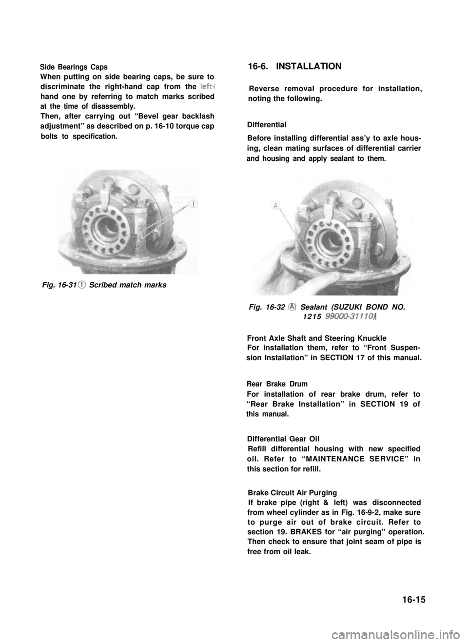
Side Bearings Caps
When putting on side bearing caps, be sure to
discriminate the right-hand cap from the left-
hand one by referring to match marks scribed
at the time of disassembly.
Then, after carrying out “Bevel gear backlash
adjustment” as described on p. 16-10 torque cap
bolts to specification.
16-6. INSTALLATION
Reverse removal procedure for installation,
noting the following.
Differential
Before installing differential ass’y to axle hous-
ing, clean mating surfaces of differential carrier
and housing and apply sealant to them.
Fig. 16-31 0 Scribed match marks
Fig. 16-32 @ Sealant (SUZUKI BOND NO.
1215 99000-31110)
Front Axle Shaft and Steering Knuckle
For installation them, refer to “Front Suspen-
sion Installation” in SECTION 17 of this manual.
Rear Brake Drum
For installation of rear brake drum, refer to
“Rear Brake Installation” in SECTION 19 of
this manual.
Differential Gear Oil
Refill differential housing with new specified
oil. Refer to “MAINTENANCE SERVICE” in
this section for refill.
Brake Circuit Air Purging
If brake pipe (right & left) was disconnected
from wheel cylinder as in Fig. 16-9-2, make sure
to purge air out of brake circuit. Refer to
section 19. BRAKES for “air purging" operation.
Then check to ensure that joint seam of pipe is
free from oil leak.
16-15
Page 336 of 962
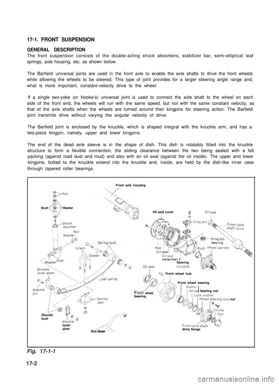
17-1. FRONT SUSPENSION
GENERAL DESCRIPTION
The front suspension consists of the double-acting shock absorbers, stabilizer bar, semi-elliptical leaf
springs, axle housing, etc. as shown below.
The Barfield universal joints are used in the front axle to enable the axle shafts to drive the front wheels
while allowing the wheels to be steered. This type of joint provides for a larger steering angle range and,
what is more important, constant-velocity drive to the wheel.
If a single two-yoke (or Hooke’s) universal joint is used to connect the axle shaft to the wheel on each
side of the front end, the wheels will run with the same speed, but not with the same constant velocity, as
that of the axle shafts when the wheels are turned around their kingpins for steering action. The Barfield
joint transmits drive without varying the angular velocity of drive.
The Barfield joint is enclosed by the knuckle, which is shaped integral with the knuckle arm, and has a
two-piece kingpin, namely, upper and lower kingpins.
The end of the dead axle sleeve is in the shape of dish. This dish is rotatably fitted into the knuckle
structure to form a flexible connection, the sliding clearance between the two being sealed with a felt
packing (against road dust and mud) and also with an oil seal (against the oil inside). The upper and lower
kingpins, bolted to the knuckle extend into the knuckle and, inside, are held by the dish-like inner case
through tapered roller bearings.
BushWasher
Front axle housing
Oil seal cover
retainer ISteeringLn,,rlrlo
Front wheel hub
Front wheel bearing
1\;lEkl bearing nutFront wheelbearina
Shacklebush
outerplateASta ilizer\drive flange
nut
Fig. 17-1-1
17-2