1987 SUZUKI GRAND VITARA odometer
[x] Cancel search: odometerPage 26 of 962
8. PCV VALVE REPLACEMENT
1) Disconnect crankcase ventilation hose from
PCV valve.
2) Remove PCV valve from intake manifold.
3) Wind sealing tape on thread of the new valve
and install it securely.
Tightenlng torque
for PCV valve
15-25 N.m
1.5-2.5 kg-m,
11 .O-18.0 lb-ft
4) Install hose and clamp it securely.
9. OXYGEN SENSOR REPLACEMENT
[Canadian specification vehicle]
When the odometer indicates 50,000 and 100,000
miles, replace oxygen sensor as follows.
CAUTION:
To avoid the danger of being burned, do
not touch the exhaust system when the
system is hot. This work should be perform-
ed when the system is cool.
1) Disconnect battery negative cable from
battery and disconnect oxygen sensor wire at
the coupler.
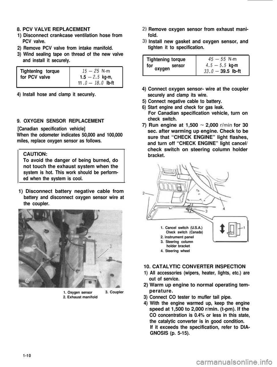
1. Oxygen sensor
2. Exhaust manifold
3. Coupler
2) Remove oxygen sensor from exhaust mani-
fold.
3) Install new gasket and oxygen sensor, and
tighten it to specification.
-Tightening45torque55 N-m
4.5-foroxygensensor5.5 kg-m
33.0-39.5 lb-ft
4) Connect oxygen sensor- wire at the coupler
securely and clamp its wire.
5) Connect negative cable to battery.
6) Start engine and check for gas leak.
For Canadian specification vehicle, turn on
check switch.
7) Run engine at 1,500 - 2,000 r/min for 30
sec. after warming up engine. Check to be
sure that “CHECK ENGINE” light flashes,
and turn off “CHECK ENGINE” light cancel/
check switch on steering column holder
bracket.
1. Cancel switch (U.S.A.)Check switch (Canada)
2. instrument panel
3. Steering columnholder bracket
4. Steering wheel
10. CATALYTIC CONVERTER INSPECTION
1) All accessories (wipers, heater, lights, etc.) are
out of service.
2) Warm up engine to normal operating tem-
perature.
3) Connect CO tester to mufler tail pipe.
4) With the engine warmed up, keep the engine
speed at 1,500 to 2,000 r/min. (t-pm). If the
CO concentration is 0.4% or less in this state,
the catalytic converter is in good condition.
If it exceeds the specification, refer to DIA-
GNOSIS (p. 5-15).
1-10
Page 173 of 962
[Jet1
1) Remove jet.
2) When blowing air into pipe 0, air should
come out of pipe 0.
Replace clogged jet.
3) Install jet with its gray side directed toward
MCV.
1. Pipe (Gray side)2.Pipe
33.Jet
Fig.53-134.Blowair
FEED BACK SYSTEM
Whether feed back system including oxygen sensor and ECM (Electronic Control Module) is in good
condition or not, can be judged by checking for operation of “CHECK ENGINE” light in instrument clus-
ter..
[U.S.A. specification vehicle]
As previously outlined,“CHECK ENGINE” light automatically flashes at 50,000 miles, 80,000 miles and
100,000 miles indicated on odometer when running warmed up engine. And this automatical flashing at
above mileages proves that system is in good condition.
Should any of following malcondition occur, the system check can be .performed according to “System
check flow chart”,even when mileage indicated by odometer is not any of 50,000 miles, 80,000 miles
and 100,000 miles.
[Canadian specification vehicle]
Should any of following malconditions occur, the system check can be performed according to “System
check flow chart”.
l Fuel consumption increases excssively even in normal driving.
l Engine tends to stall.
l Engine is hard to start.
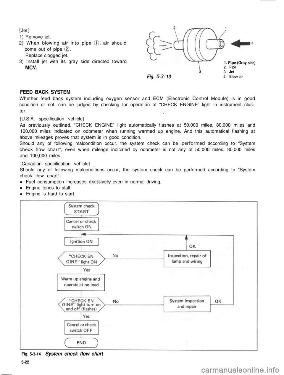
System check
STARTI
Cancel or check
switch ON
“CHECK EN-
Yes
Inspection, repair of
lamp and wiring1
Warm up engine and
operate at no load
I
“CHECK EN-GINE”light turnonand off (flashes)I
NoSystem inspection OK
and repair
Cancel or check
Fig. 5-3-14System check flow chart
5-22
Page 184 of 962
[Checking function of oxygen sensor and feed back system1
If oxygen sensor fails to send signal to the ECM, the feed back system does not operate. While the feed
back system is at work, the ECM sends out the feed back signal, and in this condition, after warming up
engine to normal operating temperature, when the cancel switch or check switch, is turned ON, the “CHECK
ENGINE” light in the instrument cluster flashes. If the “CHECK ENGINE” light does not flash in such
conditions as described above, check the feed back system for function according to the following pro-
cedure.
NOTE:
Except for Canadian specification vehicle, also when mileage sensor is turned ON (the odometer indicates
50,000, 80,000 or 100,000 miles), the “CHECK ENGINE” light flashes. If the “CHECK ENGINE” light
does not flash in such condition, check the feed back system for function according to the following
procedure.
1) Remove the ECM from the instrument main panel.
2) Connect the coupler to the ECM..
(Don’t disconnect the coupler from the ECM if connected)
3) Warm up the engine to the normal operating temperature and keep it at idle.
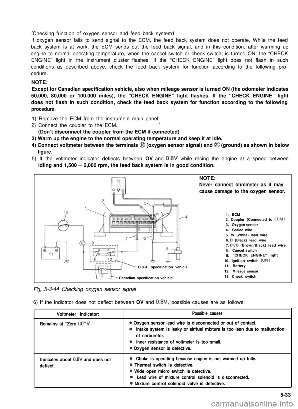
4) Connect voltmeter between the terminals @I (oxygen sensor signal) and @ (ground) as shown in below
figure.
5) If the voltmeter indicator deflects between OV and 0.8V while racing the engine at a speed between
idling and 1,500 - 2,000 rpm, the feed back system is in good condition.
Fig,
NOTE:
Never connect ohmmeter as it may
cause damage to the oxygen sensor.
U.S.A. specification vehicle
1.ECM2. Coupler (Connected to ECM)
3.Oxygen sensor
4.Sealed wire5. W (White) lead wire
6. I3 (Black) lead wire7. Br/B (Brown/Black) lead wire8.Cancel switch9.“CHECK ENGINE” light
10. Ignition switch (ON)11.Battery
12.Mileage sensor115 'L----JA Canadian specification vehicle
I 5-3-44 Checking oxygen sensor signal
13. Check switch
6) If the indicator does not deflect between OV and 0.8V, possible causes are as follows.
Voltmeter indicator:
Remains at “Zero (0)“V
Possible causes
0 Oxygen sensor lead wire is disconnected or out of contact.
0intake system is leaky or air/fuel mixture is too lean due to malfunction
of carburetor,
0Inner resistance of voltmeter is too small.
0 Oxygen sensor is defective.
Indicates about 0.8V and does not
deflect.
0Choke is operating because engine is not warmed up fully.
0 Thermal switch is defective.
0 Wide open micro switch is defective.
0Lead wire of mixture control solenoid is disconnected.
0 Mixture control solenoid valve is defective.
5-33
Page 382 of 962
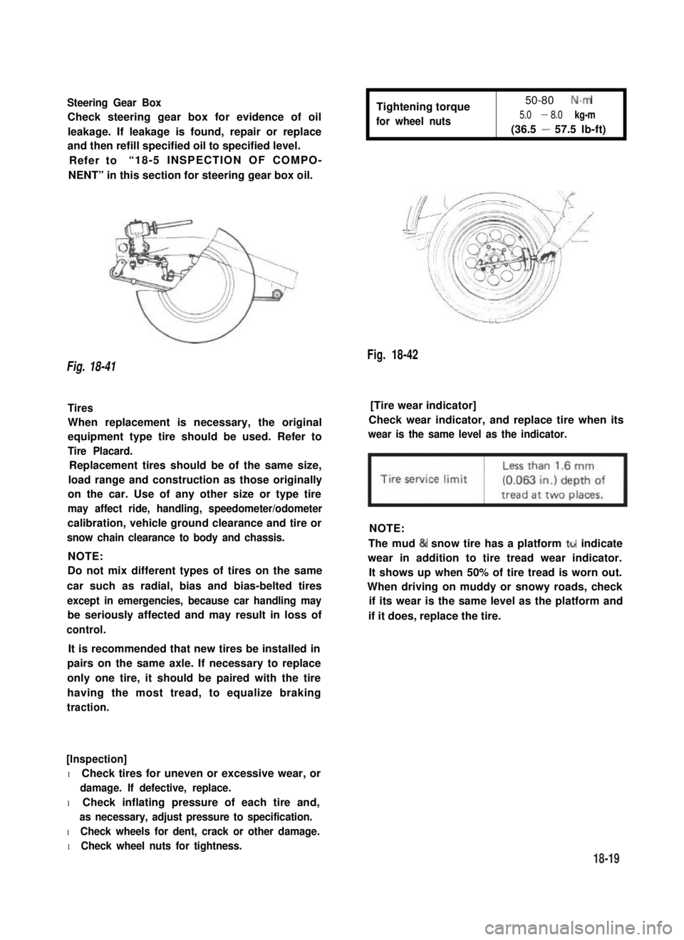
Steering Gear Box
Check steering gear box for evidence of oil
leakage. If leakage is found, repair or replace
and then refill specified oil to specified level.
Refer to“18-5 INSPECTION OF COMPO-
NENT” in this section for steering gear box oil.
Tightening torque
for wheel nuts
50-80 N.m
5.0 - 8.0 kg-m
(36.5 - 57.5 lb-ft)
Fig. 18-42
Fig. 18-41
Tires[Tire wear indicator]
When replacement is necessary, the original
equipment type tire should be used. Refer to
Tire Placard.
Check wear indicator, and replace tire when its
wear is the same level as the indicator.
Replacement tires should be of the same size,
load range and construction as those originally
on the car. Use of any other size or type tire
may affect ride, handling, speedometer/odometer
calibration, vehicle ground clearance and tire or
snow chain clearance to body and chassis.
NOTE:
NOTE:
Do not mix different types of tires on the same
car such as radial, bias and bias-belted tires
except in emergencies, because car handling may
be seriously affected and may result in loss of
control.
The mud & snow tire has a platform ttr indicate
wear in addition to tire tread wear indicator.
It shows up when 50% of tire tread is worn out.
When driving on muddy or snowy roads, check
if its wear is the same level as the platform and
if it does, replace the tire.
It is recommended that new tires be installed in
pairs on the same axle. If necessary to replace
only one tire, it should be paired with the tire
having the most tread, to equalize braking
traction.
[Inspection]
l Check tires for uneven or excessive wear, or
damage. If defective, replace.
l Check inflating pressure of each tire and,
as necessary, adjust pressure to specification.
l Check wheels for dent, crack or other damage.
l Check wheel nuts for tightness.
18-19
Page 383 of 962
![SUZUKI GRAND VITARA 1987 Service Repair Manual Fig. 18-43 @ Tire tread wear indicator
@ Wear indicating platform
[ Inflation of tires]
l Tire inflation pressures are listed on the
Tire Placard at driver’s side of instrument
panel.
l Tire inflati](/manual-img/20/57437/w960_57437-382.png "SUZUKI GRAND VITARA 1987 Service Repair Manual Fig. 18-43 @ Tire tread wear indicator
@ Wear indicating platform
[ Inflation of tires]
l Tire inflation pressures are listed on the
Tire Placard at driver’s side of instrument
panel.
l Tire inflati")
Fig. 18-43 @ Tire tread wear indicator
@ Wear indicating platform
[ Inflation of tires]
l Tire inflation pressures are listed on the
Tire Placard at driver’s side of instrument
panel.
l Tire inflation pressures should be checked
(including spare tire) at least monthly and
when significantly changing the load in the
car.
l Always check tire inflation pressures when
tires are “cold”.
l Always use tire pressure gauge when checking
inflation pressure.
l Be sure to reinstall tire inflation valve caps to
prevent dirt and moisture from getting into
valve core, as they may cause air leakage.
l If air loss occurs while driving, do not drive
on the deflated tire more than is needed to
stop safety. Driving even a short distance on a
deflated tire can damage a tire and wheel
beyond repair.
NOTE:
Before installing wheels, remove any build-up of
corrosion on the wheel mounting surface and
brake drum or disc mounting surface by scraping
and wire brushing. Installing wheels without
good metal-to-metal contact at the mounting
surfaces can cause wheel nuts to loosen, which
can later allow a wheel to come off while the
car is moving.
RADIAL TIRES
.i II
9T
\
I
4-wheels
Fig. 18-44
fT
u
[I
5-wheels
[Wheels]
Wheels must be replaced if they are bent, dented,
have excessive lateral or radial runout, leak air
through welds, have elongated bolt holes, if
lug nuts won’t stay tight, or if they are heavily
rusted. Wheels with greater runout than shown
in below figure may cause objectional vibrations.
Replacement wheels must be equivalent to the
original equipment wheels in load capacity,
diameter,rim width, offset and mounting
configuration. A wheel of improper size or type
may affect wheel and bearing life, brake cooling,
speedometer/odometer calibration, car ground
clearance and tire clearance to the body and
chassis.
[Tire rotation]
“Rotate” tires at the regular intervals in order to
equalize tire wear and thereby make full use of
each tire. Refer to below figure for the scheme
of rotation. Adherence to this scheme prolongs
tire life.
18-20