1987 SUZUKI GRAND VITARA change time
[x] Cancel search: change timePage 1 of 962

FOREWORD
This manual contains procedures for diagnosis, maintenance adjustments, \
service operations,
replacement of components (Service) and for disassembly and assembly o\
f major compo-
nents.
The contents are classified into sections each of which is given a secti\
on number as indicated
in the Table of Contents on next page. And on the first page of each ind\
ividual section is an
index of that section.
This manual should be kept in a handy place for ready reference of the s\
ervice work. Strict
observance of the so specified items will enable one to obtain the full \
performance of the
vehicle.
When replacing parts or servicing by disassembling, it is recommended to\
use SUZUKI
genuine parts, tools and service materials (lubricants, sealants, etc.)\
as specified in each
description.
All information, illustrations and specifications contained in this lite\
rature are based on the
latest product information available at the time of publication approval\
. The right is reserved
to make changes at any time without notice. And used as the main subject\
of description is
the vehicle of standard specifications among others. Therefore, note tha\
t illustrations and
photos may differ from the vehicle being actually serviced.
IMPORTANT:
It is important to note that, during any vehicle maintenance procedures,\
replacement
fasteners must have the same measurements as those removed.
Mismatched or incorrect fasteners can result in vehicle damage or malfun\
ction, or possible
personal injury.
Therefore, fasteners removed from the vehicle should be saved for re-use\
whenever possible.
Where the fasteners are not satisfactory for reuse, care should be taken\
to select a replace-
ment that matches the original.
Additional information concerning this subject will be found in the sect\
ion 0 (METRIC
INFORMATION).
This service manual is applicable to vehicles of and after the following\
body number.
Effective body No.:
J4235001
SUZUKI MOTOR
TECHNICAL DEPARTMENT
AUTOMOBILE SERVICE DIVISION
0 COPYRIGHT SUZUKI MOTOR CO., LTD. 1987
CO LTD
JS3JC51C J4235001
JS3JC51V J4150001
JS4JC51C J4235001
JS4JC51V 54150001
Page 5 of 962
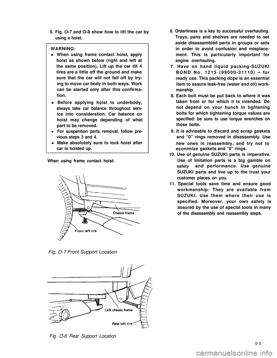
5. Fig. O-7 and O-8 show how to lift the car by
using a hoist.
WARNING:
l When using frame contact hoist, apply
hoist as shown below (right and left at
the same position), Lift up the car till 4
tires are a little off the ground and make
sure that the car will not fall off by try-
ing to move car body in both ways. Work
can be started only after this confirma-
tion.
l Before applying hoist to underbody,
always take car balance throughout serv-
ice into consideration. Car balance on
hoist may change depending of what
part to be removed.
lFor suspention parts removal, follow pre-
vious steps 3 and 4.
l Make absolutely sure to lock hoist after
car is hoisted up.
When using frame contact hoist:
6. Orderliness is a key to successful overhauling.
Trays, pans and shelves are needed to set
aside disassembled parts in groups or sets
in order to avoid confusion and misplace-
ment. This is particularly important for
engine overhauling.
7. Have on hand liquid packing-SUZUKI
BOND No. 1215 (99000-31110) - for
ready use. This packing dope is an essential
item to assure leak-free (water and oil) work-
manship.
8. Each bolt must be put back to where it was
taken from or for which it is intended. Do
not depend on your hunch in tightening
bolts for which tightening torque values are
specified: be sure to use torque wrenches on
those bolts.
9. It is advisable to discard and scrap gaskets
and “0” rings removed in disassembly. Use
new ones in reassembly, and try not to
econimize gaskets and “0” rings.
10. Use of genuine SUZUKI parts is imperative.
Use of imitation parts is a big gamble on
safetyand performance. Use genuine
SUZUKI parts and live up to the trust your
customer places on you.
11. Special tools save time and ensure good
workmanship: They are available from
SUZUKI. Use them where their use is
specified. Moreover, your own safety is
assured by the use of special tools in many
of the disassembly and reassembly steps.
Fig. O-7 Front Support Location
Fig. O-8 Rear Support Location
0-3
Page 33 of 962
1-3. CHASSIS AND BODY
30. CLUTCH PEDAL INSPECTION
1) Check clutch pedal height. It should be the
same as brake pedal height.
2) Check clutch pedal free travel.
Clutch pedal free travel20 - 30 mm
(0.8 - 1.1 in.)
For the details of the above steps 1) and 2),
refer to MAINTENANCE SERVICE (p. 11-8) of
SECTION 11.
31. BRAKE DISCS, PADS, BRAKE DRUMS
AND SHOES INSPECTION
Brake Discs and Pads
I) Remove wheel and caliper but don’t discon-
nect brake hose from caliper.
2) Check front disc brake pads and discs for
excessivewear,damageand deflection.
Replace parts as necessary. For the details,
refer to p. 19-I 6 and 19-I 7 of SECT ION 19.
Be sure to torque caliper guide pins to specifi-
cation for reinstallation.
Brake Drums and Shoes
I) Remove wheel and brake drum.
2) Check rear brake drums and brake linings for
excessive wear and damage, while wheels and
drums are removed. Also check wheel cylin-
ders for leaks, at the same time. Replace
these parts as necessary.
For the details, refer to p. 19-21 and p. 19-
22 of SECTION 19.
32. BRAKE HOSES AND PIPES INSPECTION
Check brake hoses and pipes for proper hook-
up, leaks, cracks, chafing and other damage.
Replace any of these parts as necessary.
CAUTION:
After replacing any brake pipe or hose, be
sure to carry out air purge operation.
33. BRAKE FLUID INSPECTION AND
CHANGE
[INSPECTION]
1) Check around master cylinder and reservoir
for fluid leakage.
If found leaky, correct.
2) Check fluid level
If fluid level is lower than the minimum level
of reservoir, refilling is necessary. Fill reservoir
with specified brake fluids.
Brake fluid Speifi;t3ons
For the details, refer to MAINTENANCE
SERVICE (p. 19-42) of SECTION 19.
CAUTION:
Since the brake system of this car is factory-
filled with glycol-base brake fluid, do not
use or mix different type of fluid when
refilling the system; otherwise serious
damage will occur. Do not use old or used
brake fluid, or one taken from unsealed
container.
[CHANGE]
1) Change brake fluid. As fluid change procedure,
drain existing fluid from brake system com-
pletely, fill the system with above recom-
mended fluid and carry out air purge opera-
tion.
For description of air purge, refer to p. 19-46
and 19-47 of SECTION 19.
34. BRAKE PEDAL INSPECTION
Check brake pedal travel.
For -checking procedure, refer to PEDAL TRA-
VEL CHECK (p. 19-43) of SECTION 19.
35. BRAKE LEVER AND CABLE
INSPECTION
Parking Brake Lever
I) Check tooth tip of each notch for damage or
wear. If any damage or wear is found, replace
parking lever.
2) Check parking brake lever for proper opera-
tion and stroke, and adjust it if necessary.
For checking and adjusting procedures,
refer to PARKING BRAKE INSPECTION
AND ADJUSTMENT (p. 19-44) of SECTION
19.
1-17
Page 61 of 962
3) Cylinder Head and Valve Train
The cylinder head is made of cast aluminum alloy and has four combustion chambers arranged in-line.
Each combustion chamber has an intake and an exhaust ports.
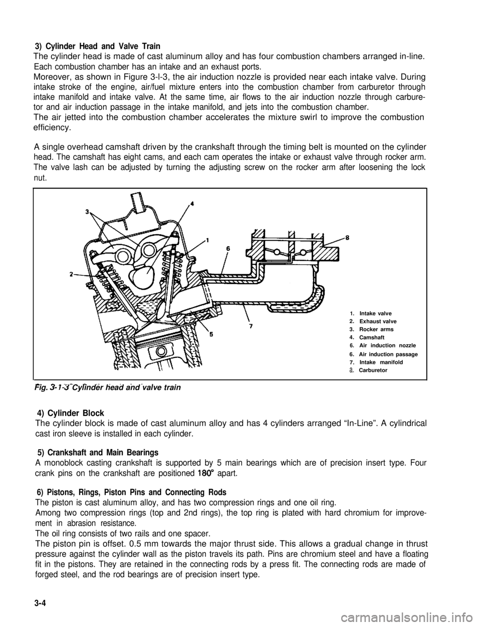
Moreover, as shown in Figure 3-l-3, the air induction nozzle is provided near each intake valve. During
intake stroke of the engine, air/fuel mixture enters into the combustion chamber from carburetor through
intake manifold and intake valve. At the same time, air flows to the air induction nozzle through carbure-
tor and air induction passage in the intake manifold, and jets into the combustion chamber.
The air jetted into the combustion chamber accelerates the mixture swirl to improve the combustion
efficiency.
A single overhead camshaft driven by the crankshaft through the timing belt is mounted on the cylinder
head. The camshaft has eight cams, and each cam operates the intake or exhaust valve through rocker arm.
The valve lash can be adjusted by turning the adjusting screw on the rocker arm after loosening the lock
nut.
2-
1.Intake valve2.Exhaust valve
3.Rocker arms
4.Camshaft
6.Air induction nozzle
6.Air induction passage
7.Intake manifold
a.Carburetor
-. - _- - ._ . . . . .Fig. 3- 7-3 Cylinder head and valve train
4) Cylinder Block
The cylinder block is made of cast aluminum alloy and has 4 cylinders arranged “In-Line”. A cylindrical
cast iron sleeve is installed in each cylinder.
5) Crankshaft and Main Bearings
A monoblock casting crankshaft is supported by 5 main bearings which are of precision insert type. Four
crank pins on the crankshaft are positioned 180” apart.
6) Pistons, Rings, Piston Pins and Connecting Rods
The piston is cast aluminum alloy, and has two compression rings and one oil ring.
Among two compression rings (top and 2nd rings), the top ring is plated with hard chromium for improve-
ment in abrasion resistance.
The oil ring consists of two rails and one spacer.
The piston pin is offset. 0.5 mm towards the major thrust side. This allows a gradual change in thrust
pressure against the cylinder wall as the piston travels its path. Pins are chromium steel and have a floating
fit in the pistons. They are retained in the connecting rods by a press fit. The connecting rods are made of
forged steel, and the rod bearings are of precision insert type.
3-4
Page 142 of 962
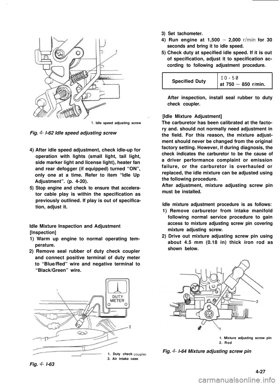
1. Idle speed adjusting screw
Fig. 4- l-62 Idle speed adjusting screw
4) After idle speed adjustment, check idle-up for
operation with lights (small light, tail light,
side marker light and license light), heater fan
and rear defogger (if equipped) turned “ON”,
only one at a time. Refer to item “Idle Up
Adjustment”. (p. 4-20).
5) Stop engine and check to ensure that accelera-
tor cable play is within the specification as
previously outlined. If play is out of specifica-
tion, adjust it.
Idle Mixture Inspection and Adjustment
[Inspection]
1) Warm up engine to normal operating tem-
perature.
2) Remove seal rubber of duty check coupler
and connect positive terminal of duty meter
to “Blue/Red” wire and negative terminal to
“Black/Green” wire.
1
1. Duty check
3) Set tachometer.
4) Run engine at 1,500 - 2,000 r/min for 30
seconds and bring it to idle speed.
5) Check duty at specified idle speed. If it is out
of specification, adjust it to specification ac-
cording to following adjustment procedure.
Specified DutyIO-50
at 750 - 850 r/min.
After inspection, install seal rubber to duty
check coupler.
[Idle Mixture Adjustment]
The carburetor has been calibrated at the facto-
ry and. should not normally need adjustment in
the field. For this reason, the mixture adjust-
ment should never be changed from the original
factory setting. However, if during diagnosis, the
check indicates the carburetor to be the cause of
a driver performance complaint or emission
failure, or the carburetor is overhauled or
replaced, the idle mixture can be adjusted using
the following procedure.
After adjustment, mixture adjusting screw pin
must be installed.
Idle mixture adjustment procedure is as follows:
1) Remove carburetor from intake manifold
following normal service procedure to gain
access to mixture adjusting screw pin covering
mixture adjusting screw.
2) Drive out mixture adjusting screw pin using
about 4.5 mm (0.18 in) thick iron rod as
shown below.
1. Mixture adjusting screw pin2. Rod
Fig. 4- l-64 Mixture adjusting screw pin
2. Air intake case
Fig. 4- l-63
4-27
Page 212 of 962
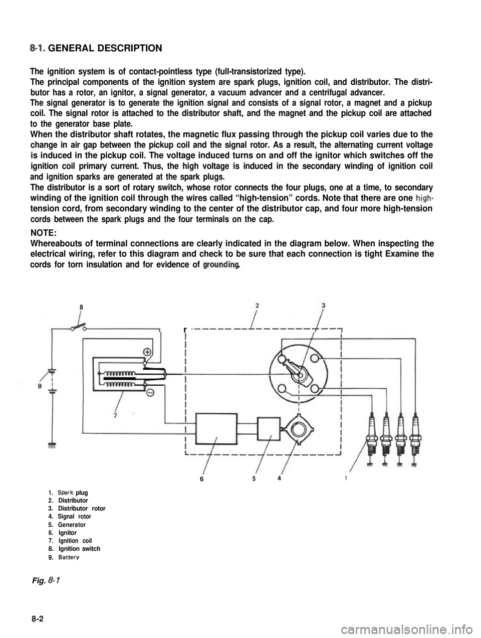
8-l. GENERAL DESCRIPTION
The ignition system is of contact-pointless type (full-transistorized type).
The principal components of the ignition system are spark plugs, ignition coil, and distributor. The distri-
butor has a rotor, an ignitor, a signal generator, a vacuum advancer and a centrifugal advancer.
The signal generator is to generate the ignition signal and consists of a signal rotor, a magnet and a pickup
coil. The signal rotor is attached to the distributor shaft, and the magnet and the pickup coil are attached
to the generator base plate.
When the distributor shaft rotates, the magnetic flux passing through the pickup coil varies due to the
change in air gap between the pickup coil and the signal rotor. As a result, the alternating current voltage
is induced in the pickup coil. The voltage induced turns on and off the ignitor which switches off the
ignition coil primary current. Thus, the high voltage is induced in the secondary winding of ignition coil
and ignition sparks are generated at the spark plugs.
The distributor is a sort of rotary switch, whose rotor connects the four plugs, one at a time, to secondary
winding of the ignition coil through the wires called “high-tension” cords. Note that there are one high-
tension cord, from secondary winding to the center of the distributor cap, and four more high-tension
cords between the spark plugs and the four terminals on the cap.
NOTE:
Whereabouts of terminal connections are clearly indicated in the diagram below. When inspecting the
electrical wiring, refer to this diagram and check to be sure that each connection is tight Examine the
cords for torn insulation and for evidence of groundinq
8
r
6541
1.Spark plug2.Distributor3.Distributor rotor4.Signal rotor
5.Generator6.lgnitor7.Ignition coil8.Ignition switch
9.Battery
Fig. 8- 1
8-2
Page 328 of 962
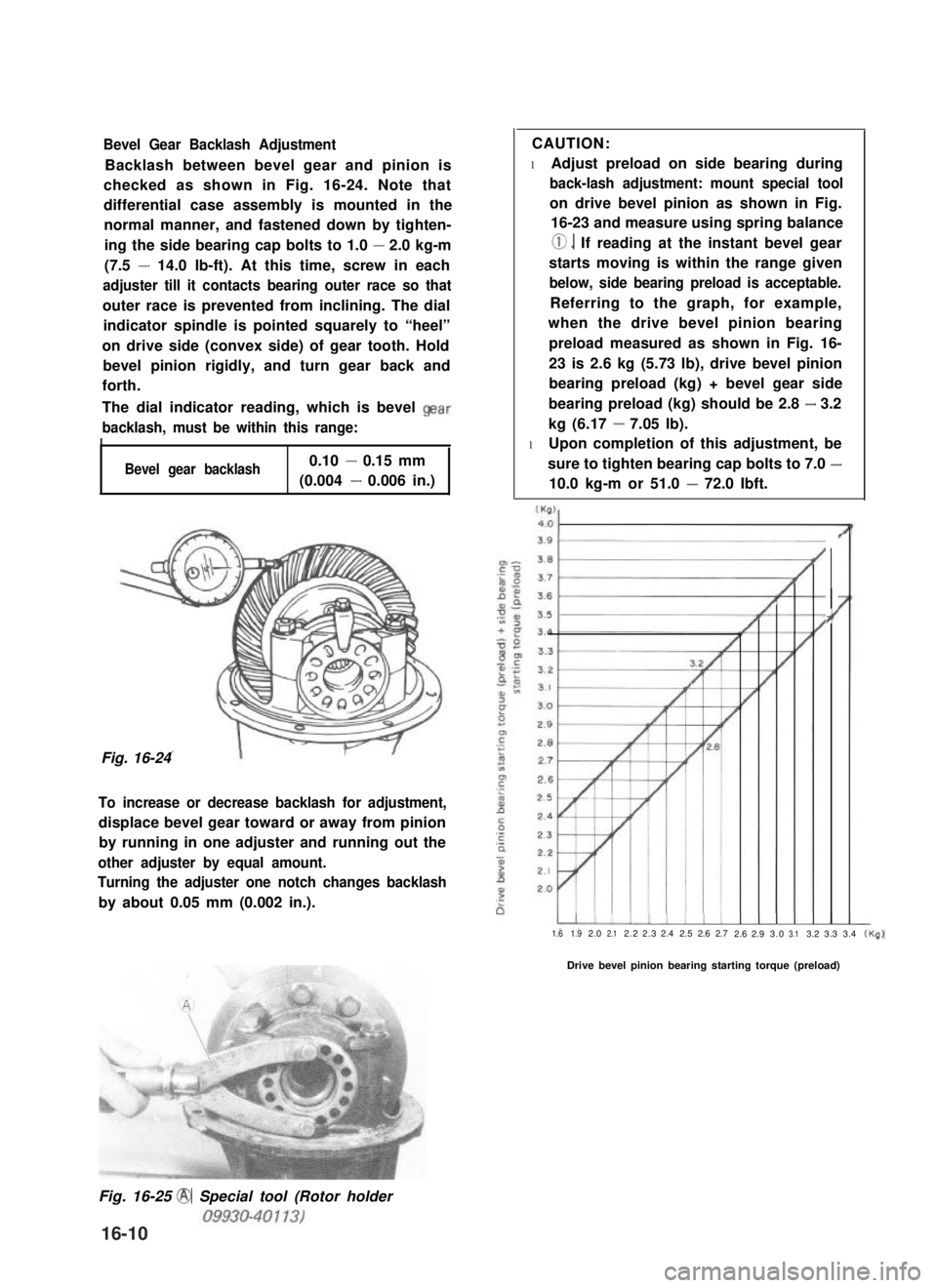
Bevel Gear Backlash Adjustment
Backlash between bevel gear and pinion is
checked as shown in Fig. 16-24. Note that
differential case assembly is mounted in the
normal manner, and fastened down by tighten-
ing the side bearing cap bolts to 1.0 - 2.0 kg-m
(7.5 - 14.0 lb-ft). At this time, screw in each
adjuster till it contacts bearing outer race so that
outer race is prevented from inclining. The dial
indicator spindle is pointed squarely to “heel”
on drive side (convex side) of gear tooth. Hold
bevel pinion rigidly, and turn gear back and
forth.
The dial indicator reading, which is bevel Qear
backlash, must be within this range:
I
Bevel gear backlash0.10 - 0.15 mm
(0.004 - 0.006 in.)
Fig. 16-24
To increase or decrease backlash for adjustment,
displace bevel gear toward or away from pinion
by running in one adjuster and running out the
other adjuster by equal amount.
Turning the adjuster one notch changes backlash
by about 0.05 mm (0.002 in.).
CAUTION:
l Adjust preload on side bearing during
back-lash adjustment: mount special tool
on drive bevel pinion as shown in Fig.
16-23 and measure using spring balance
0. If reading at the instant bevel gear
starts moving is within the range given
below, side bearing preload is acceptable.
Referring to the graph, for example,
when the drive bevel pinion bearing
preload measured as shown in Fig. 16-
23 is 2.6 kg (5.73 lb), drive bevel pinion
bearing preload (kg) + bevel gear side
bearing preload (kg) should be 2.8 - 3.2
kg (6.17 - 7.05 lb).
l Upon completion of this adjustment, be
sure to tighten bearing cap bolts to 7.0 -
10.0 kg-m or 51.0 - 72.0 Ibft.
?’
1.61.92.02.12.22.32.42.52.62.72.62.93.03.13.23.33.4(Kg)
Drive bevel pinion bearing starting torque (preload)
Fig. 16-25 @ Special tool (Rotor holder
16-10
Page 392 of 962
![SUZUKI GRAND VITARA 1987 Service Repair Manual [Caliper OPERATION]
Single piston floating caliper type
The single piston floating caliper type brake is
employed in this model. One cylinder and one
piston are used for this type. (The cylinder is
co SUZUKI GRAND VITARA 1987 Service Repair Manual [Caliper OPERATION]
Single piston floating caliper type
The single piston floating caliper type brake is
employed in this model. One cylinder and one
piston are used for this type. (The cylinder is
co](/manual-img/20/57437/w960_57437-391.png)
[Caliper OPERATION]
Single piston floating caliper type
The single piston floating caliper type brake is
employed in this model. One cylinder and one
piston are used for this type. (The cylinder is
constructed as a monoblock with the caliper.)
Fluid pressure generated in the cylinder causes
the pad (1) on the piston side to press against
the disc. At the same time, the floating type
caliper body is moved to the right by the cylin-
der pressure, as shown in below figure, which
pulls pad (2) against the disc and so brakes the
wheel.
Caliper body
\Brake disc (rotor)
Fig. 19-6 - ’
The disc brake has no servo assistance as in drum
braking, and it is necessary to increase the work-
ing pressure of the piston and pad. For this pur-
pose, the wheel cylinder has a large bore. Even
only a little change in clearance between the disc
and pad has therefore a large influence on the
brake pedal stroke. It is necessary to have the
clearance adjusted to the minimum at all times,
by means of the piston (rubber) seal.
Piston seal (Rubber seal)Piston sealWinder (Rubber seal)
II
IPiston
Hydraulic pressure
“OFF“
Fig. 19-7
Clearance correction
Piston
Hydraulic pressure
“ON”
When oil pressure is applied to the piston, the
piston moves forward. The rubber seal, which
exerts considerable pressure against the piston,
moves with the cylinder. However, as a part of
the rubber seal has been fixed into a groove in
the cylinder, the shape of the rubber seal is dis-
torted toward internal end of the cylinder, as
shown in above figure. When pressure is taken
off from the foot brake pedal and fluid pressure
is released from the piston, a restoring force is
generated at the seal and pushes the piston back.
As the pads wear away and the clearance be-
tween the disc and pads becomes larger, the
piston moves a larger distance. The seal then
could change in shape further but, since the end
of the seal is fixed into the groove in the cylin-
der, the distortion is limited to the same amount
as previously described. The piston moves
further to cover the distance of clearance. The
piston returns by the same distance and the
rubber seal recovers its shape as described
above and thus the clearance between the disc
and pads are maintained in adjustment.
19-7
Cylinder