1987 SUZUKI GRAND VITARA oil type
[x] Cancel search: oil typePage 36 of 962
3) Check propeller shaft (No. 1, No. 2, No. 3)
flange yoke bolts for tightness, and retighten
them as necessary:
N.mkg-mlb-ftTighteningtorque23-302.3-3.017.0-21.5
42. TRANSMISSION, TRANSFER,
DIFFERENTIAL OIL INSPECTION
AND CHANGE
[I nspectionl
1) Inspect transmission case, transfer case and
differential housing for evidence of oil leakage.
Repair leaky point if any.
2) Make sure that the car is placed level for oil
level check.
3) Remove each level plug of transmission,
transfer and differential (front and rear).
In any of these cases, oil level can be checked
roughly by means of level plug hole. That is,
,if oil flows out of level plug hole or if oil
level is found up to hole when level plug is
removed, oil is properly filled.
If oil is found insufficient, pour specified
amount of specified oil as given in the below
table.
[Change]
Oil change procedure is as follows.
Place the car level and drain oil by removing
drain plug. Pour specified amount of specified
oil as in the below table and tighten drain plug
and filler plug to specified torque.
It is highly recommended to use SAE 75W-90
gear oil.
Viscosity chart
SAE
75w-ao,75w-90
"C -30 --20 -10 0 10 20 30 40"F -22 -4lb 32 50 68 86104
Temperature
Transmission oil change
Oil capacity
Type of oil
1.3 liters
(2.7/2.3 US/Imp pt.)
Gear oil, SAE
8OW-90,75W-80 or
75w-90
l-20
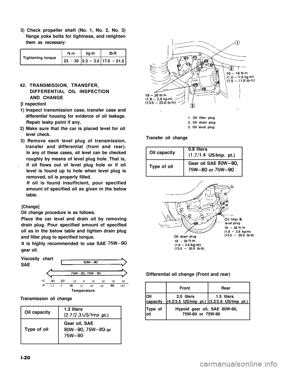
18-28N.m
I ”’
1. Oil filler plug
2. Oil drain plug
3. Oil level plug
Transfer oil change
Oil capacity0.8 liters
(1.7/l .4 US/Imp. pt.)
Type of oilGear oil SAE 8OW-90,
75W-80 or 75W-90
18 - 28 N.m(1.8 - 2.8 kg-m)(13.5 - 20.0 lb-ft)-R-Oil drair18 - 28 N&(1.8 - 2.8 kg-m)(13.5 - 20.0 lb-ft)
Differential oil change (Front and rear)
1.5 liters
(3.2/2.6 US/Imp pt.)
2.0 liters
(4.2/3.5 US/Imp pt.)
FrontRear
Oil
capacity
Type of
oil
Hypoid gear oil, SAE 80W-90,
75W-80 or 75W-90
Page 60 of 962
2) Engine Lubrication
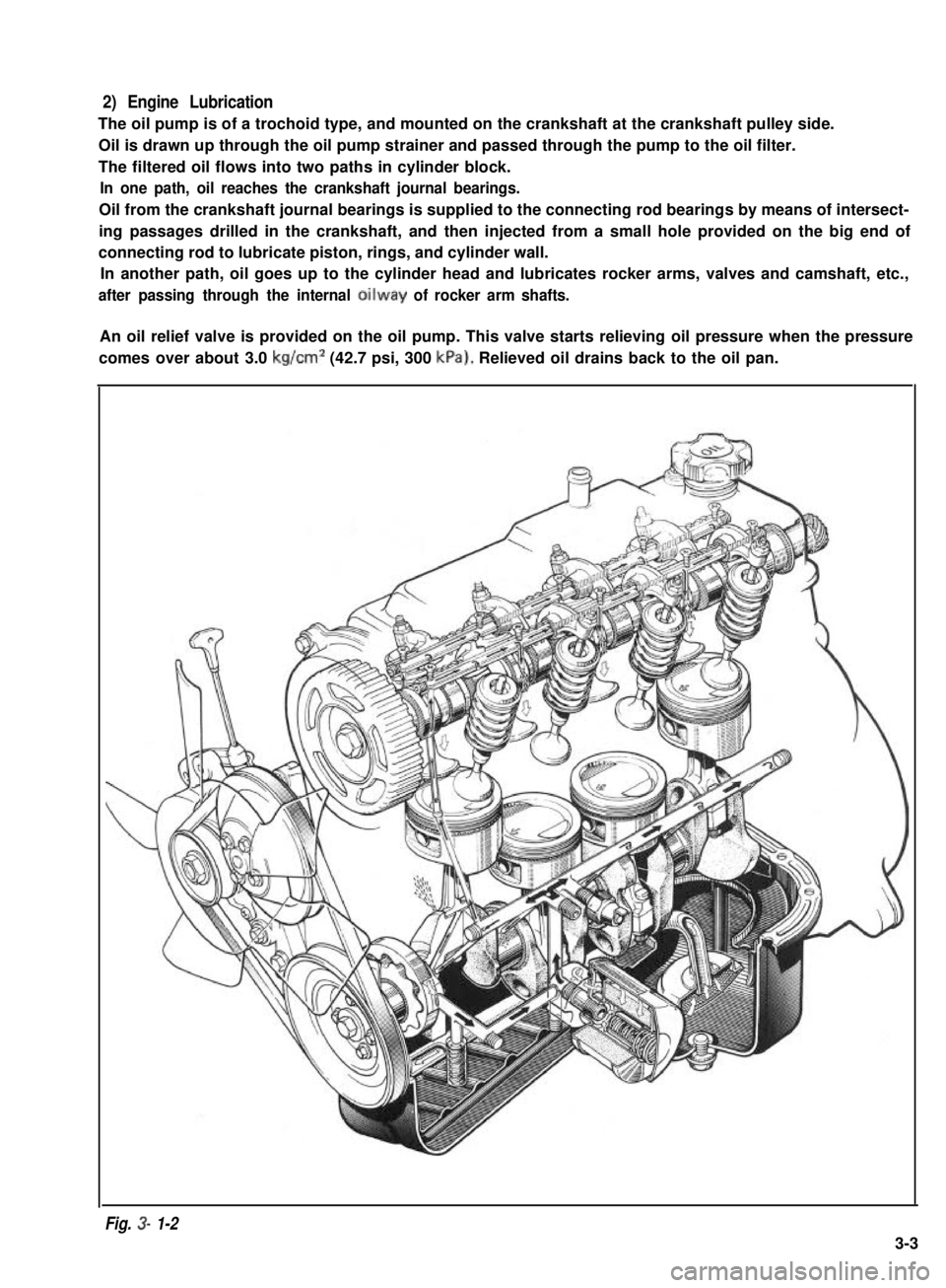
The oil pump is of a trochoid type, and mounted on the crankshaft at the crankshaft pulley side.
Oil is drawn up through the oil pump strainer and passed through the pump to the oil filter.
The filtered oil flows into two paths in cylinder block.
In one path, oil reaches the crankshaft journal bearings.
Oil from the crankshaft journal bearings is supplied to the connecting rod bearings by means of intersect-
ing passages drilled in the crankshaft, and then injected from a small hole provided on the big end of
connecting rod to lubricate piston, rings, and cylinder wall.
In another path, oil goes up to the cylinder head and lubricates rocker arms, valves and camshaft, etc.,
after passing through the internal oilway of rocker arm shafts.
An oil relief valve is provided on the oil pump. This valve starts relieving oil pressure when the pressure
comes over about 3.0 kg/cm2 (42.7 psi, 300 kPa). Relieved oil drains back to the oil pan.
Fig. 3- 1-2
3-3
Page 61 of 962
3) Cylinder Head and Valve Train
The cylinder head is made of cast aluminum alloy and has four combustion chambers arranged in-line.
Each combustion chamber has an intake and an exhaust ports.
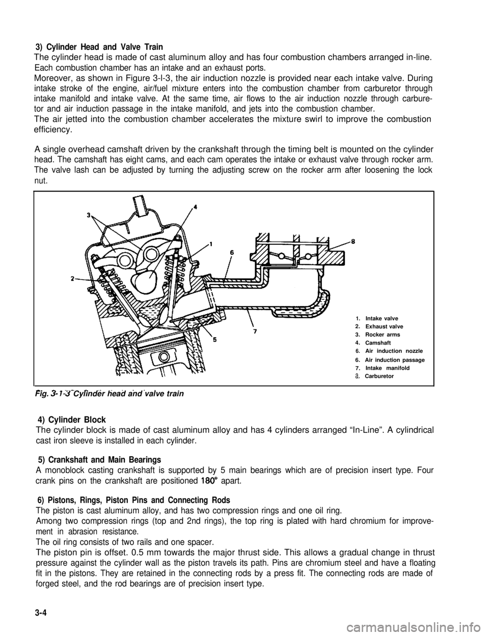
Moreover, as shown in Figure 3-l-3, the air induction nozzle is provided near each intake valve. During
intake stroke of the engine, air/fuel mixture enters into the combustion chamber from carburetor through
intake manifold and intake valve. At the same time, air flows to the air induction nozzle through carbure-
tor and air induction passage in the intake manifold, and jets into the combustion chamber.
The air jetted into the combustion chamber accelerates the mixture swirl to improve the combustion
efficiency.
A single overhead camshaft driven by the crankshaft through the timing belt is mounted on the cylinder
head. The camshaft has eight cams, and each cam operates the intake or exhaust valve through rocker arm.
The valve lash can be adjusted by turning the adjusting screw on the rocker arm after loosening the lock
nut.
2-
1.Intake valve2.Exhaust valve
3.Rocker arms
4.Camshaft
6.Air induction nozzle
6.Air induction passage
7.Intake manifold
a.Carburetor
-. - _- - ._ . . . . .Fig. 3- 7-3 Cylinder head and valve train
4) Cylinder Block
The cylinder block is made of cast aluminum alloy and has 4 cylinders arranged “In-Line”. A cylindrical
cast iron sleeve is installed in each cylinder.
5) Crankshaft and Main Bearings
A monoblock casting crankshaft is supported by 5 main bearings which are of precision insert type. Four
crank pins on the crankshaft are positioned 180” apart.
6) Pistons, Rings, Piston Pins and Connecting Rods
The piston is cast aluminum alloy, and has two compression rings and one oil ring.
Among two compression rings (top and 2nd rings), the top ring is plated with hard chromium for improve-
ment in abrasion resistance.
The oil ring consists of two rails and one spacer.
The piston pin is offset. 0.5 mm towards the major thrust side. This allows a gradual change in thrust
pressure against the cylinder wall as the piston travels its path. Pins are chromium steel and have a floating
fit in the pistons. They are retained in the connecting rods by a press fit. The connecting rods are made of
forged steel, and the rod bearings are of precision insert type.
3-4
Page 99 of 962
Oil Pump Strainer
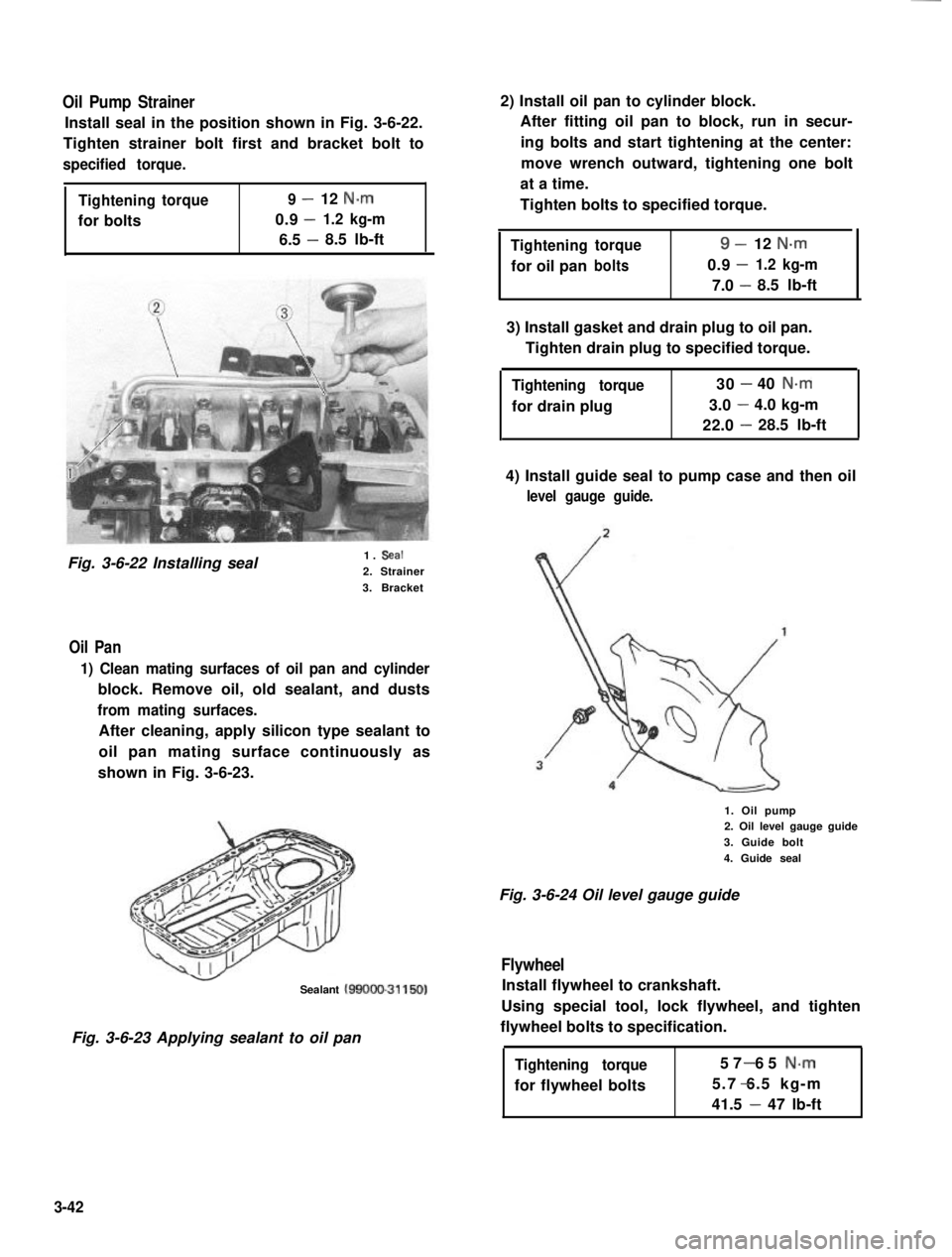
Install seal in the position shown in Fig. 3-6-22.
Tighten strainer bolt first and bracket bolt to
specified torque.
Tighteningtorque9-12 N.m
0.9-for bolts1.2 kg-m
6.5 -8.5 lb-ft
Fig. 3-6-22 Installing seal1. Seal
2. Strainer
3. Bracket
Oil Pan
1) Clean mating surfaces of oil pan and cylinder
block. Remove oil, old sealant, and dusts
from mating surfaces.
After cleaning, apply silicon type sealant to
oil pan mating surface continuously as
shown in Fig. 3-6-23.
Sealant MOOO-31150)
Fig. 3-6-23 Applying sealant to oil pan
2) Install oil pan to cylinder block.
After fitting oil pan to block, run in secur-
ing bolts and start tightening at the center:
move wrench outward, tightening one bolt
at a time.
Tighten bolts to specified torque.
Tighteningtorque9-12 N-m
-for oil panbolts0.91.2 kg-m
7.0 -8.5 lb-ft
3) Install gasket and drain plug to oil pan.
Tighten drain plug to specified torque.
Tightening torque
for drain plug
30-40 N.m
3.0-4.0 kg-m
22.0-28.5 lb-ft
4) Install guide seal to pump case and then oil
level gauge guide.
1. Oil pump2. Oil level gauge guide
3. Guide bolt
4. Guide seal
Fig. 3-6-24 Oil level gauge guide
Flywheel
Install flywheel to crankshaft.
Using special tool, lock flywheel, and tighten
flywheel bolts to specification.
Tightening torque
for flywheel bolts
57 65 N-m-
5.7 6.5 kg-m-
41.5 - 47 lb-ft
3-42
Page 212 of 962
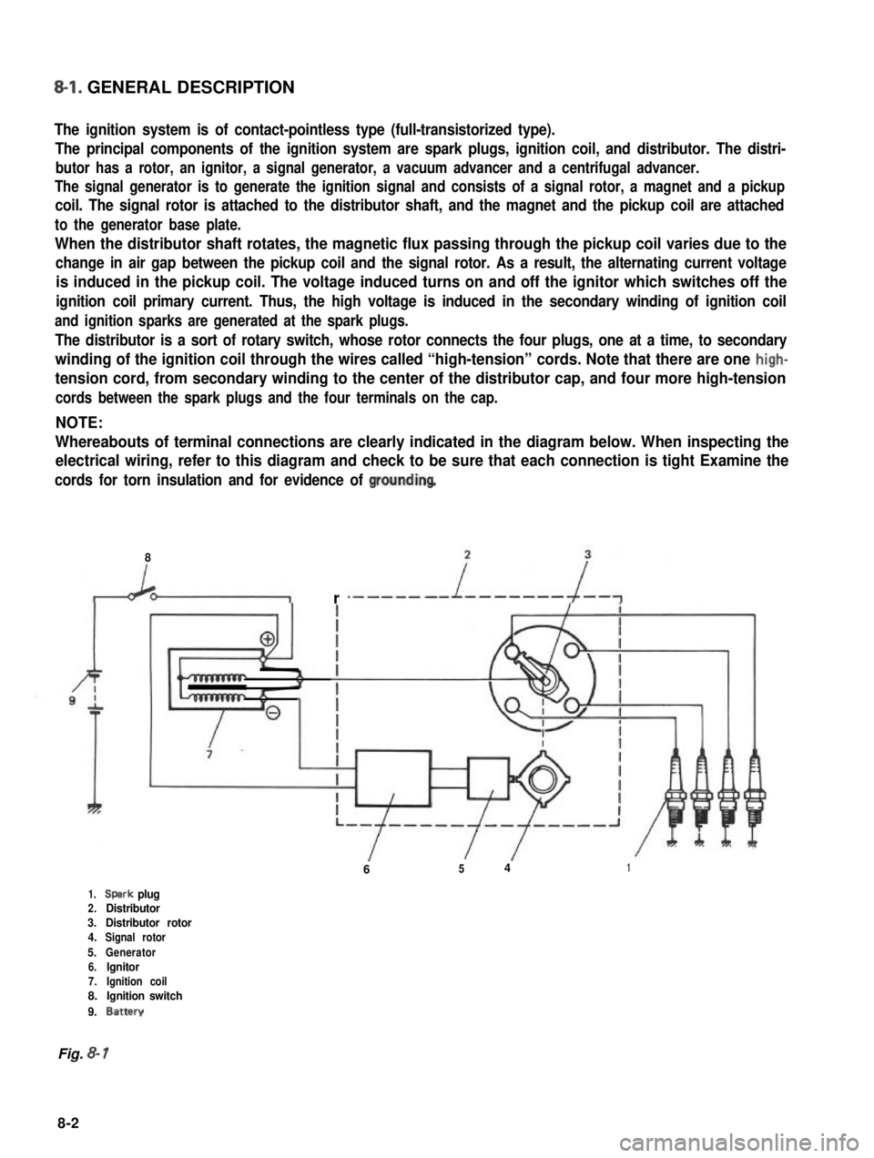
8-l. GENERAL DESCRIPTION
The ignition system is of contact-pointless type (full-transistorized type).
The principal components of the ignition system are spark plugs, ignition coil, and distributor. The distri-
butor has a rotor, an ignitor, a signal generator, a vacuum advancer and a centrifugal advancer.
The signal generator is to generate the ignition signal and consists of a signal rotor, a magnet and a pickup
coil. The signal rotor is attached to the distributor shaft, and the magnet and the pickup coil are attached
to the generator base plate.
When the distributor shaft rotates, the magnetic flux passing through the pickup coil varies due to the
change in air gap between the pickup coil and the signal rotor. As a result, the alternating current voltage
is induced in the pickup coil. The voltage induced turns on and off the ignitor which switches off the
ignition coil primary current. Thus, the high voltage is induced in the secondary winding of ignition coil
and ignition sparks are generated at the spark plugs.
The distributor is a sort of rotary switch, whose rotor connects the four plugs, one at a time, to secondary
winding of the ignition coil through the wires called “high-tension” cords. Note that there are one high-
tension cord, from secondary winding to the center of the distributor cap, and four more high-tension
cords between the spark plugs and the four terminals on the cap.
NOTE:
Whereabouts of terminal connections are clearly indicated in the diagram below. When inspecting the
electrical wiring, refer to this diagram and check to be sure that each connection is tight Examine the
cords for torn insulation and for evidence of groundinq
8
r
6541
1.Spark plug2.Distributor3.Distributor rotor4.Signal rotor
5.Generator6.lgnitor7.Ignition coil8.Ignition switch
9.Battery
Fig. 8- 1
8-2
Page 214 of 962
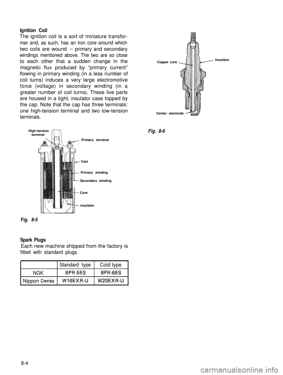
Ignition Coil
The ignition coil is a sort of miniature transfor-
mer and, as such, has an iron core around which
two coils are wound- primary and secondary
windings mentioned above. The two are so close
to each other that a sudden change in themagnetic flux produced by “primary current”
flowing in primary winding (in a less number of
coil turns) induces a very large electromotive force (voltage) in secondary winding (in a
greater number of coil turns). These live parts
are housed in a tight, insulator case topped by the cap. Note that the cap has three terminals:
one high-tension terminal and two low-tension
terminals.
High-tension terminal
Primary terminal
lt-
Case
It
Primary winding
II
Secondary winding
j- Core
m2 I,,,insulator
Fig. 8-5
Spark Plugs
Each new machine shipped from the factory is
fitted with standard plugs.
Copper core
Center electrode
Fig. 8-6 Insulator
Standard typeCold type
NGKBPRdESBPR-6ES
Nippon DensoWlGEXR-UW’LOEXR-U
8-4
Page 247 of 962
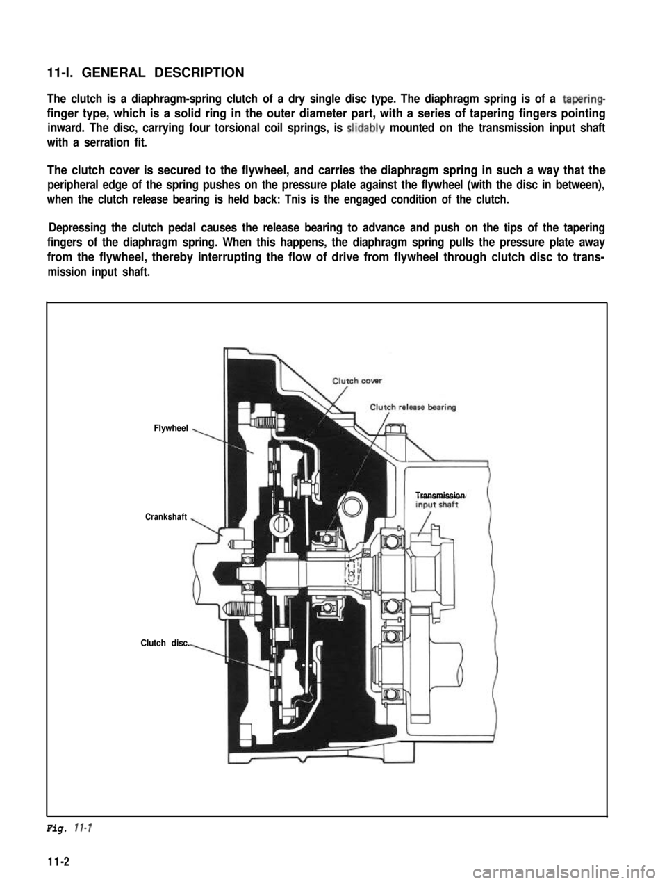
11-l. GENERAL DESCRIPTIONThe clutch is a diaphragm-spring clutch of a dry single disc type. The diaphragm spring is of a tapering-
finger type, which is a solid ring in the outer diameter part, with a series of tapering fingers pointing
inward. The disc, carrying four torsional coil springs, is slidably mounted on the transmission input shaft
with a serration fit.
The clutch cover is secured to the flywheel, and carries the diaphragm spring in such a way that the
peripheral edge of the spring pushes on the pressure plate against the flywheel (with the disc in between),
when the clutch release bearing is held back: Tnis is the engaged condition of the clutch.
Depressing the clutch pedal causes the release bearing to advance and push on the tips of the tapering
fingers of the diaphragm spring. When this happens, the diaphragm spring pulls the pressure plate away
from the flywheel, thereby interrupting the flow of drive from flywheel through clutch disc to trans-
mission input shaft.
Flywheel
Crankshaft
Clutch disc.
Transmission
Fig. 11-l
11-2
Page 336 of 962
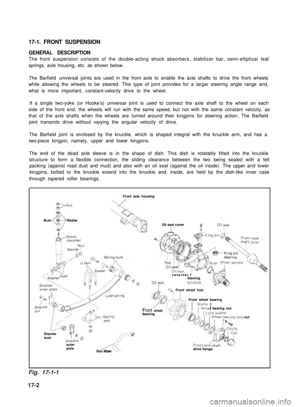
17-1. FRONT SUSPENSION
GENERAL DESCRIPTION
The front suspension consists of the double-acting shock absorbers, stabilizer bar, semi-elliptical leaf
springs, axle housing, etc. as shown below.
The Barfield universal joints are used in the front axle to enable the axle shafts to drive the front wheels
while allowing the wheels to be steered. This type of joint provides for a larger steering angle range and,
what is more important, constant-velocity drive to the wheel.
If a single two-yoke (or Hooke’s) universal joint is used to connect the axle shaft to the wheel on each
side of the front end, the wheels will run with the same speed, but not with the same constant velocity, as
that of the axle shafts when the wheels are turned around their kingpins for steering action. The Barfield
joint transmits drive without varying the angular velocity of drive.
The Barfield joint is enclosed by the knuckle, which is shaped integral with the knuckle arm, and has a
two-piece kingpin, namely, upper and lower kingpins.
The end of the dead axle sleeve is in the shape of dish. This dish is rotatably fitted into the knuckle
structure to form a flexible connection, the sliding clearance between the two being sealed with a felt
packing (against road dust and mud) and also with an oil seal (against the oil inside). The upper and lower
kingpins, bolted to the knuckle extend into the knuckle and, inside, are held by the dish-like inner case
through tapered roller bearings.
BushWasher
Front axle housing
Oil seal cover
retainer ISteeringLn,,rlrlo
Front wheel hub
Front wheel bearing
1\;lEkl bearing nutFront wheelbearina
Shacklebush
outerplateASta ilizer\drive flange
nut
Fig. 17-1-1
17-2