1987 SUZUKI GRAND VITARA oil type
[x] Cancel search: oil typePage 365 of 962

18-1. GENERAL DESCRIPTION
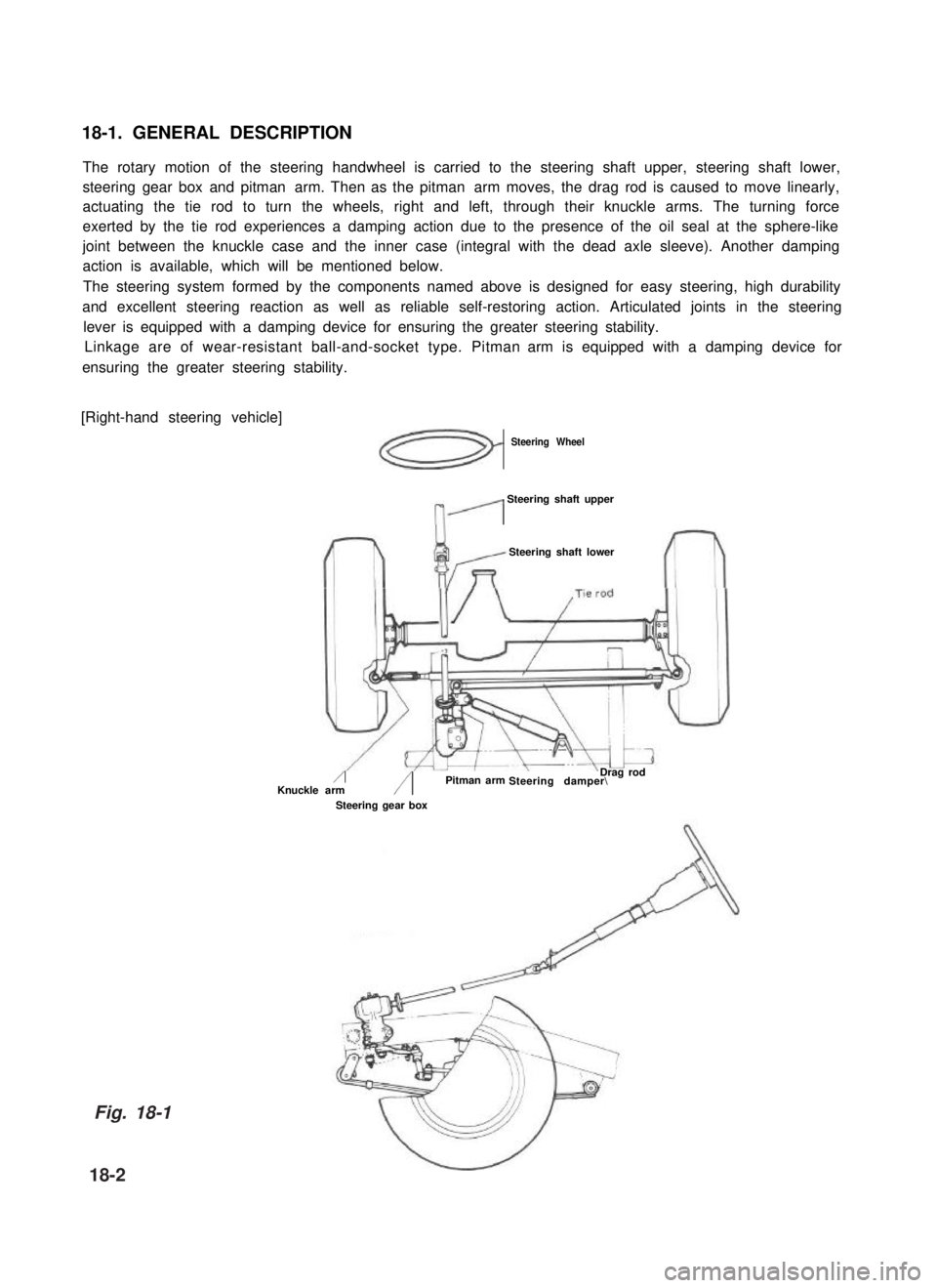
The rotary motion of the steering handwheel is carried to the steering shaft upper, steering shaft lower,
steering gear box and pitman arm. Then as the pitman arm moves, the drag rod is caused to move linearly,
actuating the tie rod to turn the wheels, right and left, through their knuckle arms. The turning force
exerted by the tie rod experiences a damping action due to the presence of the oil seal at the sphere-like
joint between the knuckle case and the inner case (integral with the dead axle sleeve). Another damping
action is available, which will be mentioned below.
The steering system formed by the components named above is designed for easy steering, high durability
and excellent steering reaction as well as reliable self-restoring action. Articulated joints in the steering
lever is equipped with a damping device for ensuring the greater steering stability.
Linkage are of wear-resistant ball-and-socket type. Pitman arm is equipped with a damping device for
ensuring the greater steering stability.
[Right-hand steering vehicle]
Steering Wheel
n’
Steering shaft upper
Steering shaft lower
/Knuckle arm/Steering damper\ Pitman arm
Steering gear box
Drag rod
Fig. 18-1
18-2
Page 382 of 962

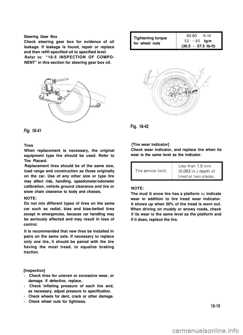
Steering Gear Box
Check steering gear box for evidence of oil
leakage. If leakage is found, repair or replace
and then refill specified oil to specified level.
Refer to“18-5 INSPECTION OF COMPO-
NENT” in this section for steering gear box oil.
Tightening torque
for wheel nuts
50-80 N.m
5.0 - 8.0 kg-m
(36.5 - 57.5 lb-ft)
Fig. 18-42
Fig. 18-41
Tires[Tire wear indicator]
When replacement is necessary, the original
equipment type tire should be used. Refer to
Tire Placard.
Check wear indicator, and replace tire when its
wear is the same level as the indicator.
Replacement tires should be of the same size,
load range and construction as those originally
on the car. Use of any other size or type tire
may affect ride, handling, speedometer/odometer
calibration, vehicle ground clearance and tire or
snow chain clearance to body and chassis.
NOTE:
NOTE:
Do not mix different types of tires on the same
car such as radial, bias and bias-belted tires
except in emergencies, because car handling may
be seriously affected and may result in loss of
control.
The mud & snow tire has a platform ttr indicate
wear in addition to tire tread wear indicator.
It shows up when 50% of tire tread is worn out.
When driving on muddy or snowy roads, check
if its wear is the same level as the platform and
if it does, replace the tire.
It is recommended that new tires be installed in
pairs on the same axle. If necessary to replace
only one tire, it should be paired with the tire
having the most tread, to equalize braking
traction.
[Inspection]
l Check tires for uneven or excessive wear, or
damage. If defective, replace.
l Check inflating pressure of each tire and,
as necessary, adjust pressure to specification.
l Check wheels for dent, crack or other damage.
l Check wheel nuts for tightness.
18-19
Page 392 of 962
![SUZUKI GRAND VITARA 1987 Service Repair Manual [Caliper OPERATION]
Single piston floating caliper type
The single piston floating caliper type brake is
employed in this model. One cylinder and one
piston are used for this type. (The cylinder is
co SUZUKI GRAND VITARA 1987 Service Repair Manual [Caliper OPERATION]
Single piston floating caliper type
The single piston floating caliper type brake is
employed in this model. One cylinder and one
piston are used for this type. (The cylinder is
co](/manual-img/20/57437/w960_57437-391.png)
[Caliper OPERATION]
Single piston floating caliper type
The single piston floating caliper type brake is
employed in this model. One cylinder and one
piston are used for this type. (The cylinder is
constructed as a monoblock with the caliper.)
Fluid pressure generated in the cylinder causes
the pad (1) on the piston side to press against
the disc. At the same time, the floating type
caliper body is moved to the right by the cylin-
der pressure, as shown in below figure, which
pulls pad (2) against the disc and so brakes the
wheel.
Caliper body
\Brake disc (rotor)
Fig. 19-6 - ’
The disc brake has no servo assistance as in drum
braking, and it is necessary to increase the work-
ing pressure of the piston and pad. For this pur-
pose, the wheel cylinder has a large bore. Even
only a little change in clearance between the disc
and pad has therefore a large influence on the
brake pedal stroke. It is necessary to have the
clearance adjusted to the minimum at all times,
by means of the piston (rubber) seal.
Piston seal (Rubber seal)Piston sealWinder (Rubber seal)
II
IPiston
Hydraulic pressure
“OFF“
Fig. 19-7
Clearance correction
Piston
Hydraulic pressure
“ON”
When oil pressure is applied to the piston, the
piston moves forward. The rubber seal, which
exerts considerable pressure against the piston,
moves with the cylinder. However, as a part of
the rubber seal has been fixed into a groove in
the cylinder, the shape of the rubber seal is dis-
torted toward internal end of the cylinder, as
shown in above figure. When pressure is taken
off from the foot brake pedal and fluid pressure
is released from the piston, a restoring force is
generated at the seal and pushes the piston back.
As the pads wear away and the clearance be-
tween the disc and pads becomes larger, the
piston moves a larger distance. The seal then
could change in shape further but, since the end
of the seal is fixed into the groove in the cylin-
der, the distortion is limited to the same amount
as previously described. The piston moves
further to cover the distance of clearance. The
piston returns by the same distance and the
rubber seal recovers its shape as described
above and thus the clearance between the disc
and pads are maintained in adjustment.
19-7
Cylinder
Page 456 of 962

21-4. WINDSHIELD WIPER MOTOR
CIRCUIT DESCRIPTION
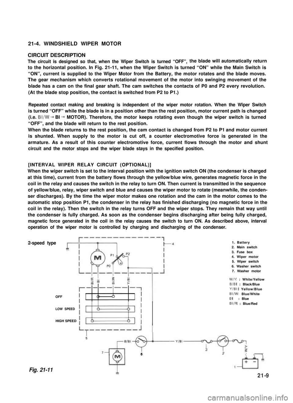
The circuit is designed so that, when the Wiper Switch is turned “OFF”,the blade will automatically return
to the horizontal position. In Fig. 21-11, when the Wiper Switch is turned “ON” while the Main Switch is
“ON”, current is supplied to the Wiper Motor from the Battery, the motor rotates and the blade moves.
The gear mechanism which converts rotational movement of the motor into swinging movement of the
blade has a cam on the final gear shaft. The cam switches the contacts of P0 and P2 every revolution.
(At the blade stop position, the contact is switched from P2 to P1.)
Repeated contact making and breaking is independent of the wiper motor rotation. When the Wiper Switch
is turned “OFF” while the blade is in a position other than the rest position, motor current path is changed
(i.e. BI/W + BI + MOTOR). Therefore, the motor keeps rotating even though the wiper switch is turned
“OFF”, and the blade will return to the rest position.
When the blade returns to the rest position, the cam contact is changed from P2 to P1 and motor current
is shunted. When supply to the motor is cut off, a counter electromotive force is generated in the
armature. As a result of this counter electromotive force, current flows through the motor and shunt
circuit and the motor stops and the wiper blade stays in the specified position.
[INTERVAL WIPER RELAY CIRCUIT (OPTIONAL)]
When the wiper switch is set to the interval position with the ignition switch ON (the condenser is charged
at this time), current from the battery flows through the yellow/blue wire, generates magnetic force in the
coil in the relay and causes the switch in the relay to turn ON. Then current is transmitted in the sequence
of yellow/blue, relay, wiper switch and blue and causes the wiper motor to rotate (meanwhile, the conden-
ser discharges). By the time the wiper motor makes one rotation and the cam in the motor comes to the
automatic stop position P1, the condenser in the relay has finished discharging (no magnetic force in the
coil in the relay). Then the switch in the relay turns OFF and the wiper stops. They remain that way until
the condenser is fully charged. As soon as the condenser begins discharging after being fully charged,
magnetic force generated in the coil in the relay causes the switch to turn ON. As described above, interval
operation of the wiper motor is controlled by charging and discharging of the condenser.
2-speed type
OFF
1. Battery2. Main switch
3. Fuse box4. Wiper motor5. Wiper switch
6. Washer switch7. Washer motor
W/Y : White/Yellow
B/BI : Black/Blue
Y/El: Yellow/Blue
BI/W: Blue/WhiteBI: Blue
LOW SPEED
BIIR : Blue/Red
HIGH SPEED
Fig. 21-11
6
21-9
Page 472 of 962

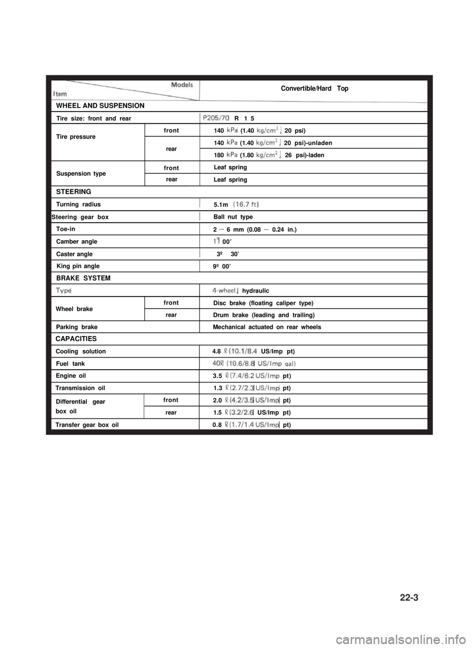
Convertible/Hard Top
WHEEL AND SUSPENSIONI
Tire size: front and rear1 P205/70 R15I
Tire pressurefront
rear
Suspension typefront
rear
140 kPa (1.40 kg/cm’, 20 psi)
140 kPa (1.40 kg/cm’, 20 psi)-unladen
180 kPa (1.80 kg/cm*, 26 psi)-laden
Leaf spring
Leaf spring
STEERING
Turning radius1 5.1 m (16.7ft)
1 Steering gear box1Ball nut typeI
Toe-in
Camber angle
Caster angle
King pin angle
BRAKE SYSTEM
Type
Wheel brake
Parking brake
CAPACITIES
Cooling solution
Fuel tank
2 - 6 mm (0.08 - 0.24 in.)
lo 00’
) 3º 30’I
front
rear
9º 00’
4-wheel, hydraulic
Disc brake (floating caliper type)
Drum brake (leading and trailing)
Mechanical actuated on rear wheels
4.8 Q (10.1/8.4 US/Imp pt)
4OQ (10.6/8.8 US/Imp cral)
Engine oil
Transmission oil
Differential gear
box oil
Transfer gear box oil
front
rear
3.5 II (7.4/6.2 US/Imp pt)
1.3 II (2.7/2.3 US/Imp pt)
2.0 Q (4.2/3.5 US/Imp pt)
1.5 II (3.2/2.6 US/Imp pt)
0.8 !? (1.7/l .4 US/Imp pt)
22-3