1987 SUZUKI GRAND VITARA coolant reservoir
[x] Cancel search: coolant reservoirPage 23 of 962
NOTE:
Steps 1) - 6) outlined above must be performed
with ENGINE NOT RUNNING. For step 7),
be sure to have adequate ventilation while
engine is running
It is recommended to use engine oil of SE or
SF class.
NOTE:For temperatures below
32”F(O”C), it is highly
recommended to use SAE 5W-30 oil.
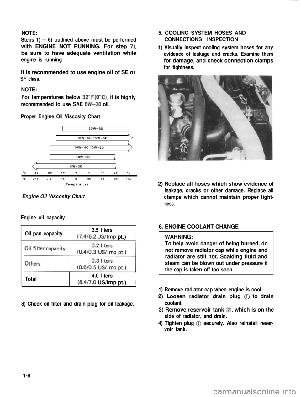
Proper Engine Oil Viscosity Chart
12OW-50
lSW-40.15w-501
Ilow-4O.lOW-50
Ilow-30I
5w-30I“C-3 0 -2
0 -1
0 0 102
0
30 4
0
OF-2 2 -
4 14
32506886104
Temperatur e
Engine Oil Viscosity Chart
Engine oil capacity
Oil pan capacity 3.5 liters (7.4/6.2
US/Imp pt.)I
Total 4.0 liters(8.4/7.0 US/Imp pt.)I
8) Check oil filter and drain plug for oil leakage.
5. COOLING SYSTEM HOSES AND
CONNECTIONS INSPECTION
1) Visually inspect cooling system hoses for any
evidence of leakage and cracks. Examine them
for damage, and check connection clamps
for tightness.
2) Replace all hoses which show evidence of
leakage, cracks or other damage. Replace all
clamps which cannot maintain proper tight-
ness.
6. ENGINE COOLANT CHANGE
WARNING:
To help avoid danger of being burned, do
not remove radiator cap while engine and
radiator are still hot. Scalding fluid and
steam can be blown out under pressure if
the cap is taken off too soon.
1) Remove radiator cap when engine is cool.
2) Loosen radiator drain plug @
to drain
coolant.
3) Remove reservoir tank 0, which is on the
side of radiator, and drain.
4) Tighten plug
@ securely. Also reinstall reser-
voir tank.
1-8
Page 25 of 962
CAUTION:
When changing engine coolant, use mixture
of 56% water and 50% GOLDEN CRUISER
1200for the market where ambient tem-
perature falls lower than -16°C (3°F) in
winter and mixture of 70% water and
30% GOLDEN CRUISER 1200for the
market where ambient temperature doesn’t
fall lower than -16°C (3” F).
Even in a market where no freezing tempe-
rature is anticipated, mixture of 70% water
and 30% GOLDEN CRUISER 1200
should be used for the purpose of corro-
sion protection and lubrication.
7. EXHAUST PIPES AND MOUNTINGS
INSPECTION
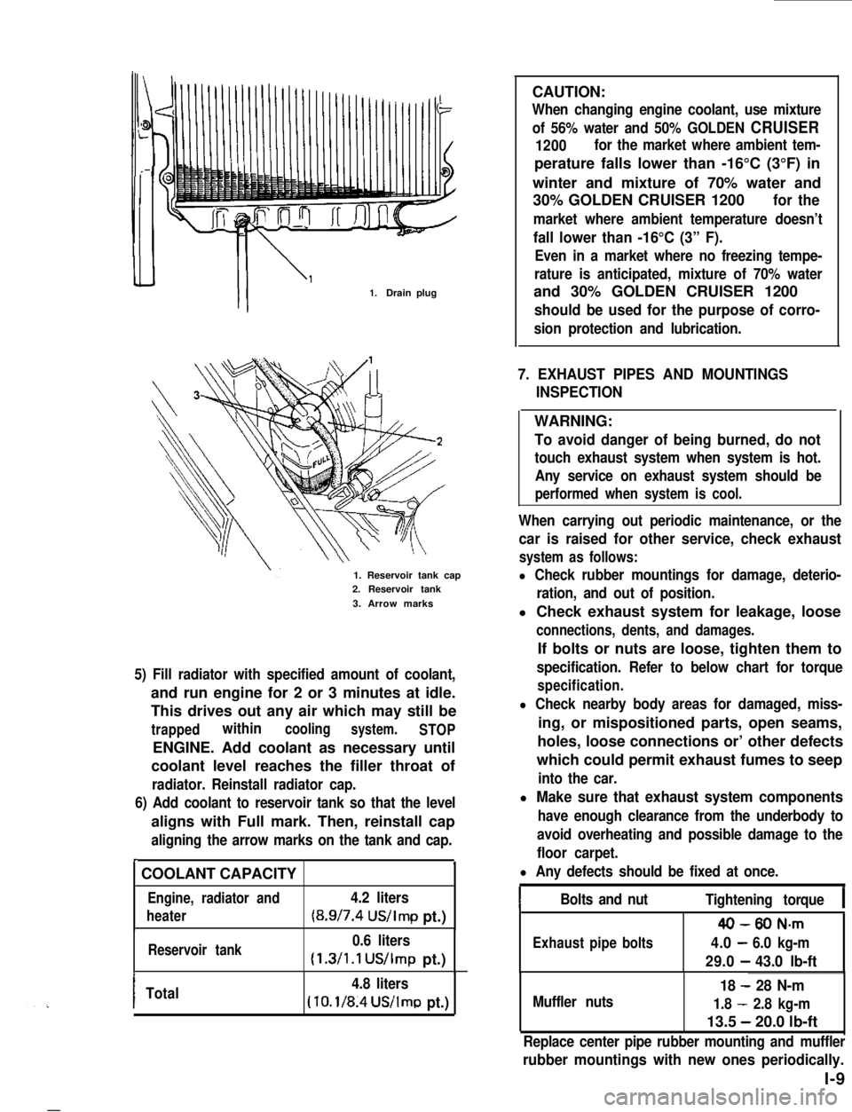
1.Drain plug
1. Reservoir tank cap2. Reservoir tank
3. Arrow marks
5) Fill radiator with specified amount of coolant,
and run engine for 2 or 3 minutes at idle.
This drives out any air which may still be
trappedwithincoolingsystem.STOP
ENGINE. Add coolant as necessary until
coolant level reaches the filler throat of
radiator. Reinstall radiator cap.
6) Add coolant to reservoir tank so that the level
aligns with Full mark. Then, reinstall cap
aligning the arrow marks on the tank and cap.
r.
COOLANT CAPACITY
Engine, radiator and4.2 liters
heater(8.9/7.4 US/Imp pt.)
Reservoir tank0.6 liters
(1.3/1.1 US/Imp pt.)
ITotal4.8 liters
(10.1/8.4US/lmp pt.)
WARNING:
To avoid danger of being burned, do not
touch exhaust system when system is hot.
Any service on exhaust system should be
performed when system is cool.
When carrying out periodic maintenance, or the
car is raised for other service, check exhaust
system as follows:
l Check rubber mountings for damage, deterio-
ration, and out of position.
l Check exhaust system for leakage, loose
connections, dents, and damages.
If bolts or nuts are loose, tighten them to
specification. Refer to below chart for torque
specification.
l Check nearby body areas for damaged, miss-
ing, or mispositioned parts, open seams,
holes, loose connections or’ other defects
which could permit exhaust fumes to seep
into the car.
l Make sure that exhaust system components
have enough clearance from the underbody to
avoid overheating and possible damage to the
floor carpet.
l Any defects should be fixed at once.
IBolts and nutTightening torqueI
40-80 N-m
Exhaustpipebolts4.0-6.0 kg-m
29.0-43.0 lb-ft
Muffler nuts
18 - 28 N-m
1.8 - 2.8 kg-m
13.5 - 20.0 lb-ft
Replace center pipe rubber mounting and muffler
rubber mountings with new ones periodically.
l-9
Page 192 of 962
6-l. GENERAL DESCRIPTION
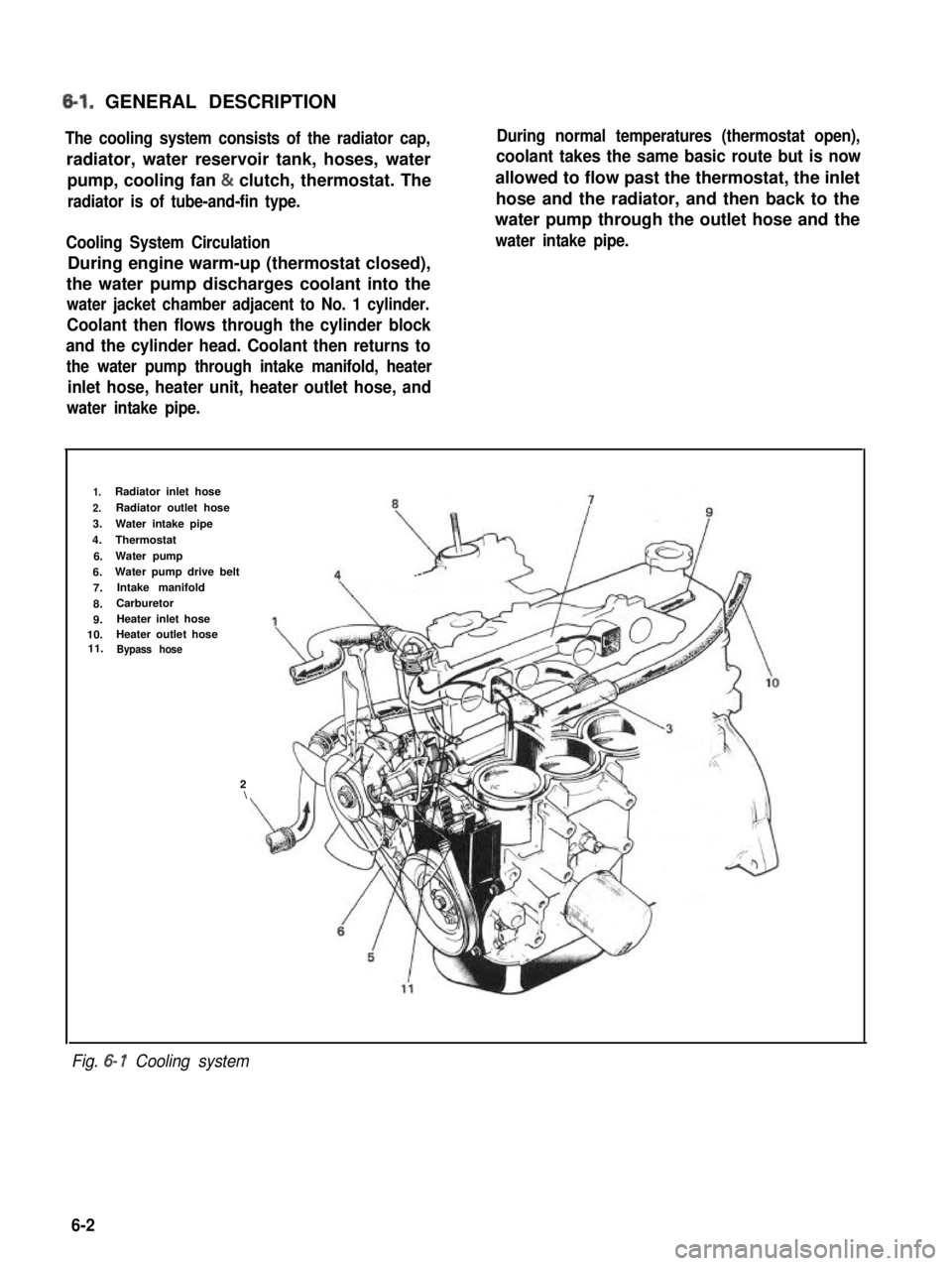
The cooling system consists of the radiator cap,
radiator, water reservoir tank, hoses, water
pump, cooling fan & clutch, thermostat. The
radiator is of tube-and-fin type.
Cooling System Circulation
During engine warm-up (thermostat closed),
the water pump discharges coolant into the
water jacket chamber adjacent to No. 1 cylinder.
Coolant then flows through the cylinder block
and the cylinder head. Coolant then returns to
the water pump through intake manifold, heater
inlet hose, heater unit, heater outlet hose, and
water intake pipe.
During normal temperatures (thermostat open),
coolant takes the same basic route but is now
allowed to flow past the thermostat, the inlet
hose and the radiator, and then back to the
water pump through the outlet hose and the
water intake pipe.
1.Radiator inlet hose
2.Radiator outlet hose
3.Water intake pipe
4.Thermostat
6.Water pump
6.Water pump drive belt
7.Intake manifold
8.Carburetor
9.Heater inlet hose10.Heater outlet hose11.Bypass hose
2\
Fig. 6- 1 Cooling system
6-2
Page 193 of 962
Radiator Cap
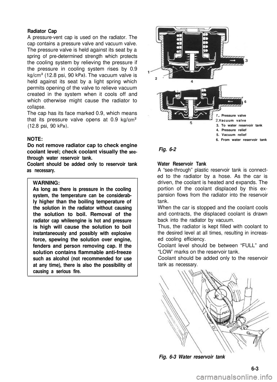
A pressure-vent cap is used on the radiator. The
cap contains a pressure valve and vacuum valve.
The pressure valve is held against its seat by a
spring of pre-determined strength which protects
the cooling system by relieving the pressure if
the pressure in cooling system rises by 0.9
kg/cm2 (12.8 psi, 90 kPa). The vacuum valve is
held against its seat by a light spring which
permits opening of the valve to relieve vacuum
created in the system when it cools off and
which otherwise might cause the radiator to
collapse.
The cap has its face marked 0.9, which means
that its pressure valve opens at 0.9 kg/cm2
(12.8 psi, 90 kPa).
NOTE:
Do not remove radiator cap to check engine
coolant level; check coolant visually the see-
through water reservoir tank.
Coolant should be added only to reservoir tank
as necessary.
4
WARNING:
As long as there is pressure in the cooling
system, the temperature can be considerab-
ly higher than the boiling temperature of
the solution in the radiator without causing
the solution to boil. Removal of the
radiator cap whileengine is hot and pressure
is high will cause the solution to boil
instantaneously and possibly with explosive
force, spewing the solution over engine,
fenders and person removing cap. If the
solution contains flammable anti-freeze
such as alcohol (not recommended for use
at any time), there is also the possibility of
causing a serious fire.
2’
I6
. Pressure valve
Vacuum valve
3. To water reservoir tank4. Pressure relief5. Vacuum relief
6. From water reservoir tank
Fig. 6-2
Water Reservoir Tank
A “see-through” plastic reservoir tank is connect-
ed to the radiator by a hose. As the car is
driven, the coolant is heated and expands. The
portion of the coolant displaced by this ex-
pansion flows from the radiator into the reservoir
tank.
When the car is stopped and the coolant cools
and contracts, the displaced coolant is drawn
back into the radiator by vacuum.
Thus, the radiator is kept filled with coolant to
the desired level at all times, resulting in increas-
ed cooling efficiency.
Coolant level should be between “FULL” and
“LOW’ marks on the reservoir tank.
Coolant should be added only to the reservoir
tank as necessary.
Fig. 6-3 Water reservoir tank
6-3
Page 201 of 962
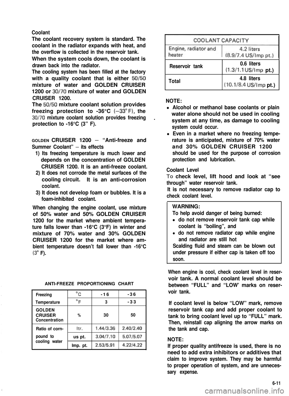
Coolant
The coolant recovery system is standard. The
coolant in the radiator expands with heat, and
the overflow is collected in the reservoir tank.
When the system cools down, the coolant is
drawn back into the radiator.
The cooling system has been filled at the factory
with a quality coolant that is either 50/50
mixture of water and GOLDEN CRUISER
1200 or 30/70 mixture of water and GOLDEN
CRUISER 1200.
The 50/50 mixture coolant solution provides
freezing protection to -36°C (-33”F), the
30/70 mixture coolant solution provides freezing.
protection to -16°C (3” F).
GOLDEN CRUISER 1200 - “Anti-freeze and
Summer Coolant” - its effects
1) Its freezing temperature is much lower and
depends on the concentration of GOLDEN
CRUISER 1200. It is an anti-freeze coolant.
2) It does not corrode the metal surfaces of the
cooling circuit.It is an anti-corrosion
coolant.
3) It does not develop foam or bubbles. It is a
foam-inhibited coolant.
When changing the engine coolant, use mixture
of 50% water and 50% GOLDEN CRUISER
1200 for the market where ambient tempera-
ture falls lower than -16°C (3°F) in winter and
mixture of 70% water and 30% GOLDEN
CRUISER 1200 for the market where am-
bient temperature doesn’t fall lower than -16°C
(3” F).
ANTI-FREEZE PROPORTIONING CHART
Freezing
Temperature
GOLDEN
CRUISERConcentration
OC-16-36
OF3-33
%3050
Ratio of corn-Itr.1.4413.362.4012.40
pound tous pt.3.04l7.10 5.0715.07cooling waterImp. pt.2.5315.914.221422
Reservoir tank0.6 liters
(1.3/1.1 US/Imp pt.)I
Total4.8 liters
(10.1/8.4 US/Imp pt.)
NOTE:
l Alcohol or methanol base coolants or plain
water alone should not be used in cooling
system at any time, as damage to cooling
system could occur.
l Even in a market where no freezing tempe-
rature is anticipated, mixture of 70% water
and 30% GOLDEN CRUISER 1200
should be used for the purpose of corrosion
protection and lubrication.
Coolant Level
,To check level, lift hood and look at “see
through” water reservoir tank.
It is not necessary to remove radiator cap to
check coolant level.
WARNING:
To help avoid danger of being burned:
l do not remove reservoir tank cap while
coolant is “boiling”, and
l do not remove radiator cap while engine
and radiator are still hot
Scalding fluid and steam can be blown out
under pressure if either cap is taken off too
soon.
When engine is cool, check coolant level in reser-
voir tank. A normal coolant level should be
between “FULL” and “LOW’ marks on reser-
voir tank.
If coolant level is below “LOW” mark, remove
reservoir tank cap and add proper coolant to
tank to bring coolant level up to “FULL” mark.
Then, reinstall cap aligning the arrow marks on
the tank and cap.
NOTE:
If proper quality antifreeze is used, there is no
need to add extra inhibitors or additives that
claim to improve system. They may be harmful
to proper operation of system, and are unneces-
sary expense.
6-11
Page 202 of 962
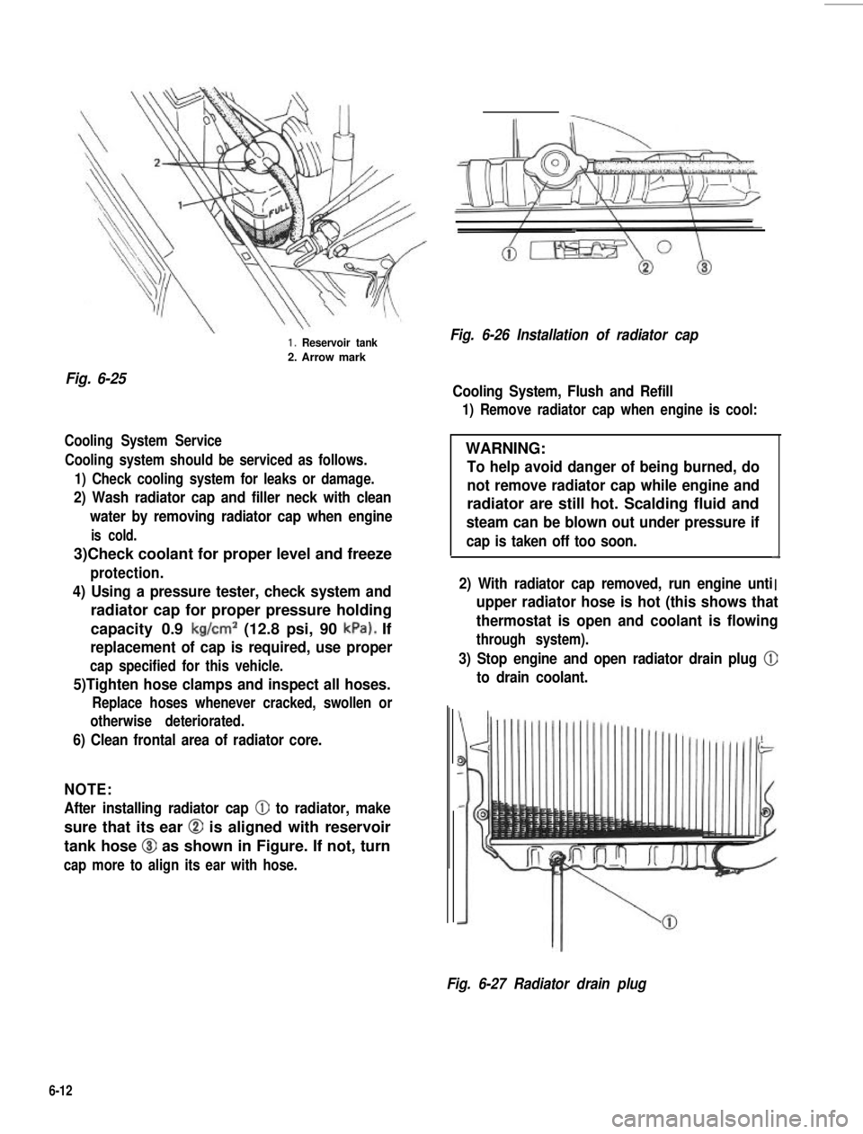
Fig. 6-25
1. Reservoir tank
2. Arrow mark
Cooling System Service
Cooling system should be serviced as follows.
1) Check cooling system for leaks or damage.
2) Wash radiator cap and filler neck with clean
water by removing radiator cap when engine
is cold.
3)Check coolant for proper level and freeze
protection.
4) Using a pressure tester, check system and
radiator cap for proper pressure holding
capacity 0.9 kg/cm2 (12.8 psi, 90 kPa). If
replacement of cap is required, use proper
cap specified for this vehicle.
5)Tighten hose clamps and inspect all hoses.
Replace hoses whenever cracked, swollen or
otherwise deteriorated.
6) Clean frontal area of radiator core.
NOTE:
After installing radiator cap 0 to radiator, make
sure that its ear @ is aligned with reservoir
tank hose @I as shown in Figure. If not, turn
cap more to align its ear with hose.
Fig. 6-26 Installation of radiator cap
Cooling System, Flush and Refill
1) Remove radiator cap when engine is cool:
WARNING:
To help avoid danger of being burned, do
not remove radiator cap while engine and
radiator are still hot. Scalding fluid and
steam can be blown out under pressure if
cap is taken off too soon.d
I2) With radiator cap removed, run engine unti. .upper radiator hose is hot (this shows that
thermostat is open and coolant is flowing
through system).
3) Stop engine and open radiator drain plug @
to drain coolant.
Fig. 6-27 Radiator drain plug
6-12
Page 203 of 962
4) Close drain plug. Add water until system is
filled and run engine until upper radiator
hose is hot again.
5) Repeat steps 3) and 4) several times until
drained liquid is nearly colorless.
6) Drain system and then close radiator drain
plug tightly.
7) Disconnect hose from water reservoir tank.
Remove tank and pour out any fluid. Scrub
and clean inside of tank with soap and water.
Flush it well with clean water and drain.
Reinstall tank and hose.
8)Add proper mixture coolant (refer to page
6-11 of GOLDEN CRUISER 1200 and _,
water to radiator and tank.
Fill radiator to the base of radiator filler
neck and reservoir tank to “FULL” level
mark. Reinstall reservoir tank cap, aligning
the arrow marks on the tank and cap.
9) Run engine, with rediator cap removed, until
radiator upper hose is hot.
10) With engine idling, add coolant to radiator
until level reaches the bottom of filler neck.
Install radiator cap, making sure that the ear
of cap lines up with reservoir tank hose.
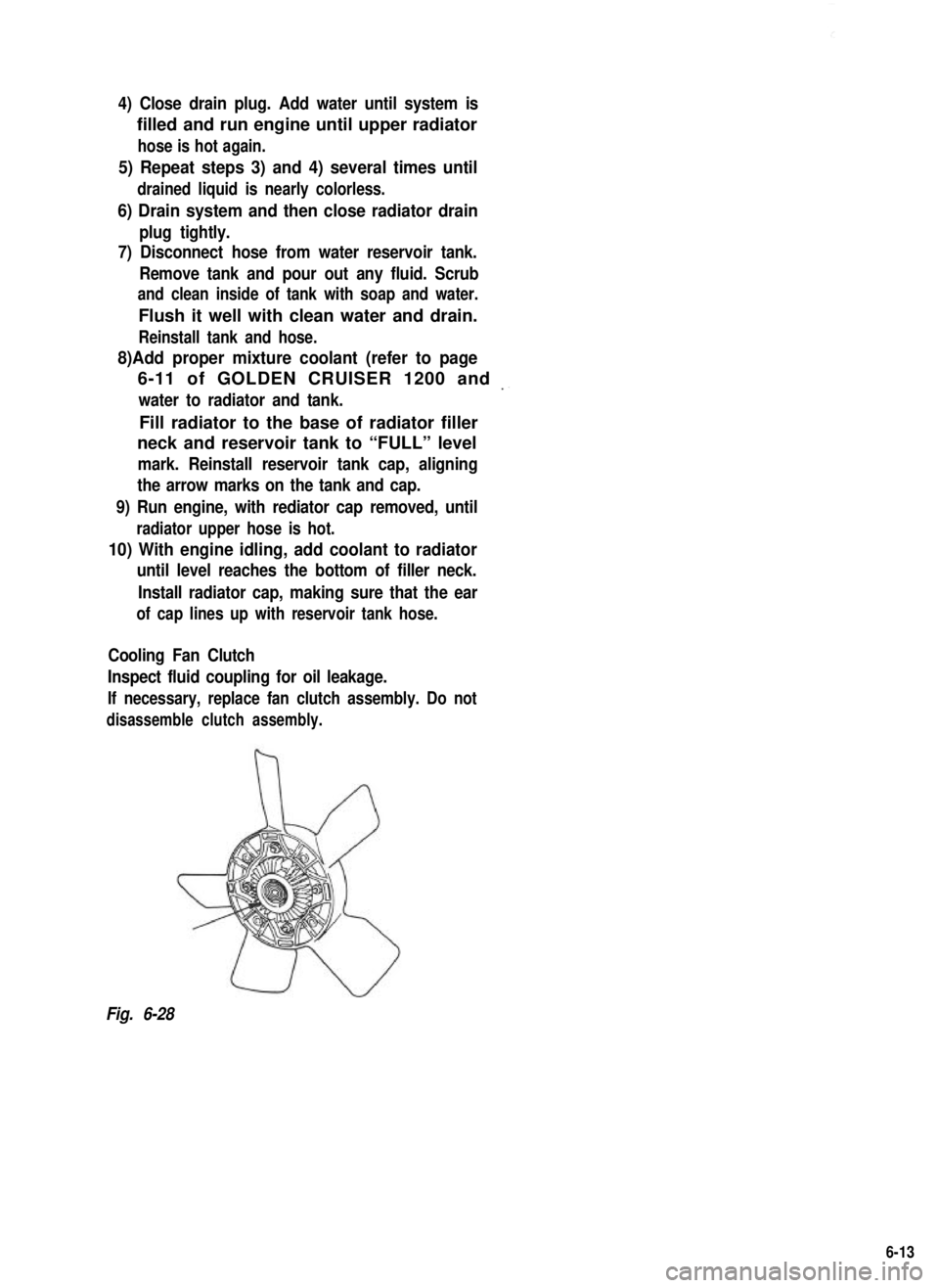
Cooling Fan Clutch
Inspect fluid coupling for oil leakage.
If necessary, replace fan clutch assembly. Do not
disassemble clutch assembly.
Fig. 6-28
6-13