1987 SUZUKI GRAND VITARA run flat
[x] Cancel search: run flatPage 380 of 962

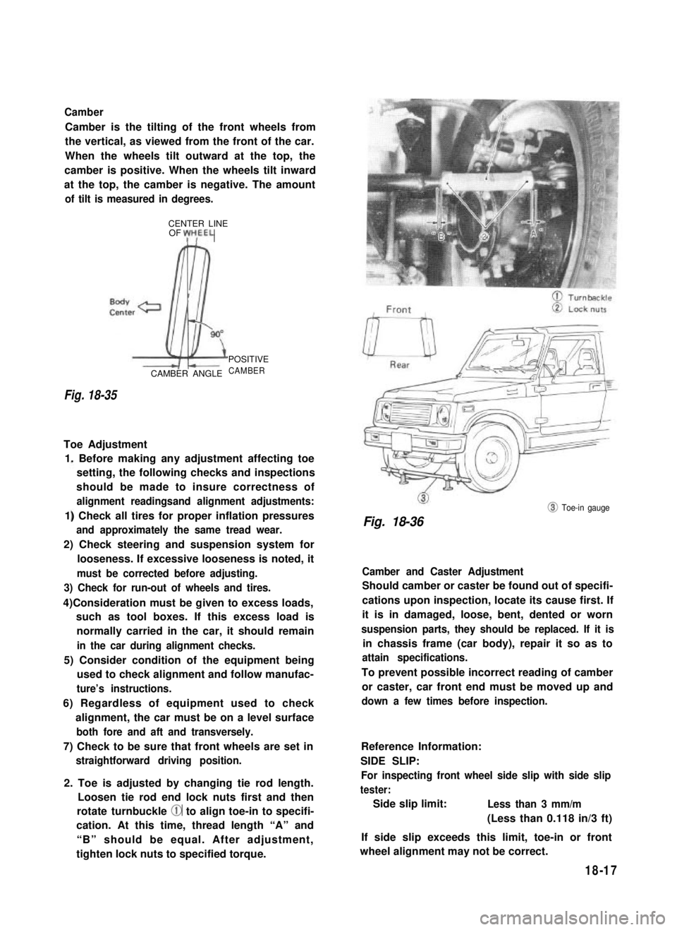
Camber
Camber is the tilting of the front wheels from
the vertical, as viewed from the front of the car.
When the wheels tilt outward at the top, the
camber is positive. When the wheels tilt inward
at the top, the camber is negative. The amount
of tilt is measured in degrees.
CENTER LINEOF yH,EEL
Fig. 18-35
CAMBER ANGLE
‘POSITIVE
CAMBER
Toe Adjustment
1. Before making any adjustment affecting toe
setting, the following checks and inspections
should be made to insure correctness of
alignment readingsand alignment adjustments:
1) Check all tires for proper inflation pressures
and approximately the same tread wear.
2) Check steering and suspension system for
looseness. If excessive looseness is noted, it
must be corrected before adjusting.
3) Check for run-out of wheels and tires.
4)Consideration must be given to excess loads,
such as tool boxes. If this excess load is
normally carried in the car, it should remain
in the car during alignment checks.
5) Consider condition of the equipment being
used to check alignment and follow manufac-
ture’s instructions.
6) Regardless of equipment used to check
alignment, the car must be on a level surface
both fore and aft and transversely.
7) Check to be sure that front wheels are set in
straightforward driving position.
2. Toe is adjusted by changing tie rod length.
Loosen tie rod end lock nuts first and then
rotate turnbuckle @ to align toe-in to specifi-
cation. At this time, thread length “A” and
“B” should be equal. After adjustment,
tighten lock nuts to specified torque.
@ Toe-in gauge
Fig. 18-36
Camber and Caster Adjustment
Should camber or caster be found out of specifi-
cations upon inspection, locate its cause first. If
it is in damaged, loose, bent, dented or worn
suspension parts, they should be replaced. If it is
in chassis frame (car body), repair it so as to
attain specifications.
To prevent possible incorrect reading of camber
or caster, car front end must be moved up and
down a few times before inspection.
Reference Information:
SIDE SLIP:
For inspecting front wheel side slip with side slip
tester:
Side slip limit:Less than 3 mm/m
(Less than 0.118 in/3 ft)
If side slip exceeds this limit, toe-in or front
wheel alignment may not be correct.
18-17
Page 383 of 962
![SUZUKI GRAND VITARA 1987 Service Repair Manual Fig. 18-43 @ Tire tread wear indicator
@ Wear indicating platform
[ Inflation of tires]
l Tire inflation pressures are listed on the
Tire Placard at driver’s side of instrument
panel.
l Tire inflati SUZUKI GRAND VITARA 1987 Service Repair Manual Fig. 18-43 @ Tire tread wear indicator
@ Wear indicating platform
[ Inflation of tires]
l Tire inflation pressures are listed on the
Tire Placard at driver’s side of instrument
panel.
l Tire inflati](/manual-img/20/57437/w960_57437-382.png)
Fig. 18-43 @ Tire tread wear indicator
@ Wear indicating platform
[ Inflation of tires]
l Tire inflation pressures are listed on the
Tire Placard at driver’s side of instrument
panel.
l Tire inflation pressures should be checked
(including spare tire) at least monthly and
when significantly changing the load in the
car.
l Always check tire inflation pressures when
tires are “cold”.
l Always use tire pressure gauge when checking
inflation pressure.
l Be sure to reinstall tire inflation valve caps to
prevent dirt and moisture from getting into
valve core, as they may cause air leakage.
l If air loss occurs while driving, do not drive
on the deflated tire more than is needed to
stop safety. Driving even a short distance on a
deflated tire can damage a tire and wheel
beyond repair.
NOTE:
Before installing wheels, remove any build-up of
corrosion on the wheel mounting surface and
brake drum or disc mounting surface by scraping
and wire brushing. Installing wheels without
good metal-to-metal contact at the mounting
surfaces can cause wheel nuts to loosen, which
can later allow a wheel to come off while the
car is moving.
RADIAL TIRES
.i II
9T
\
I
4-wheels
Fig. 18-44
fT
u
[I
5-wheels
[Wheels]
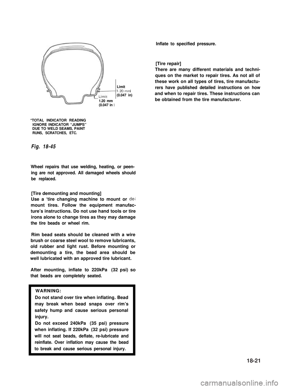
Wheels must be replaced if they are bent, dented,
have excessive lateral or radial runout, leak air
through welds, have elongated bolt holes, if
lug nuts won’t stay tight, or if they are heavily
rusted. Wheels with greater runout than shown
in below figure may cause objectional vibrations.
Replacement wheels must be equivalent to the
original equipment wheels in load capacity,
diameter,rim width, offset and mounting
configuration. A wheel of improper size or type
may affect wheel and bearing life, brake cooling,
speedometer/odometer calibration, car ground
clearance and tire clearance to the body and
chassis.
[Tire rotation]
“Rotate” tires at the regular intervals in order to
equalize tire wear and thereby make full use of
each tire. Refer to below figure for the scheme
of rotation. Adherence to this scheme prolongs
tire life.
18-20
Page 384 of 962

/I
d-
Limitl.Mmm(0.047 in)
1.20 mm(0.047 in 1
*TOTAL INDICATOR READINGIGNORE INDICATOR “JUMPS”DUE TO WELD SEAMS, PAINTRUNS, SCRATCHES, ETC.
Fig. 18-45
Wheel repairs that use welding, heating, or peen-
ing are not approved. All damaged wheels should
be replaced.
[Tire demounting and mounting]
Use a ‘tire changing machine to mount or de-
mount tires. Follow the equipment manufac-
ture’s instructions. Do not use hand tools or tire
irons alone to change tires as they may damage
the tire beads or wheel rim.
Rim bead seats should be cleaned with a wire
brush or coarse steel wool to remove lubricants,
old rubber and light rust. Before mounting or
demounting a tire, the bead area should be
well lubricated with an approved tire lubricant.
After mounting, inflate to 220kPa (32 psi) so
that beads are completely seated.
WARNING:
Do not stand over tire when inflating. Bead
may break when bead snaps over rim’s
safety hump and cause serious personal
injury.
Do not exceed 240kPa (35 psi) pressure
when inflating. If 220kPa (32 psi) pressure
will not seat beads, deflate, re-lubricate and
reinflate. Over inflation may cause the bead
to break and cause serious personal injury.1
Inflate to specified pressure.
[Tire repair]
There are many different materials and techni-
ques on the market to repair tires. As not all of
these work on all types of tires, tire manufactu-
rers have published detailed instructions on how
and when to repair tires. These instructions can
be obtained from the tire manufacturer.
18-21
Page 473 of 962

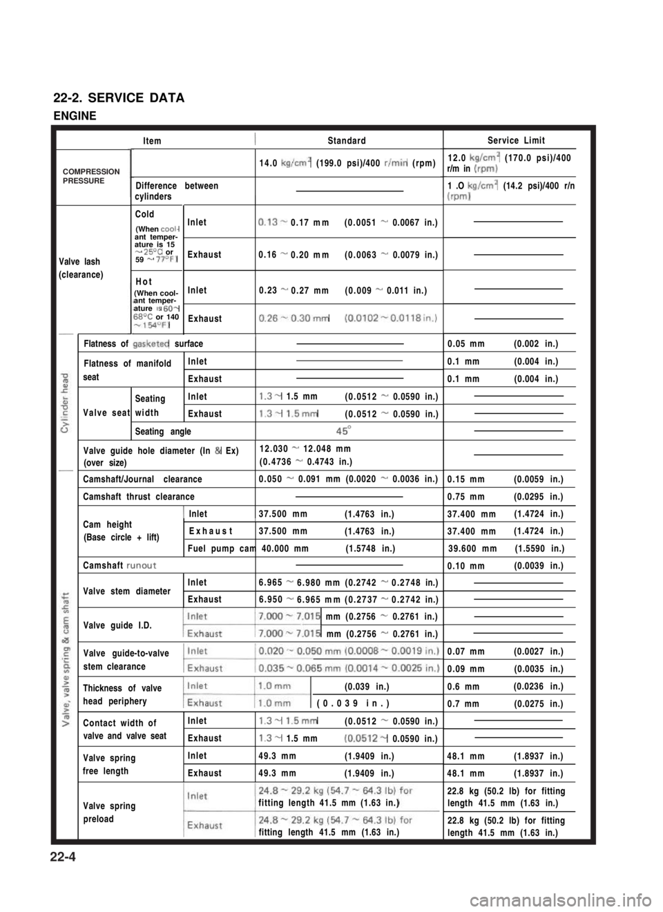
22-2. SERVICE DATA
ENGINE
ItemStandardService Limit
12.0 kg/cm2 (170.0 psi)/400r/m in (rpm)
1 .O kg/cm2 (14.2 psi)/400 r/n
(m-d
14.0 kg/cm2 (199.0 psi)/400 r/min (rpm)
Difference betweencylinders
Cold
(When cooi-ant temper-ature is 15- 25T or59 - 77OF)
Hot
(When cool-ant temper-ature IS 60-68T or 140-154OFJ
Valve lash
(clearance)
Inlet
Exhaust
Inlet
Exhaust
0.13-0.17mm(0.0051 - 0.0067 in.)
0.16 -0.20mm(0.0063 - 0.0079 in.)
0.23 -0.27mm(0.009 - 0.011 in.)
0.26%0.30mm (0.0102-0.0118in.)
/0.05 mm(0.002 in.)Flatness of gasketed surface
Flatness of manifoldInlet
seatExhaust
SeatingInlet
Valve seat widthExhaust
Seating angle
1.3- 1.5 mm(0.0512 - 0.0590 in.)
1.3- 1.5mm(0.0512 - 0.0590 in.)
45O
0.1 mm(0.004 in.)
0.1 mm(0.004 in.)
Valve guide hole diameter (In & Ex)12.030 - 12.048 mm
(over size)(0.4736 - 0.4743 in.)
Camshaft/Journal clearance0.050 - 0.091 mm (0.0020 - 0.0036 in.)0.15 mm(0.0059 in.)
0.75 mm(0.0295 in.)Camshaft thrust clearance
1 Inlet37.500 mm(1.4763 in.)37.400 mm(1.4724 in.)Cam heightI
(Base circle + lift) Exhaust37.500 mm(1.4763 in.)
Fuel pump cam 40.000 mm(1.5748 in.)
37.400 mm(1.4724 in.)
39.600 mm(1.5590 in.)
Camshaft runout0.10 mm(0.0039 in.)
Inlet6.965-6.980mm(0.2742-0.2748in.)Valve stem diameterExhaust6.950-6.965mm(0.2737-0.2742in.)
Valve guide I.D.7.000 - 7.015 mm (0.2756 - 0.2761 in.)
w.015 mm (0.2756 - 0.2761 in.)
Valve guide-to-valve
stem clearance
0.07 mm(0.0027 in.)
0.09 mm(0.0035 in.)
Thickness of valve(0.039 in.)
head peripherymw (0.039 in.)
0.6 mm(0.0236 in.)
0.7 mm(0.0275 in.)
Contact width ofInlet1.3- 1.5mm(0.0512 - 0.0590 in.)
valve and valve seatExhaust1.3- 1.5 mm(0.0512- 0.0590 in.)
48.1 mm(1.8937 in.)Valve spring
free length
Inlet
Exhaust
49.3 mm(1.9409 in.)
49.3 mm(1.9409 in.)48.1 mm(1.8937 in.)
Valve spring
preload
fitting length 41.5 mm (1.63 in.)
fitting length 41.5 mm (1.63 in.)
22.8 kg (50.2 lb) for fitting
length 41.5 mm (1.63 in.)
22.8 kg (50.2 lb) for fitting
length 41.5 mm (1.63 in.)
COMPRESSIONPRESSURE
22-4