1987 SUZUKI GRAND VITARA steering wheel adjustment
[x] Cancel search: steering wheel adjustmentPage 52 of 962

2-9. SUSPENSION, STEERING SYSTEM AND TIRES
Condition
Hard steering
Possible causeCorrection
1. Wheel tires not adequately inflatedAdjust the pressure
2. Bind in tie rod end ball studReplace
3. Linkage connections tending to seizeRepair or replace
4. Steering gearbox out of adjustmentAdjust as prescribed
5. Unevenly worn steering shaft bushReplace
6. Disturbed front wheel alignmentAdjust as prescribed
Wobbly steering wheel1. Wheel tires inflated unequallyAdjust tire pressure
(Shimmy, shake or2. Wobbly wheelsRepair or replace
vibration)3. Large difference in tire diameter betweenReplace._
right and left wheels
4. Loose hub nutsRetighten
5. Damaged or worn wheel bearingsReplace
6. Worn or loose tie rod endsReplace or retighten
7. Steering gearbox out of adjustmentAdjust as prescribed
8. Steering gearbox mounted looseRetighten
9. Worn steering knuckle oil sealReplace
10. Tire or wheel out of balanceBalance wheel or replace tire
and/or wheel
11. Blister or bump on tireReplace tire
12. Disturbed front wheel alignmentCheck front wheel alignment
Steering wheel
pulling to one
side (car pulls)
1. Unevenly worn wheel tires
2. Brake dragging in one road wheel
3. Wheel tires unequally inflated
4. Worn or distorted link rods
5. Disturbed front wheel alignment
6. Loose, bent or broken front or rear
suspension parts
Replace
Repair
Adjust tire pressure
Replace
Adjust as prescribed
Tighten or replace suspension
parts
Shocks coming to1. Tire inflating pressure too highReduce to the specification
steering wheel2. Poor shock absorber performanceReplace
(or wheel tramp)3. Differences in tire diameter among fourAdjust
road wheels
4. Worn steering linkage connectionsReplace
5. Worn or broken front wheel bearingsReplace
6. Loose front wheelRetighten
7. Steering wheel loose in placeRetighten the nut
8. Blister or bump on tireReplace tire
Rapid wear or uneven1. Wheel tires imporperly inflatedAdjust tire pressure
wear of wheel tires2. Differences in diameter among four tiresAdjust or replace
(Abnormal or excessive3. Worn or loose road wheel bearingsReplace
tire wear)4. Wobbly wheel tiresRepair or replace
2-14
Page 53 of 962
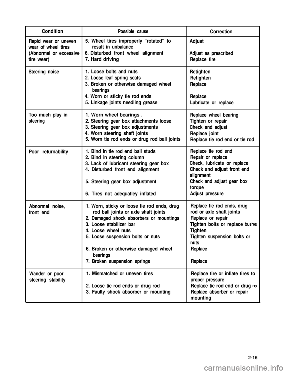
ConditionPossible causeCorrection
Rapid wear or uneven5. Wheel tires improperly “rotated“ toAdjust
wear of wheel tiresresult in unbalance
(Abnormal or excessive6. Disturbed front wheel alignmentAdjust as prescribed
tire wear)7. Hard drivingReplace tire
Steering noise1. Loose bolts and nuts
2. Loose leaf spring seats
3. Broken or otherwise damaged wheel
bearings
4. Worn or sticky tie rod ends
5. Linkage joints needling grease
Retighten
Retighten
Replace
Replace
Lubricate or replace
Too much play in
steering
1. Worn wheel bearings .Replace wheel bearing
2. Steering gear box attachments looseTighten or repair
3. Steering gear box adjustmentsCheck and adjust
4. Worn steering shaft jointsReplace joint
5. Worn tie rod ends or drug rod ball jointsReplace tie rod end or tie rod
Poor returnability1. Bind in tie rod end ball studs
2. Bind in steering column
3. Lack of lubricant steering gear box
4. Disturbed front end alignment
5. Steering gear box adjustment
6. Tires not adequatley inflated
Replace tie rod end
Repair or replace
Check, lubricate or replace
Check and adjust front end
alignment
Check and adjust gear box
torque
Adjust pressure
Abnormal noise,
front end
1. Worn, sticky or loose tie rod ends, drug
rod ball joints or axle shaft joints
2. Damaged shock absorbers or mountings
3. Loose stabilizer bar
4. Loose wheel nuts
5. Loose suspension bolts or nuts
6. Broken or otherwise damaged wheel
bearings
7. Broken suspension springs
Replace tie rod ends, drug
rod or axle shaft joints
Replace or repair
Tighten bolts or replace bushe!
Tighten
Tighten suspension bolts or
nuts
Replace
Replace
Wander or poor
steering stability
1. Mismatched or uneven tires
2. Loose tie rod ends or drug rod
3. Faulty shock absorber or mounting
Replace tire or inflate tires to
proper pressure
Replace tie rod end or drug ro(
Replace absorber or repair
mounting
2-15
Page 54 of 962
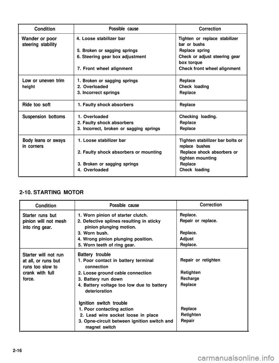
Condition
Wander or poor
steering stability
Low or uneven trim
height
Ride too soft
Suspension bottoms
Body leans or sways
in corners
Possible cause
4. Loose stabilizer bar
5. Broken or sagging springs
6. Steering gear box adjustment
7. Front wheel alignment
1. Broken or sagging springs
2. Overloaded
3. Incorrect springs
1. Faulty shock absorbers
1. Overloaded
2. Faulty shock absorbers
3. Incorrect, broken or sagging springs
1. Loose stabilizer bar
2. Faulty shock absorbers or mounting
3. Broken or sagging springs
4. Overloaded
Correction
Tighten or replace stabilizer
bar or bushs
Replace spring
Check or adjust steering gear
box torque
Check front wheel alignment
Replace
Check loading
Replace
Replace
Checking loading.
Replace
Replace
Tighten stabilizer bar bolts or
replace bushes
Replace shock absorbers or
tighten mounting
Replace
Check loading
STARTING MOTOR
Condition
Starter runs but
pinion will not mesh
into ring gear.
Starter will not run
at all, or runs but
runs too slow to
crank with full
force.
Possible cause
1. Worn pinion of starter clutch.
2. Defective splines resulting in sticky
pinion plunging motion.
3. Worn bush.
4. Wrong pinion plunging position.
5. Worn teeth of ring gear.
Battery trouble
1, Poor contact in battery terminal
connection
2. Loose ground cable connection
3. Battery run down
4. Battery voltage too low due to battery
deterioration
Correction
Replace.
Repair or replace.
Replace.
Adjust
Replace.
Repair or retighten
Retighten
Recharge
Replace
Ignition switch trouble
1. Poor contacting actionReplace
2. Lead wire socket loose in placeRetighten
3. Opne-circuit between ignition switch andRepair
magnet switch
2-10.
2-16
Page 333 of 962
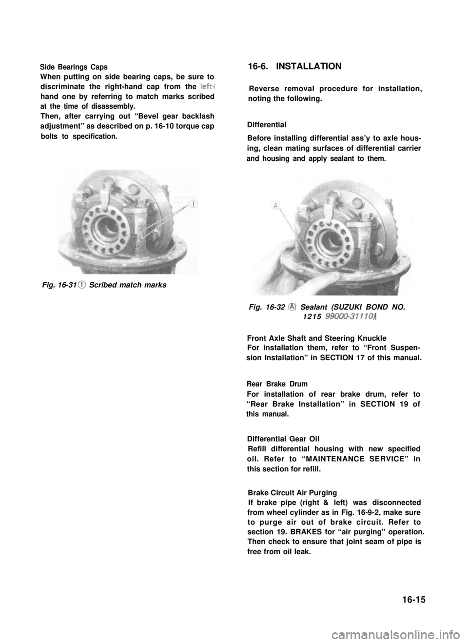
Side Bearings Caps
When putting on side bearing caps, be sure to
discriminate the right-hand cap from the left-
hand one by referring to match marks scribed
at the time of disassembly.
Then, after carrying out “Bevel gear backlash
adjustment” as described on p. 16-10 torque cap
bolts to specification.
16-6. INSTALLATION
Reverse removal procedure for installation,
noting the following.
Differential
Before installing differential ass’y to axle hous-
ing, clean mating surfaces of differential carrier
and housing and apply sealant to them.
Fig. 16-31 0 Scribed match marks
Fig. 16-32 @ Sealant (SUZUKI BOND NO.
1215 99000-31110)
Front Axle Shaft and Steering Knuckle
For installation them, refer to “Front Suspen-
sion Installation” in SECTION 17 of this manual.
Rear Brake Drum
For installation of rear brake drum, refer to
“Rear Brake Installation” in SECTION 19 of
this manual.
Differential Gear Oil
Refill differential housing with new specified
oil. Refer to “MAINTENANCE SERVICE” in
this section for refill.
Brake Circuit Air Purging
If brake pipe (right & left) was disconnected
from wheel cylinder as in Fig. 16-9-2, make sure
to purge air out of brake circuit. Refer to
section 19. BRAKES for “air purging" operation.
Then check to ensure that joint seam of pipe is
free from oil leak.
16-15
Page 356 of 962
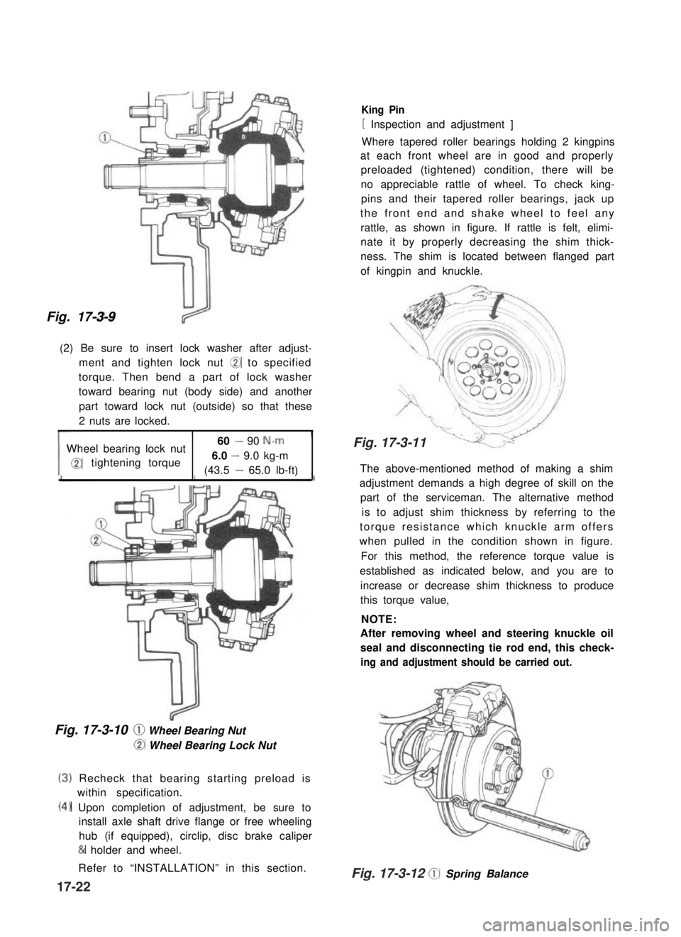
Fig. 17-3-9
(2) Be sure to insert lock washer after adjust-
ment and tighten lock nut @ to specified
torque. Then bend a part of lock washer
toward bearing nut (body side) and another
part toward lock nut (outside) so that these
2 nuts are locked.
Wheel bearing lock nut60 - 90 N-m
@tightening torque6.0 - 9.0 kg-m
(43.5 - 65.0 lb-ft)
Fig. 17-3-10 @ Wheel Bearing Nut
@ Wheel Bearing Lock Nut
(3)
(4)
Recheck that bearing starting preload is
within specification.
Upon completion of adjustment, be sure to
install axle shaft drive flange or free wheeling
hub (if equipped), circlip, disc brake caliper
& holder and wheel.
Refer to “INSTALLATION” in this section.
King Pin
[ Inspection and adjustment ]
Where tapered roller bearings holding 2 kingpins
at each front wheel are in good and properly
preloaded (tightened) condition, there will be
no appreciable rattle of wheel. To check king-
pins and their tapered roller bearings, jack up
the front end and shake wheel to feel any
rattle, as shown in figure. If rattle is felt, elimi-
nate it by properly decreasing the shim thick-
ness. The shim is located between flanged part
of kingpin and knuckle.
The above-mentioned method of making a shim
adjustment demands a high degree of skill on the
part of the serviceman. The alternative method
is to adjust shim thickness by referring to the
torque resistance which knuckle arm offers
when pulled in the condition shown in figure.
For this method, the reference torque value is
established as indicated below, and you are to
increase or decrease shim thickness to produce
this torque value,
NOTE:
After removing wheel and steering knuckle oil
seal and disconnecting tie rod end, this check-
ing and adjustment shouId be carried out.
@ Spring Balance
17-22
Fig. 17-3-12
Fig. 17-3-11
Page 371 of 962
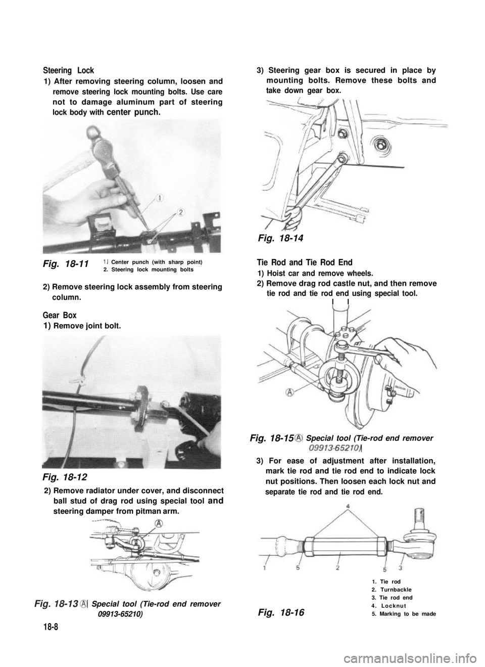
Steering Lock
1) After removing steering column, loosen and
remove steering lock mounting bolts. Use care
not to damage aluminum part of steering
lock body with center punch.
Fig. 18-11 1. Center punch (with sharp point)2. Steering lock mounting bolts
2) Remove steering lock assembly from steering
column.
Gear Box
1) Remove joint bolt.
Fig. 18-12
2) Remove radiator under cover, and disconnect
ball stud of drag rod using special tool and
steering damper from pitman arm.
-----‘CA2
@ Special tool (Tie-rod end remover
09913-65210)
18-8
3) Steering gear box is secured in place by
mounting bolts. Remove these bolts and
take down gear box.
Fig. 18-14
Tie Rod and Tie Rod End
1) Hoist car and remove wheels.
2) Remove drag rod castle nut, and then remove
tie rod and tie rod end using special tool.
I I
Fig. 18-15 @ Special tool (Tie-rod end remover
09913-65210)
3) For ease of adjustment after installation,
mark tie rod and tie rod end to indicate lock
nut positions. Then loosen each lock nut and
separate tie rod and tie rod end.
Fig. 18-16
1. Tie rod
2. Turnbackle
3. Tie rod end
4. Locknut
5. Marking to be made
Fig. 18-13
Page 372 of 962
![SUZUKI GRAND VITARA 1987 Service Repair Manual 18-5. INSPECTION OF COMPONENTS
Steering Gear Box
[Oil level]
Oil surface should be up to the level as shown
in below figures. If not, add prescribed gear oil,
SAE 90.
Right hand steering vehicle
Fig. SUZUKI GRAND VITARA 1987 Service Repair Manual 18-5. INSPECTION OF COMPONENTS
Steering Gear Box
[Oil level]
Oil surface should be up to the level as shown
in below figures. If not, add prescribed gear oil,
SAE 90.
Right hand steering vehicle
Fig.](/manual-img/20/57437/w960_57437-371.png)
18-5. INSPECTION OF COMPONENTS
Steering Gear Box
[Oil level]
Oil surface should be up to the level as shown
in below figures. If not, add prescribed gear oil,
SAE 90.
Right hand steering vehicle
Fig. 18-17
Left hand steering vehicle
I
35mm(1.4 in.)
Fig. 18-18
[Adjustment of worm shaft starting torque]
The steering gear box is provided with adjust-
ing bolt @ which gives preload to sector shaft.
Fig. 18-19 (1)Adjusting bolt
Make an adjustment according to the following
procedure.
1) Check worm shaft to ensure that it is free
from thrust play.
2) Position pitman arm in parallel with worm
shaft as shown below.
(With pitman arm in this position, front
wheel is in straightforward state.)
Worm shaft
Fig. 18-20
Pitman arm
18-9
Page 379 of 962
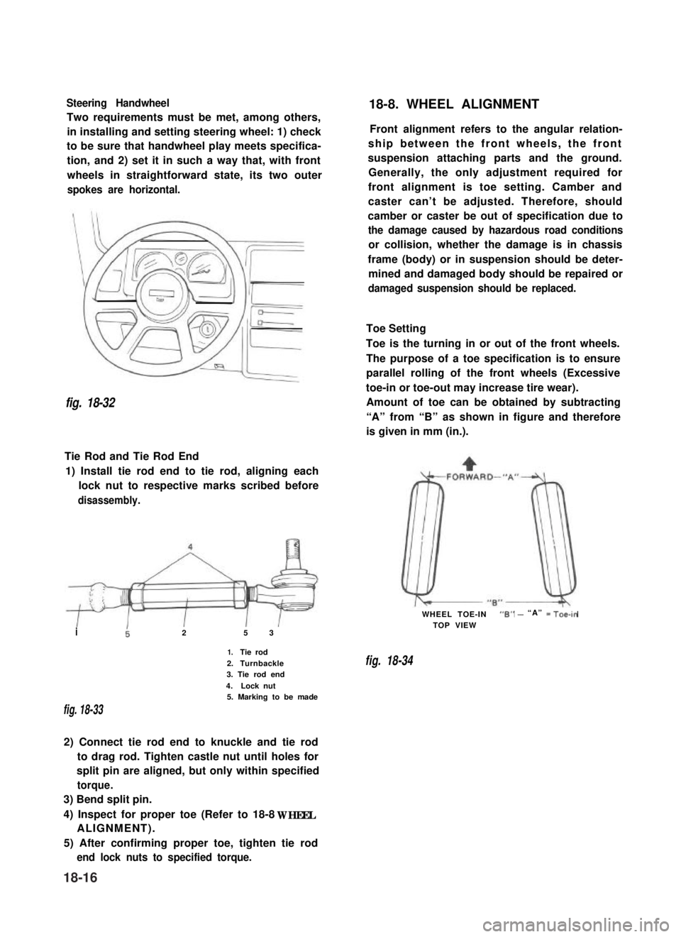
Steering Handwheel
Two requirements must be met, among others,
in installing and setting steering wheel: 1) check
to be sure that handwheel play meets specifica-
tion, and 2) set it in such a way that, with front
wheels in straightforward state, its two outer
spokes are horizontal.
fig. 18-32
Tie Rod and Tie Rod End
1) Install tie rod end to tie rod, aligning each
lock nut to respective marks scribed before
disassembly.
i25 3
1.Tie rod
2.Turnbackle3. Tie rod end
4.Lock nut5. Marking to be made
fig. 18-33
2) Connect tie rod end to knuckle and tie rod
to drag rod. Tighten castle nut until holes for
split pin are aligned, but only within specified
torque.
3) Bend split pin.
4) Inspect for proper toe (Refer to 18-8 WHEEL
ALIGNMENT).
5) After confirming proper toe, tighten tie rod
end lock nuts to specified torque.
18-8. WHEEL ALIGNMENT
Front alignment refers to the angular relation-
ship between the front wheels, the front
suspension attaching parts and the ground.
Generally, the only adjustment required for
front alignment is toe setting. Camber and
caster can’t be adjusted. Therefore, should
camber or caster be out of specification due to
the damage caused by hazardous road conditions
or collision, whether the damage is in chassis
frame (body) or in suspension should be deter-
mined and damaged body should be repaired or
damaged suspension should be replaced.
Toe Setting
Toe is the turning in or out of the front wheels.
The purpose of a toe specification is to ensure
parallel rolling of the front wheels (Excessive
toe-in or toe-out may increase tire wear).
Amount of toe can be obtained by subtracting
“A” from “B” as shown in figure and therefore
is given in mm (in.).
WHEEL TOE-IN“6” - “A” = Toe-in
TOP VIEW
fig. 18-34
18-16