1987 SUZUKI GRAND VITARA seats
[x] Cancel search: seatsPage 4 of 962
O-2. STANDARD SHOP PRACTICES
1. Protect painted surfaces of the body, and
avoid staining or tearing seats. When working
on fenders and seats, be sure to cover them
up with sheets.
2. Disconnect negative terminal connection of
the battery when working on any electrical
part or component. This is necessary for
avoiding electrical shocks and short-circuit-
ing, and is very simple to accomplish: merely
loosen wing nut on negative terminal and
separate cable from terminal post.
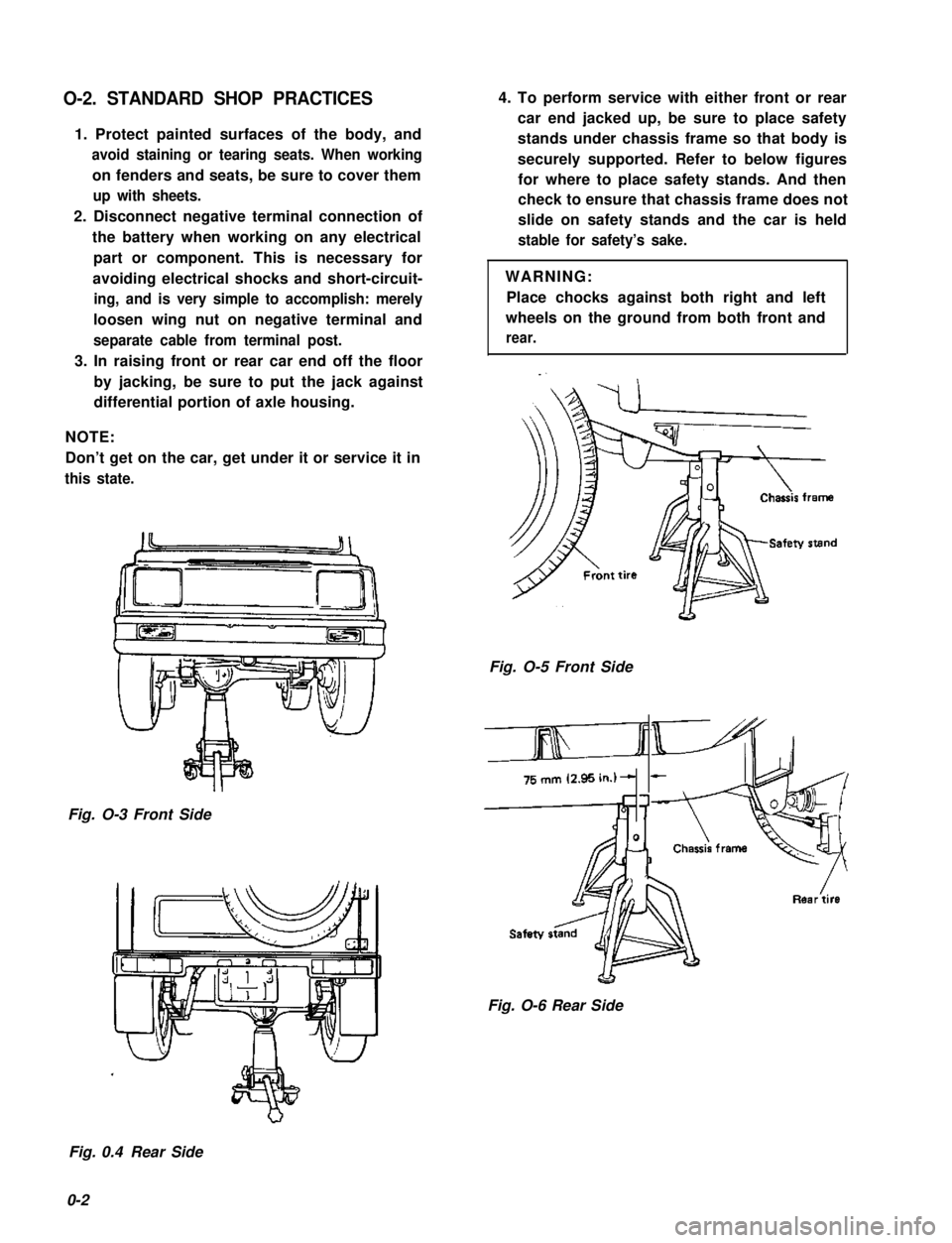
3. In raising front or rear car end off the floor
by jacking, be sure to put the jack against
differential portion of axle housing.
NOTE:
Don’t get on the car, get under it or service it in
this state.
Fig. O-3 Front Side
4. To perform service with either front or rear
car end jacked up, be sure to place safety
stands under chassis frame so that body is
securely supported. Refer to below figures
for where to place safety stands. And then
check to ensure that chassis frame does not
slide on safety stands and the car is held
stable for safety’s sake.
WARNING:
Place chocks against both right and left
wheels on the ground from both front and
rear.
Fig. O-5 Front Side
&
Fig. O-6 Rear Side
Fig. 0.4 Rear Side
0-2
Page 53 of 962

ConditionPossible causeCorrection
Rapid wear or uneven5. Wheel tires improperly “rotated“ toAdjust
wear of wheel tiresresult in unbalance
(Abnormal or excessive6. Disturbed front wheel alignmentAdjust as prescribed
tire wear)7. Hard drivingReplace tire
Steering noise1. Loose bolts and nuts
2. Loose leaf spring seats
3. Broken or otherwise damaged wheel
bearings
4. Worn or sticky tie rod ends
5. Linkage joints needling grease
Retighten
Retighten
Replace
Replace
Lubricate or replace
Too much play in
steering
1. Worn wheel bearings .Replace wheel bearing
2. Steering gear box attachments looseTighten or repair
3. Steering gear box adjustmentsCheck and adjust
4. Worn steering shaft jointsReplace joint
5. Worn tie rod ends or drug rod ball jointsReplace tie rod end or tie rod
Poor returnability1. Bind in tie rod end ball studs
2. Bind in steering column
3. Lack of lubricant steering gear box
4. Disturbed front end alignment
5. Steering gear box adjustment
6. Tires not adequatley inflated
Replace tie rod end
Repair or replace
Check, lubricate or replace
Check and adjust front end
alignment
Check and adjust gear box
torque
Adjust pressure
Abnormal noise,
front end
1. Worn, sticky or loose tie rod ends, drug
rod ball joints or axle shaft joints
2. Damaged shock absorbers or mountings
3. Loose stabilizer bar
4. Loose wheel nuts
5. Loose suspension bolts or nuts
6. Broken or otherwise damaged wheel
bearings
7. Broken suspension springs
Replace tie rod ends, drug
rod or axle shaft joints
Replace or repair
Tighten bolts or replace bushe!
Tighten
Tighten suspension bolts or
nuts
Replace
Replace
Wander or poor
steering stability
1. Mismatched or uneven tires
2. Loose tie rod ends or drug rod
3. Faulty shock absorber or mounting
Replace tire or inflate tires to
proper pressure
Replace tie rod end or drug ro(
Replace absorber or repair
mounting
2-15
Page 74 of 962
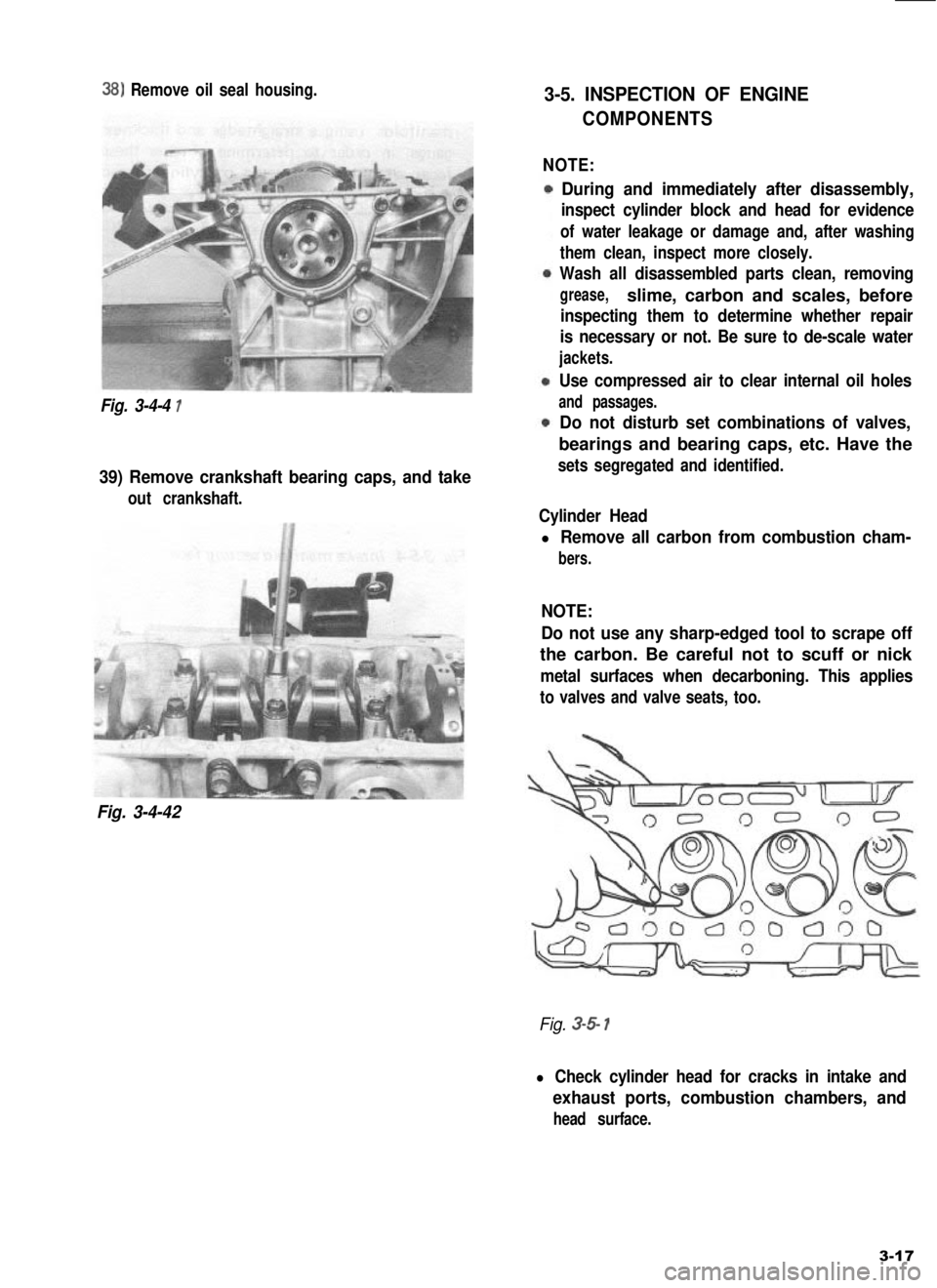
38) Remove oil seal housing.
Fig. 3-4-4 1
39) Remove crankshaft bearing caps, and take
out crankshaft.
Fig. 3-4-42
3-5. INSPECTION OF ENGINE
COMPONENTS
NOTE:
During and immediately after disassembly,
inspect cylinder block and head for evidence
of water leakage or damage and, after washing
them clean, inspect more closely.
Wash all disassembled parts clean, removing
grease,slime, carbon and scales, before
inspecting them to determine whether repair
is necessary or not. Be sure to de-scale water
jackets.
Use compressed air to clear internal oil holes
and passages.
Do not disturb set combinations of valves,
bearings and bearing caps, etc. Have the
sets segregated and identified.
Cylinder Head
l Remove all carbon from combustion cham-
bers.
NOTE:
Do not use any sharp-edged tool to scrape off
the carbon. Be careful not to scuff or nick
metal surfaces when decarboning. This applies
to valves and valve seats, too.
Fig. 3-5 1
l Check cylinder head for cracks in intake and
exhaust ports, combustion chambers, and
head surface.
3-17
Page 78 of 962
l Check end face of each valve stem for wear.
This face meets rocker arm intermittently
‘in operation, and might become concaved or
otherwise irregular. As necessary, smoothen
the end face with an oil stone and, if this
grinding removes the end stock by as much as
0.5 mm (0.0196 in.) (as measured from the
original face), replace the valve.
Limit on stock allowance0.5 mm
of valve stem end face(0.0196 in.)
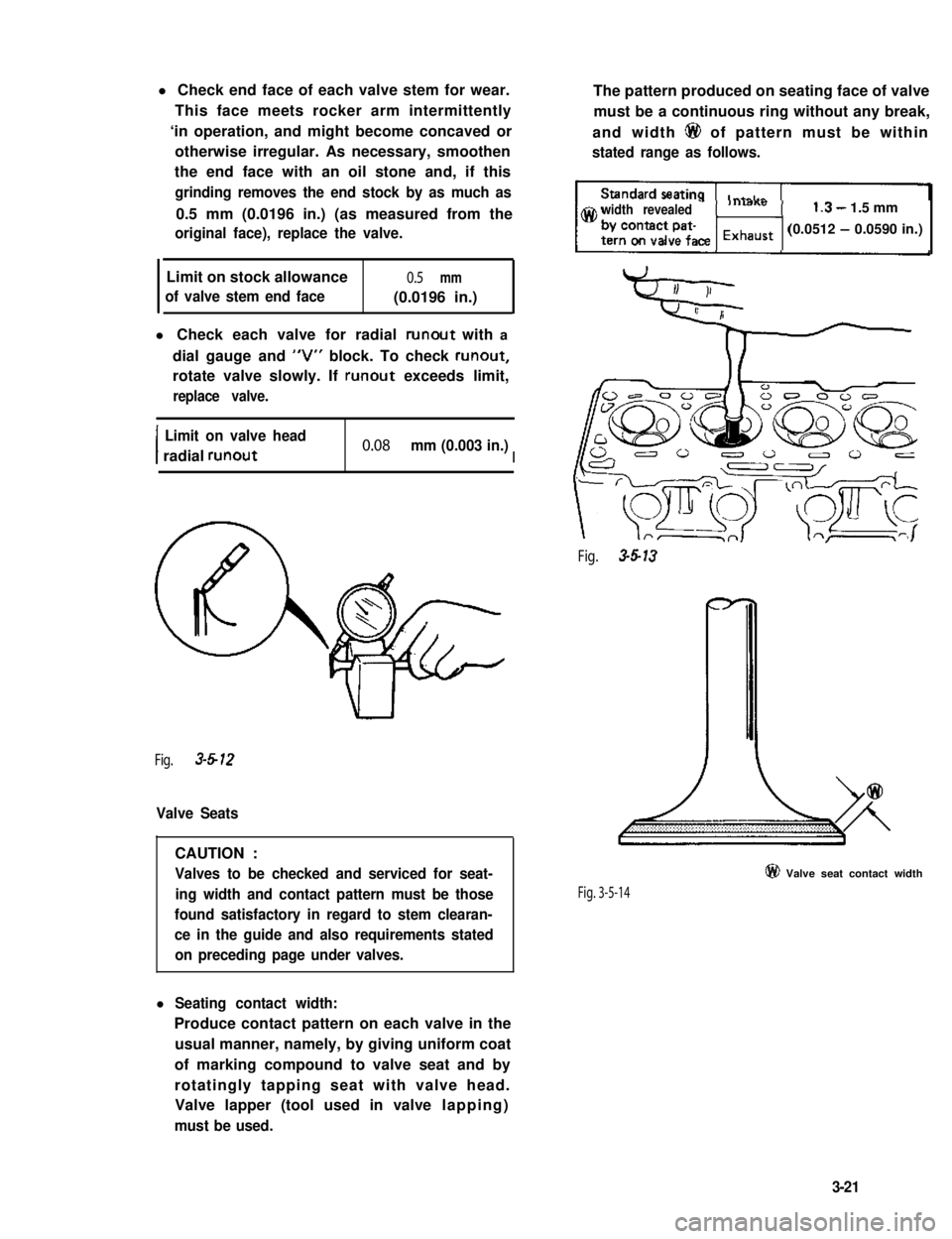
l Check each valve for radial runout with a
dial gauge and “V” block. To check runout,
rotate valve slowly. If runout exceeds limit,
replace valve.
I
Limit on valve head
radial runout0.08 mm (0.003 in.)I
Fig. 3-612
Valve Seats
CAUTION :
Valves to be checked and serviced for seat-
ing width and contact pattern must be those
found satisfactory in regard to stem clearan-
ce in the guide and also requirements stated
on preceding page under valves.
l Seating contact width:
Produce contact pattern on each valve in the
usual manner, namely, by giving uniform coat
of marking compound to valve seat and by
rotatingly tapping seat with valve head.
Valve lapper (tool used in valve lapping)
must be used.
The pattern produced on seating face of valve
must be a continuous ring without any break,
and width 6@ of pattern must be within
stated range as follows.
width revealed1.3- 1.5 mm
(0.0512 - 0.0590 in.)
Fig. 3-5-13
Fig. 3-5-14
@ Valve seat contact width
3-21
Page 79 of 962
l Valve seat repair:
Valve seat not producing uniform contact
with its valve or showing width @ of seating
contact that is off the specified range must be
repaired by regrinding or by cutting and
regrinding and finished by lapping.
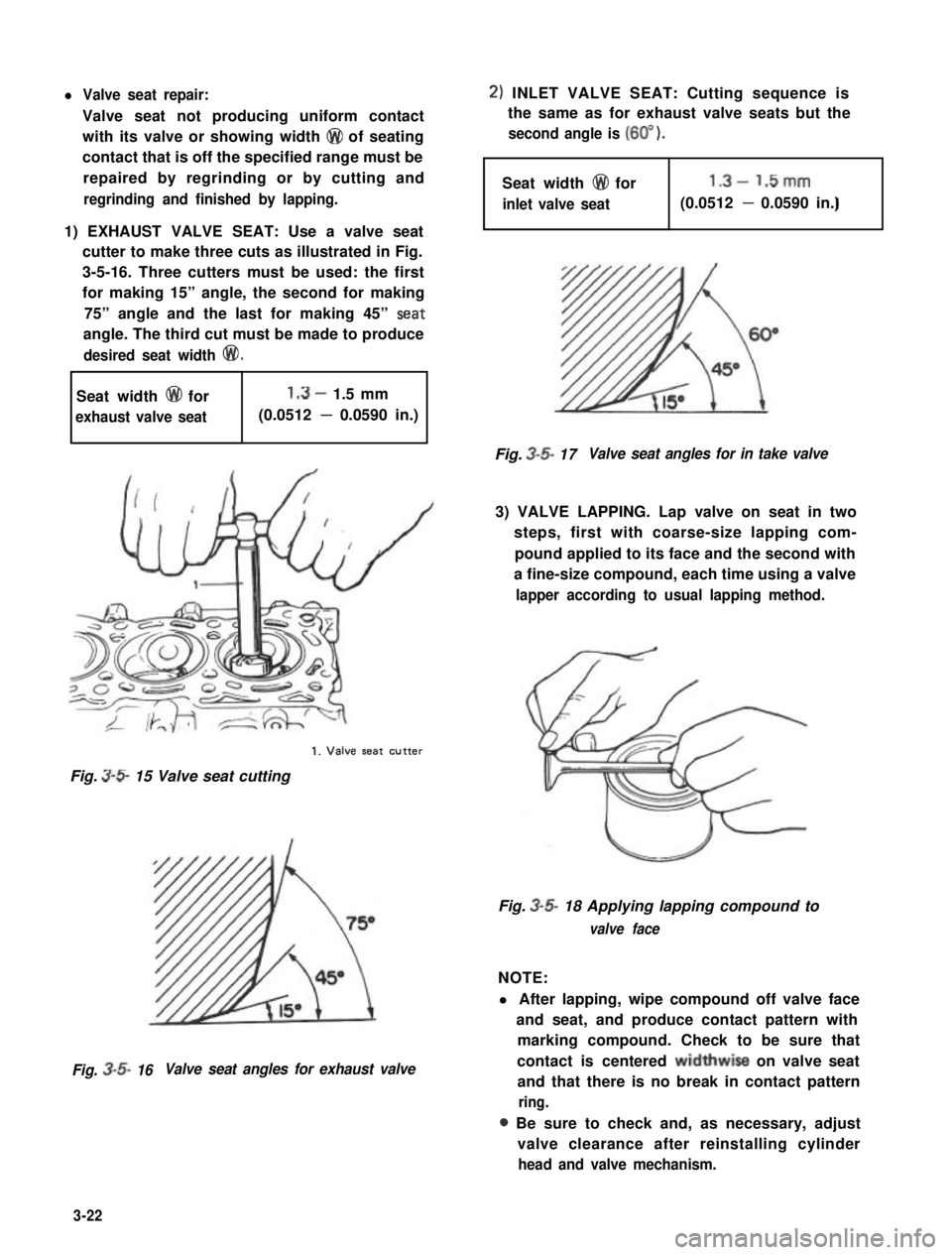
1) EXHAUST VALVE SEAT: Use a valve seat
cutter to make three cuts as illustrated in Fig.
3-5-16. Three cutters must be used: the first
for making 15” angle, the second for making
75” angle and the last for making 45” Seat
angle. The third cut must be made to produce
desired seat width @I!).
Seat width @ for1.3- 1.5 mm
exhaust valve seat(0.0512 - 0.0590 in.)
1. Valve seat CUtter
Fig. 3-S 15 Valve seat cutting
Fig. 3-5- 16Valve seat angles for exhaust valve
2) INLET VALVE SEAT: Cutting sequence is
the same as for exhaust valve seats but the
second angle is (60” ).
Seat width @I for1.3- 1.5mm
inlet valve seatI(0.0512 - 0.0590 in.)
Fig. 3-5- 17Valve seat angles for in take valve
3) VALVE LAPPING. Lap valve on seat in two
steps, first with coarse-size lapping com-
pound applied to its face and the second with
a fine-size compound, each time using a valve
lapper according to usual lapping method.
Fig. 3-5- 18 Applying lapping compound to
valve face
NOTE:
l After lapping, wipe compound off valve face
and seat, and produce contact pattern with
marking compound. Check to be sure that
contact is centered widthwise on valve seat
and that there is no break in contact pattern
ring.
a Be sure to check and, as necessary, adjust
valve clearance after reinstalling cylinder
head and valve mechanism.
3-22
Page 104 of 962
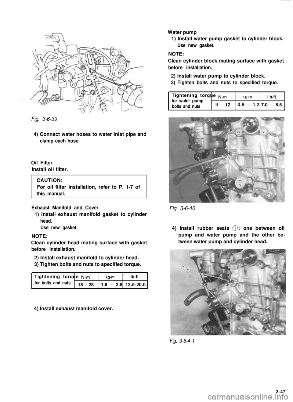
Fig. 3-6-39
4) Connect water hoses to water inlet pipe and
clamp each hose.
Oil FilterInstall oil filter.
CAUTION:For oil filter installation, refer to P. 1-7 of
this manual.
Exhaust Manifold and Cover
1) Install exhaust manifold gasket to cylinder
head. Use new gasket.
NOTE:
Clean cylinder head mating surface with gasket
before installation.
2) Install exhaust manifold to cylinder head.
3) Tighten bolts and nuts to specified torque.
Tightening torque
N.mkg-mlb-ft
for bolts and nuts18 - 28 1.8 - 2.8 13.5-20.0 Water pump
1) Install water pump gasket to cylinder block.
Use new gasket.
NOTE:
Clean cylinder block mating surface with gasket
before installation.
2) Install water pump to cylinder block.
3) Tighten bolts and nuts to specified torque.
Tightening torque N.m
for water pumpb-mI b-ft
bolts and nuts
8 - 12 0.9 - 1.2 7.0 - 8.5,
Fig. 3-6-40
4) Install rubber seats 0; one between oil
pump and water pump and the other be-
tween water pump and cylinder head.
4) Install exhaust manifold cover.
Fig. 3-6-4 1
3-47
Page 349 of 962
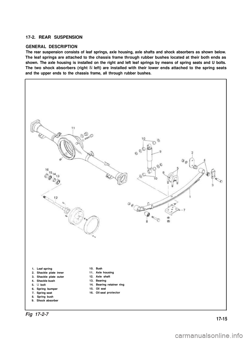
17-2. REAR SUSPENSION
GENERAL DESCRIPTION
The rear suspension consists of leaf springs, axle housing, axle shafts and shock absorbers as shown below.
The leaf springs are attached to the chassis frame through rubber bushes located at their both ends as
shown. The axle housing is installed on the right and left leaf springs by means of spring seats and U bolts.
The two shock absorbers (right & left) are installed with their lower ends attached to the spring seats
and the upper ends to the chassis frame, all through rubber bushes.
1. Leaf spring10.Bush
2.Shackle plate inner11.Axle housing
3.Shackle plate outer12.Axle shaft
4.Shackle bush13.Bearing
5.U bolt14.Bearing retainer ring
6.Spring bumper15.Oil seal
7.Spring seat16.Oil sealprotector
8. Spring bush9.Shock absorber
t-lg.
17-15
Fig 17-2-7
Page 384 of 962
/I
d-
Limitl.Mmm(0.047 in)
1.20 mm(0.047 in 1
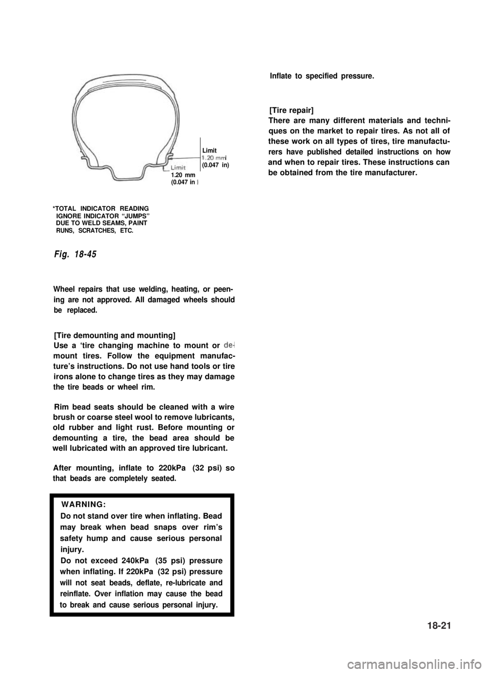
*TOTAL INDICATOR READINGIGNORE INDICATOR “JUMPS”DUE TO WELD SEAMS, PAINTRUNS, SCRATCHES, ETC.
Fig. 18-45
Wheel repairs that use welding, heating, or peen-
ing are not approved. All damaged wheels should
be replaced.
[Tire demounting and mounting]
Use a ‘tire changing machine to mount or de-
mount tires. Follow the equipment manufac-
ture’s instructions. Do not use hand tools or tire
irons alone to change tires as they may damage
the tire beads or wheel rim.
Rim bead seats should be cleaned with a wire
brush or coarse steel wool to remove lubricants,
old rubber and light rust. Before mounting or
demounting a tire, the bead area should be
well lubricated with an approved tire lubricant.
After mounting, inflate to 220kPa (32 psi) so
that beads are completely seated.
WARNING:
Do not stand over tire when inflating. Bead
may break when bead snaps over rim’s
safety hump and cause serious personal
injury.
Do not exceed 240kPa (35 psi) pressure
when inflating. If 220kPa (32 psi) pressure
will not seat beads, deflate, re-lubricate and
reinflate. Over inflation may cause the bead
to break and cause serious personal injury.1
Inflate to specified pressure.
[Tire repair]
There are many different materials and techni-
ques on the market to repair tires. As not all of
these work on all types of tires, tire manufactu-
rers have published detailed instructions on how
and when to repair tires. These instructions can
be obtained from the tire manufacturer.
18-21