1987 SUZUKI GRAND VITARA oil change
[x] Cancel search: oil changePage 5 of 962
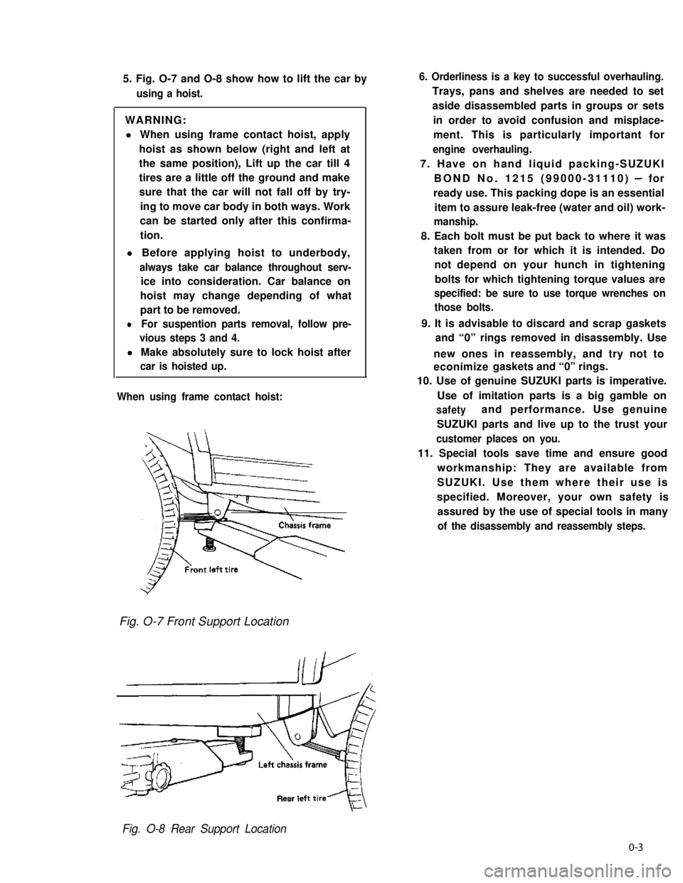
5. Fig. O-7 and O-8 show how to lift the car by
using a hoist.
WARNING:
l When using frame contact hoist, apply
hoist as shown below (right and left at
the same position), Lift up the car till 4
tires are a little off the ground and make
sure that the car will not fall off by try-
ing to move car body in both ways. Work
can be started only after this confirma-
tion.
l Before applying hoist to underbody,
always take car balance throughout serv-
ice into consideration. Car balance on
hoist may change depending of what
part to be removed.
lFor suspention parts removal, follow pre-
vious steps 3 and 4.
l Make absolutely sure to lock hoist after
car is hoisted up.
When using frame contact hoist:
6. Orderliness is a key to successful overhauling.
Trays, pans and shelves are needed to set
aside disassembled parts in groups or sets
in order to avoid confusion and misplace-
ment. This is particularly important for
engine overhauling.
7. Have on hand liquid packing-SUZUKI
BOND No. 1215 (99000-31110) - for
ready use. This packing dope is an essential
item to assure leak-free (water and oil) work-
manship.
8. Each bolt must be put back to where it was
taken from or for which it is intended. Do
not depend on your hunch in tightening
bolts for which tightening torque values are
specified: be sure to use torque wrenches on
those bolts.
9. It is advisable to discard and scrap gaskets
and “0” rings removed in disassembly. Use
new ones in reassembly, and try not to
econimize gaskets and “0” rings.
10. Use of genuine SUZUKI parts is imperative.
Use of imitation parts is a big gamble on
safetyand performance. Use genuine
SUZUKI parts and live up to the trust your
customer places on you.
11. Special tools save time and ensure good
workmanship: They are available from
SUZUKI. Use them where their use is
specified. Moreover, your own safety is
assured by the use of special tools in many
of the disassembly and reassembly steps.
Fig. O-7 Front Support Location
Fig. O-8 Rear Support Location
0-3
Page 20 of 962
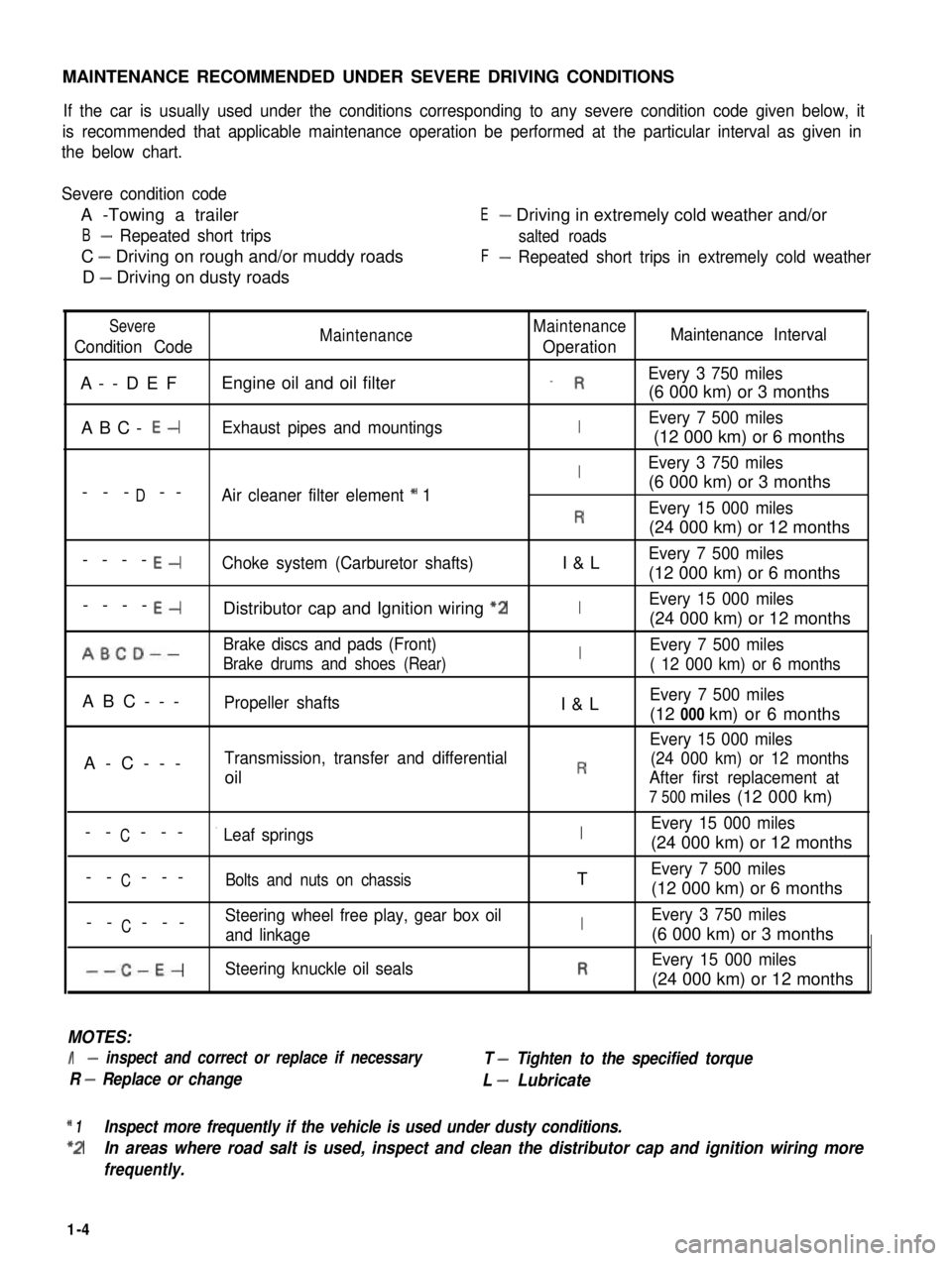
MAINTENANCE RECOMMENDED UNDER SEVERE DRIVING CONDITIONS
If the car is usually used under the conditions corresponding to any severe condition code given below, it
is recommended that applicable maintenance operation be performed at the particular interval as given in
the below chart.
Severe condition code
A -Towing a trailer
B- Repeated short trips
C - Driving on rough and/or muddy roads
D - Driving on dusty roads
E- Driving in extremely cold weather and/or
salted roads
F- Repeated short trips in extremely cold weather
Severe
Condition CodeMaintenanceMaintenance
OperationMaintenance Interval
A--DEFEngine oil and oil filter_ REvery 3 750 miles
(6 000 km) or 3 months
ABC- E-Exhaust pipes and mountingsIEvery 7 500 miles
(12 000 km) or 6 months
IEvery 3 750 miles
D(6 000 km) or 3 months--- --Air cleaner filter element * 1
REvery 15 000 miles
(24 000 km) or 12 months
----E-Choke system (Carburetor shafts)I&LEvery 7 500 miles
(12 000 km) or 6 months
----E-Distributor cap and Ignition wiring “2IEvery 15 000 miles
(24 000 km) or 12 months
ABCD--Brake discs and pads (Front)IEvery 7 500 miles
Brake drums and shoes (Rear)( 12 000 km) or 6 months
ABC---Propeller shaftsI&LEvery 7 500 miles
(12 000 km) or 6 months
Every 15 000 miles
A-C---Transmission, transfer and differential(24 000 km) or 12 months
oilRAfter first replacement at
7 500 miles (12 000 km)
CEvery 15 000 miles-- ---’ Leaf springsI(24 000 km) or 12 months
C-- ---Bolts and nuts on chassisTEvery 7 500 miles
(12 000 km) or 6 months
CSteering wheel free play, gear box oil-- ---and linkageIEvery 3 750 miles
(6 000 km) or 3 months
--C-E-Steering knuckle oil sealsREvery 15 000 miles
(24 000 km) or 12 months
MOTES:
I- inspect and correct or replace if necessary
R - Replace or change
T - Tighten to the specified torque
L - Lubricate
* 1Inspect more frequently if the vehicle is used under dusty conditions.
*2In areas where road salt is used, inspect and clean the distributor cap and ignition wiring more
frequently.
1-4
Page 23 of 962
NOTE:
Steps 1) - 6) outlined above must be performed
with ENGINE NOT RUNNING. For step 7),
be sure to have adequate ventilation while
engine is running
It is recommended to use engine oil of SE or
SF class.
NOTE:For temperatures below
32”F(O”C), it is highly
recommended to use SAE 5W-30 oil.
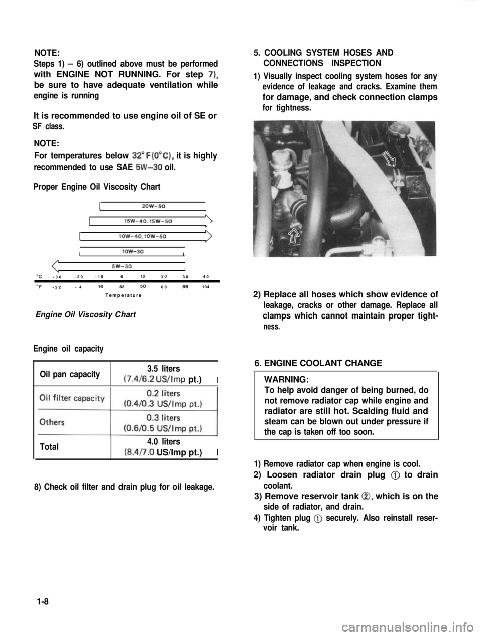
Proper Engine Oil Viscosity Chart
12OW-50
lSW-40.15w-501
Ilow-4O.lOW-50
Ilow-30I
5w-30I“C-3 0 -2
0 -1
0 0 102
0
30 4
0
OF-2 2 -
4 14
32506886104
Temperatur e
Engine Oil Viscosity Chart
Engine oil capacity
Oil pan capacity 3.5 liters (7.4/6.2
US/Imp pt.)I
Total 4.0 liters(8.4/7.0 US/Imp pt.)I
8) Check oil filter and drain plug for oil leakage.
5. COOLING SYSTEM HOSES AND
CONNECTIONS INSPECTION
1) Visually inspect cooling system hoses for any
evidence of leakage and cracks. Examine them
for damage, and check connection clamps
for tightness.
2) Replace all hoses which show evidence of
leakage, cracks or other damage. Replace all
clamps which cannot maintain proper tight-
ness.
6. ENGINE COOLANT CHANGE
WARNING:
To help avoid danger of being burned, do
not remove radiator cap while engine and
radiator are still hot. Scalding fluid and
steam can be blown out under pressure if
the cap is taken off too soon.
1) Remove radiator cap when engine is cool.
2) Loosen radiator drain plug @
to drain
coolant.
3) Remove reservoir tank 0, which is on the
side of radiator, and drain.
4) Tighten plug
@ securely. Also reinstall reser-
voir tank.
1-8
Page 24 of 962
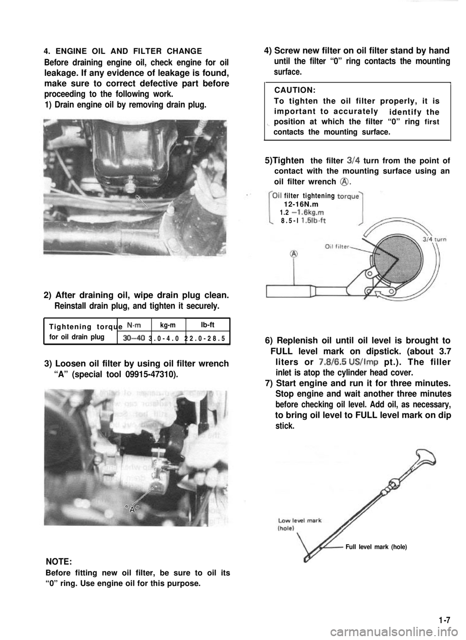
4. ENGINE OIL AND FILTER CHANGEBefore draining engine oil, check engine for oil
leakage. If any evidence of leakage is found,
make sure to correct defective part before
proceeding to the following work.
1) Drain engine oil by removing drain plug.
2) After draining oil, wipe drain plug clean.
Reinstall drain plug, and tighten it securely.
Tightening torque N-m kg-mlb-ft
for oil drain plug30-40 3.0-4.0 22.0-28.
5
3) Loosen oil filter by using oil filter wrench
“A” (special tool 09915-47310).
4) Screw new filter on oil filter stand by hand
until the filter “0” ring contacts the mounting
surface.
ICAUTION:
To tighten the oil filter properly, it is important to accurately identify the
1-position at which the filter “0” ring first
contacts the mounting surface.
5)Tighten the filter 3/4 turn from the point of
contact with the mounting surface using an
oil filter wrench
@.
filter tightening
12-16N.m
1.2
-1.6kg.m
8.5-l l.lilb-ft
6) Replenish oil until oil level is brought to
FULL level mark on dipstick. (about 3.7liters or 7.8/6.5
US/Imp pt.). The filler
inlet is atop the cylinder head cover.
7) Start engine and run it for three minutes.
Stop engine and wait another three minutes
before checking oil level. Add oil, as necessary,
to bring oil level to FULL level mark on dip
stick.
NOTE:
Before fitting new oil filter, be sure to oil its
“0” ring. Use engine oil for this purpose.
v
Full level mark (hole)
1-7
Page 36 of 962
3) Check propeller shaft (No. 1, No. 2, No. 3)
flange yoke bolts for tightness, and retighten
them as necessary:
N.mkg-mlb-ftTighteningtorque23-302.3-3.017.0-21.5
42. TRANSMISSION, TRANSFER,
DIFFERENTIAL OIL INSPECTION
AND CHANGE
[I nspectionl
1) Inspect transmission case, transfer case and
differential housing for evidence of oil leakage.
Repair leaky point if any.
2) Make sure that the car is placed level for oil
level check.
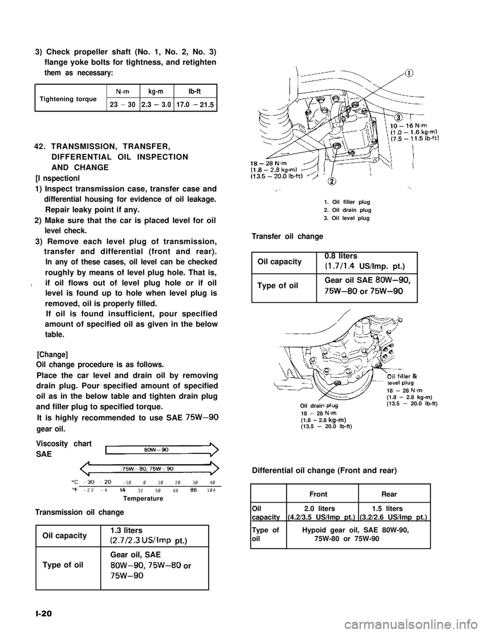
3) Remove each level plug of transmission,
transfer and differential (front and rear).
In any of these cases, oil level can be checked
roughly by means of level plug hole. That is,
,if oil flows out of level plug hole or if oil
level is found up to hole when level plug is
removed, oil is properly filled.
If oil is found insufficient, pour specified
amount of specified oil as given in the below
table.
[Change]
Oil change procedure is as follows.
Place the car level and drain oil by removing
drain plug. Pour specified amount of specified
oil as in the below table and tighten drain plug
and filler plug to specified torque.
It is highly recommended to use SAE 75W-90
gear oil.
Viscosity chart
SAE
75w-ao,75w-90
"C -30 --20 -10 0 10 20 30 40"F -22 -4lb 32 50 68 86104
Temperature
Transmission oil change
Oil capacity
Type of oil
1.3 liters
(2.7/2.3 US/Imp pt.)
Gear oil, SAE
8OW-90,75W-80 or
75w-90
l-20
18-28N.m
I ”’
1. Oil filler plug
2. Oil drain plug
3. Oil level plug
Transfer oil change
Oil capacity0.8 liters
(1.7/l .4 US/Imp. pt.)
Type of oilGear oil SAE 8OW-90,
75W-80 or 75W-90
18 - 28 N.m(1.8 - 2.8 kg-m)(13.5 - 20.0 lb-ft)-R-Oil drair18 - 28 N&(1.8 - 2.8 kg-m)(13.5 - 20.0 lb-ft)
Differential oil change (Front and rear)
1.5 liters
(3.2/2.6 US/Imp pt.)
2.0 liters
(4.2/3.5 US/Imp pt.)
FrontRear
Oil
capacity
Type of
oil
Hypoid gear oil, SAE 80W-90,
75W-80 or 75W-90
Page 45 of 962
9
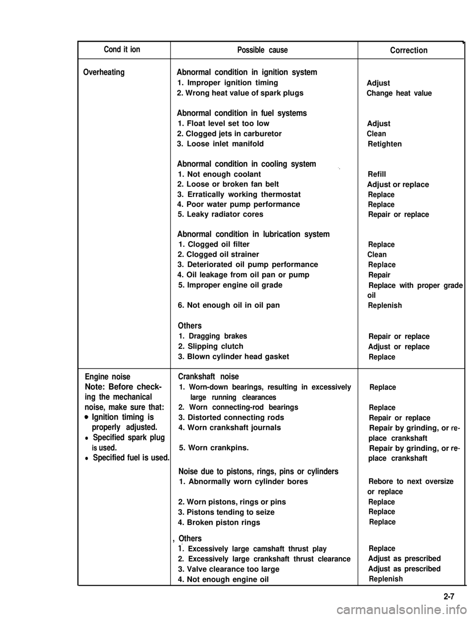
Cond it ionPossible causeCorrection
OverheatingAbnormal condition in ignition system
1. Improper ignition timingAdjust
2. Wrong heat value of spark plugsChange heat value
Abnormal condition in fuel systems
1. Float level set too lowAdjust
2. Clogged jets in carburetorClean
3. Loose inlet manifoldRetighten
Abnormal condition in cooling system,,
1. Not enough coolantRefill
2. Loose or broken fan beltAdjust or replace
3. Erratically working thermostatReplace
4. Poor water pump performanceReplace
5. Leaky radiator coresRepair or replace
Abnormal condition in lubrication system
1. Clogged oil filterReplace
2. Clogged oil strainerClean
3. Deteriorated oil pump performanceReplace
4. Oil leakage from oil pan or pumpRepair
5. Improper engine oil gradeReplace with proper grade
oil
6. Not enough oil in oil panReplenish
Others
1. Dragging brakesRepair or replace
2. Slipping clutchAdjust or replace
3. Blown cylinder head gasketReplace
Engine noiseCrankshaft noise
Note: Before check- 1. Worn-down bearings, resulting in excessivelyReplace
ing the mechanicallarge running clearances
noise, make sure that:2. Worn connecting-rod bearingsReplace
0 Ignition timing is3. Distorted connecting rodsRepair or replace
properly adjusted.4. Worn crankshaft journalsRepair by grinding, or re-
l Specified spark plugplace crankshaft
is used.5. Worn crankpins.Repair by grinding, or re-
l Specified fuel is used.place crankshaft
Noise due to pistons, rings, pins or cylinders
1. Abnormally worn cylinder boresRebore to next oversize
or replace
2. Worn pistons, rings or pinsReplace
3. Pistons tending to seizeReplace
4. Broken piston ringsReplace
, Others
1’. Excessively large camshaft thrust playReplace
2. Excessively large crankshaft thrust clearanceAdjust as prescribed
3. Valve clearance too largeAdjust as prescribed
4. Not enough engine oilReplenish
2-7
Page 49 of 962

Condition
Excessive gear noise
Hard shifting
2-6. DIFFERENTIALS
Possible cause
1. Not enough oil in transmission
2. Defective synchronizer
3. Gears rattling in thrust direction
4. Broken or worn bearings
5. Damaged or worn gears
1. Clutch pedal play too large, resulting in a
“dragging clutch”
2. Worn clutch disc facings
3. Clutch disc facings dirty with oil.
4. Distorted or unevenly worn shift fork shaft
5. Broken locating balls
6. Worn synchornizer sleeve or ring
7. Worn synchronizer hub
Condition
Gear noise
Bearing noise
Possible cause
1. Maladjusted backlash between drive pinion
and ring gear
2. Damaged gear teeth or improper mesh of
drive pinion and ring gear
3. Improper tooth contact in the mesh between
drive pinion and ring gear
4. Insufficient or wrong kind of gear oil
5. Ring gear wobbling when turning, or ring
gear securing bolts loose
6. Broken or otherwise damaged teeth of side
gears or differential pinion gears
1. (Constant noise) Insufficient or wrong kind
of gear oil
2. (Constant noise) Damaged or worn bearings
or borne parts
3. (Noise during coasting) Damaged bearings
of rear drive pinion
4. (Noise during turning) Broken bearings
on axle shafts
Correction
Replenish
Replace
Replace
Replace
Replace
Adjust as prescribed
Replace.
Replace.
Replace
Replace
Replace
Replace
Correction
Adjust as prescribed
Replace or adjust
Adjust as prescribed
Replenish or replace
Replace, or retighten
Replace
Replenish or change
Replace.
Replace
Replace
2-11
Page 61 of 962
3) Cylinder Head and Valve Train
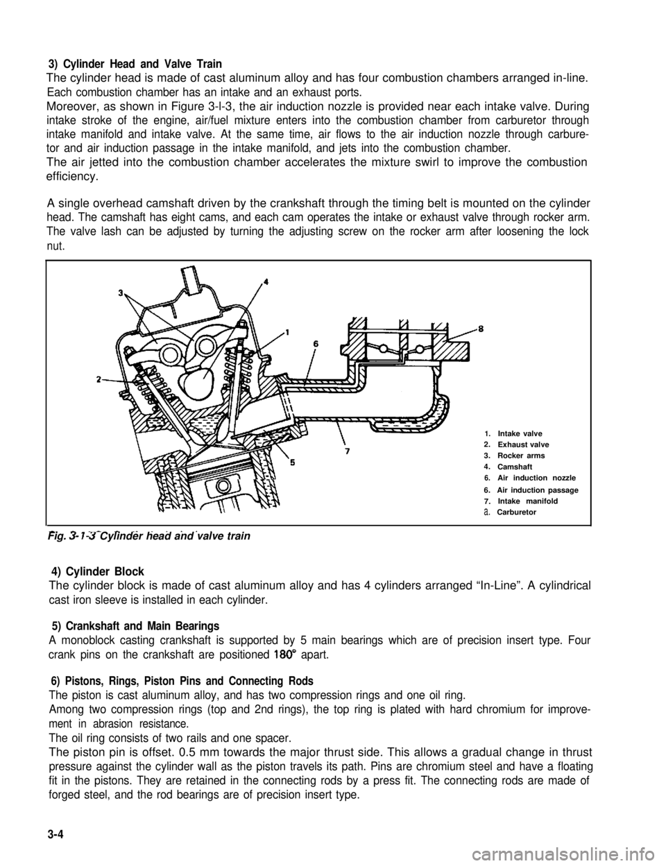
The cylinder head is made of cast aluminum alloy and has four combustion chambers arranged in-line.
Each combustion chamber has an intake and an exhaust ports.
Moreover, as shown in Figure 3-l-3, the air induction nozzle is provided near each intake valve. During
intake stroke of the engine, air/fuel mixture enters into the combustion chamber from carburetor through
intake manifold and intake valve. At the same time, air flows to the air induction nozzle through carbure-
tor and air induction passage in the intake manifold, and jets into the combustion chamber.
The air jetted into the combustion chamber accelerates the mixture swirl to improve the combustion
efficiency.
A single overhead camshaft driven by the crankshaft through the timing belt is mounted on the cylinder
head. The camshaft has eight cams, and each cam operates the intake or exhaust valve through rocker arm.
The valve lash can be adjusted by turning the adjusting screw on the rocker arm after loosening the lock
nut.
2-
1.Intake valve2.Exhaust valve
3.Rocker arms
4.Camshaft
6.Air induction nozzle
6.Air induction passage
7.Intake manifold
a.Carburetor
-. - _- - ._ . . . . .Fig. 3- 7-3 Cylinder head and valve train
4) Cylinder Block
The cylinder block is made of cast aluminum alloy and has 4 cylinders arranged “In-Line”. A cylindrical
cast iron sleeve is installed in each cylinder.
5) Crankshaft and Main Bearings
A monoblock casting crankshaft is supported by 5 main bearings which are of precision insert type. Four
crank pins on the crankshaft are positioned 180” apart.
6) Pistons, Rings, Piston Pins and Connecting Rods
The piston is cast aluminum alloy, and has two compression rings and one oil ring.
Among two compression rings (top and 2nd rings), the top ring is plated with hard chromium for improve-
ment in abrasion resistance.
The oil ring consists of two rails and one spacer.
The piston pin is offset. 0.5 mm towards the major thrust side. This allows a gradual change in thrust
pressure against the cylinder wall as the piston travels its path. Pins are chromium steel and have a floating
fit in the pistons. They are retained in the connecting rods by a press fit. The connecting rods are made of
forged steel, and the rod bearings are of precision insert type.
3-4