1987 SUZUKI GRAND VITARA oil change
[x] Cancel search: oil changePage 112 of 962
Engine Coolant
This subject is covered in SECTION 6 ENGINE
COOLING SYSTEM.
Exhaust Line and Muffler
Inspect each exhaust line connection for tight-
ness, and examine muffler and other parts for
evidence of breakage and leakage of gases.
Repair or replace defective parts, if any.
Compression Pressure Measurement
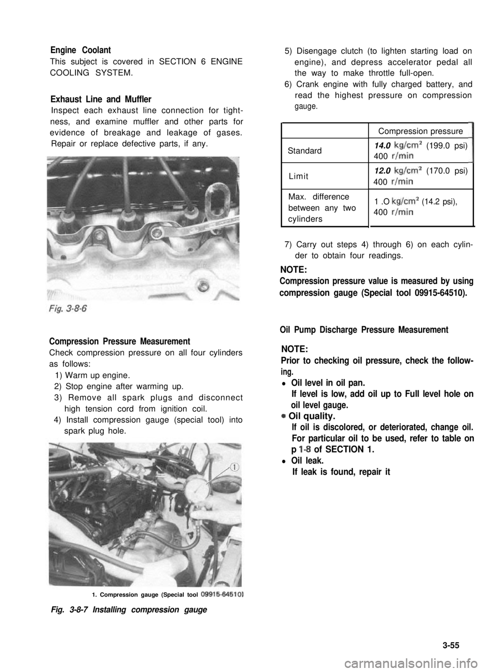
Check compression pressure on all four cylinders
as follows:
1) Warm up engine.
2) Stop engine after warming up.
3) Remove all spark plugs and disconnect
high tension cord from ignition coil.
4) Install compression gauge (special tool) into
spark plug hole.
5) Disengage clutch (to lighten starting load on
engine), and depress accelerator pedal all
the way to make throttle full-open.
6) Crank engine with fully charged battery, and
read the highest pressure on compression
gauge.
Standard
Limit
Max. difference
between any two
cylinders
Compression pressure
14.0 kg/cm2 (199.0 psi)
400 r/min
12.0 kg/cm2 (170.0 psi)
400 r/min
1 .O kg/cm2 (14.2 psi),
400 r/min
3
7) Carry out steps 4) through 6) on each cylin-
der to obtain four readings.
NOTE:
Compression pressure value is measured by using
compression gauge (Special tool 09915-64510).
Oil Pump Discharge Pressure Measurement
NOTE:
Prior to checking oil pressure, check the follow-
ing.
l Oil level in oil pan.
If level is low, add oil up to Full level hole on
oil level gauge.
0 Oil quality.
If oil is discolored, or deteriorated, change oil.
For particular oil to be used, refer to table on
p l-8 of SECTION 1.
l Oil leak.
If leak is found, repair it
1. Compression gauge (Special tool 09915-64510)
Fig. 3-8-7 Installing compression gauge
3-55
Page 212 of 962
8-l. GENERAL DESCRIPTION
The ignition system is of contact-pointless type (full-transistorized type).
The principal components of the ignition system are spark plugs, ignition coil, and distributor. The distri-
butor has a rotor, an ignitor, a signal generator, a vacuum advancer and a centrifugal advancer.
The signal generator is to generate the ignition signal and consists of a signal rotor, a magnet and a pickup
coil. The signal rotor is attached to the distributor shaft, and the magnet and the pickup coil are attached
to the generator base plate.
When the distributor shaft rotates, the magnetic flux passing through the pickup coil varies due to the
change in air gap between the pickup coil and the signal rotor. As a result, the alternating current voltage
is induced in the pickup coil. The voltage induced turns on and off the ignitor which switches off the
ignition coil primary current. Thus, the high voltage is induced in the secondary winding of ignition coil
and ignition sparks are generated at the spark plugs.
The distributor is a sort of rotary switch, whose rotor connects the four plugs, one at a time, to secondary
winding of the ignition coil through the wires called “high-tension” cords. Note that there are one high-
tension cord, from secondary winding to the center of the distributor cap, and four more high-tension
cords between the spark plugs and the four terminals on the cap.
NOTE:
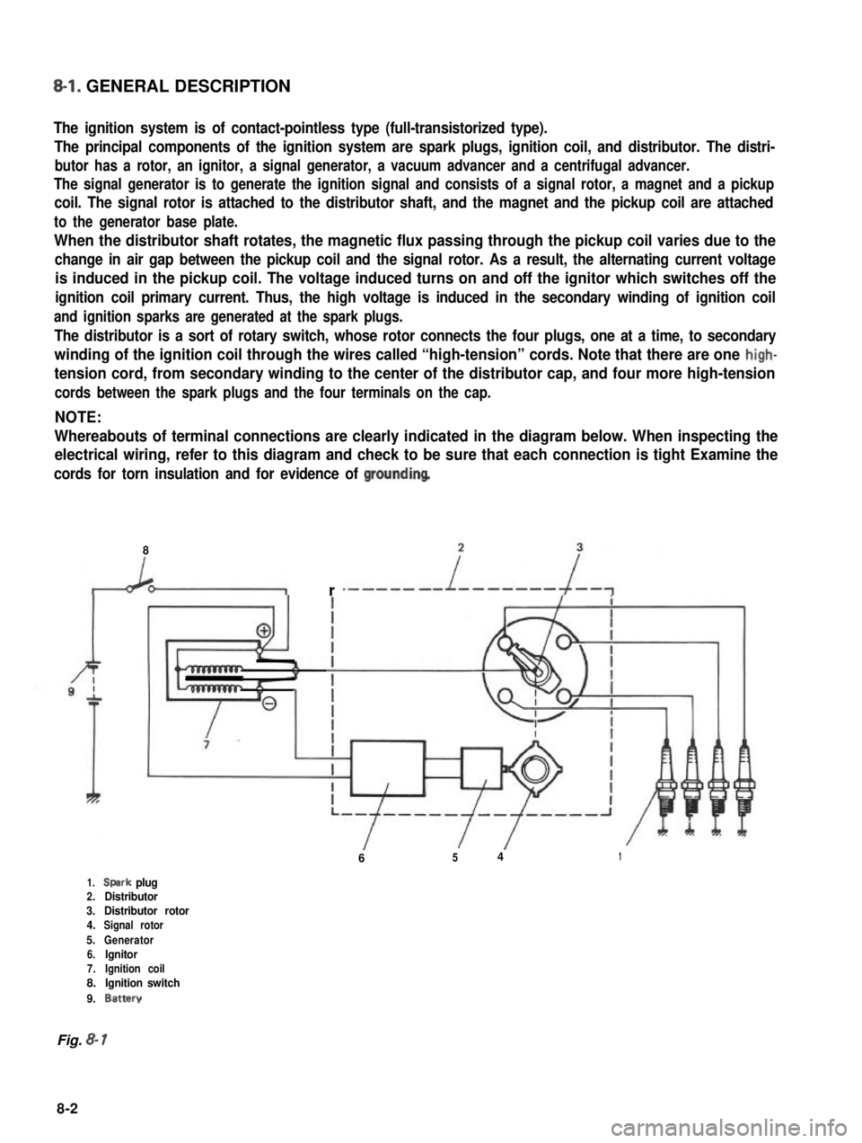
Whereabouts of terminal connections are clearly indicated in the diagram below. When inspecting the
electrical wiring, refer to this diagram and check to be sure that each connection is tight Examine the
cords for torn insulation and for evidence of groundinq
8
r
6541
1.Spark plug2.Distributor3.Distributor rotor4.Signal rotor
5.Generator6.lgnitor7.Ignition coil8.Ignition switch
9.Battery
Fig. 8- 1
8-2
Page 214 of 962
Ignition Coil
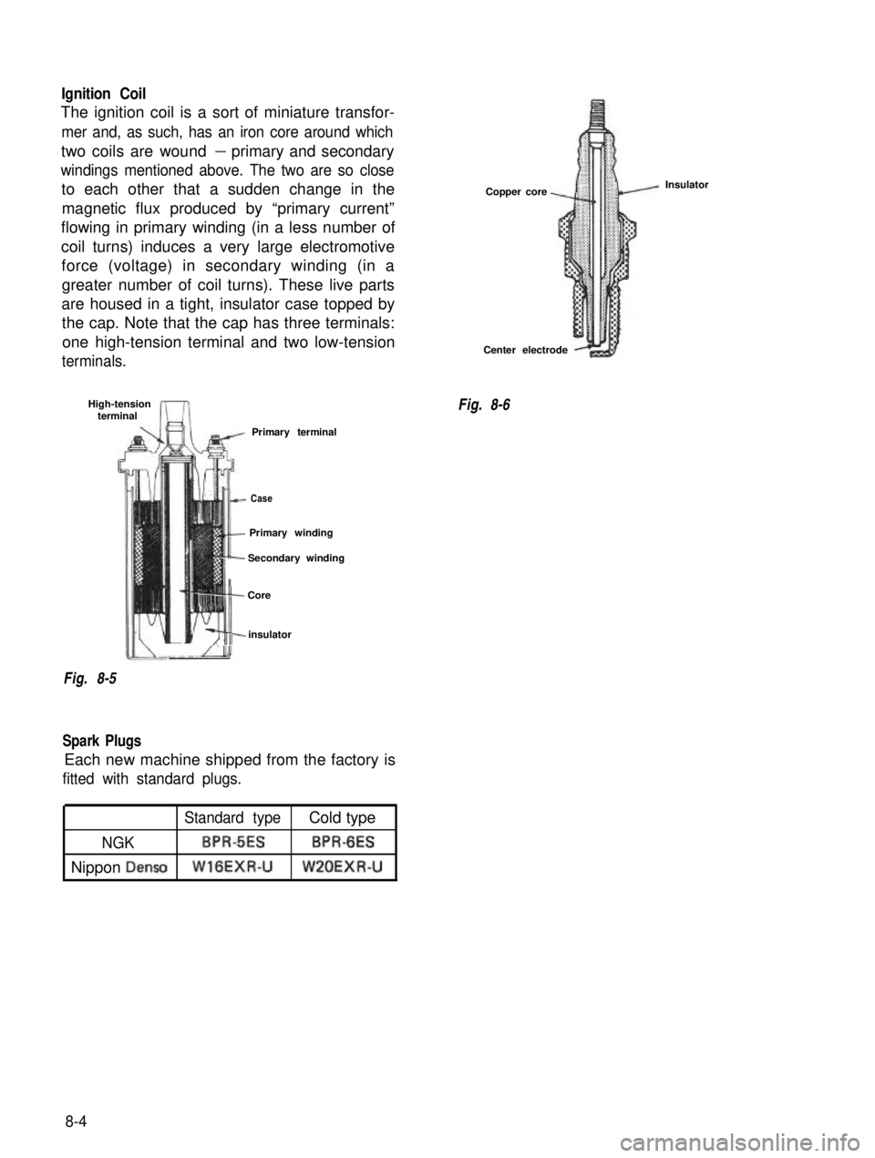
The ignition coil is a sort of miniature transfor-
mer and, as such, has an iron core around which
two coils are wound- primary and secondary
windings mentioned above. The two are so close
to each other that a sudden change in themagnetic flux produced by “primary current”
flowing in primary winding (in a less number of
coil turns) induces a very large electromotive force (voltage) in secondary winding (in a
greater number of coil turns). These live parts
are housed in a tight, insulator case topped by the cap. Note that the cap has three terminals:
one high-tension terminal and two low-tension
terminals.
High-tension terminal
Primary terminal
lt-
Case
It
Primary winding
II
Secondary winding
j- Core
m2 I,,,insulator
Fig. 8-5
Spark Plugs
Each new machine shipped from the factory is
fitted with standard plugs.
Copper core
Center electrode
Fig. 8-6 Insulator
Standard typeCold type
NGKBPRdESBPR-6ES
Nippon DensoWlGEXR-UW’LOEXR-U
8-4
Page 236 of 962
The alternator features a solid state regulator
that is mounted inside the alternator. All regula-
tor components are enclosed into a solid mold,
and this unit along with the brush holder assemb-
ly is attached to the slip ring end frame. The
regulator voltage setting cannot be adjusted.
The alternator rotor bearings contain enough
grease to eliminate the need for periodic lubri-
cation. Two brushes carry current through the
two slip rings to the field coil mounted on the
rotor, and under normal conditions will provide
long period of attention-free service.
The stator windings are assembled on the inside
of a laminated core that forms part of the
alternator frame. A rectifier bridge connected
to the stator windings contains six diodes,
and electrically changes the stator A.C. voltages
to a D.C. voltage which appears at the generator
output terminal.
The neutral diodes serve to convert the voltage
fluctuation at the neutral point to direct current
for increasing the alternator output.
A condenser mounted in the end frame protects
the diodes from high voltages and suppresses
radio noise.
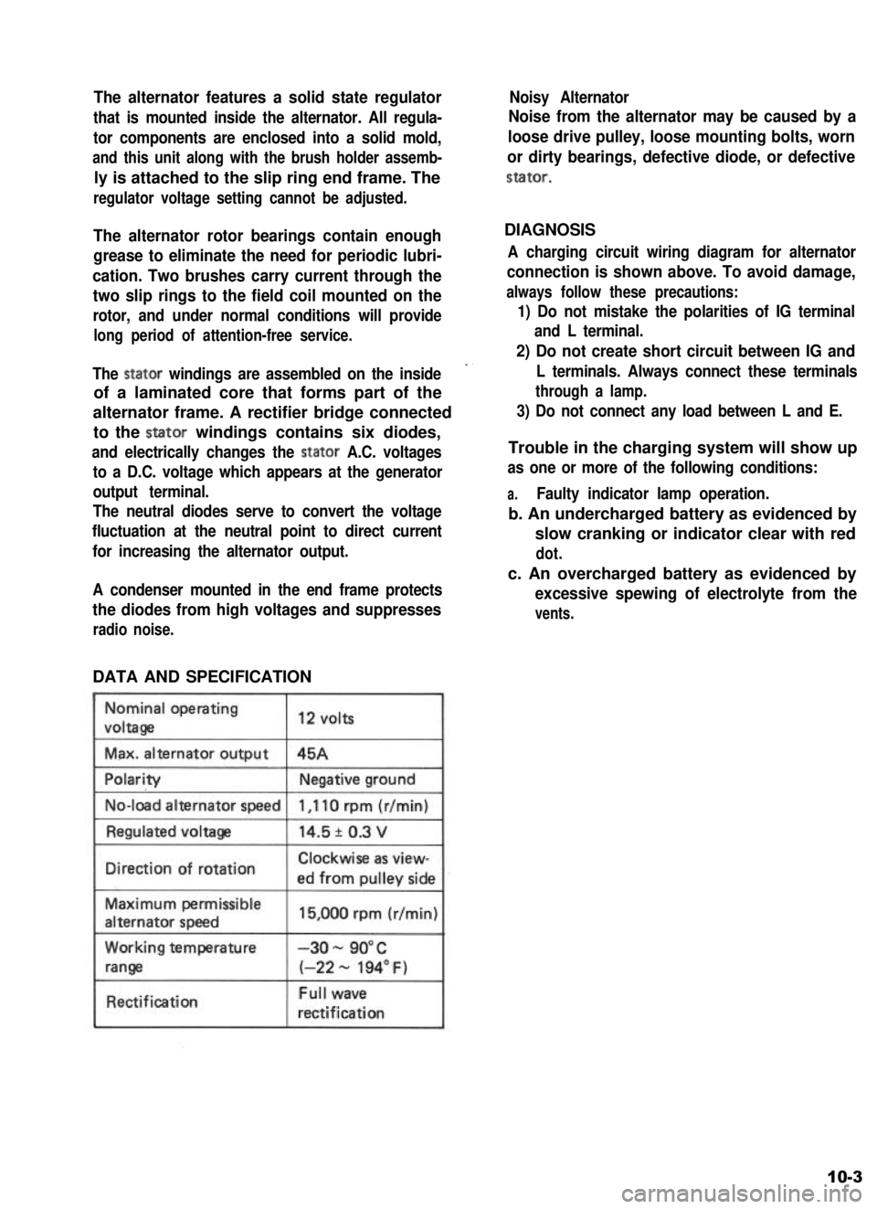
DATA AND SPECIFICATION
Nominal operating
voltaga
Max. alternator output
12 volts
45A
No-load alternator speed
IDirection of rotationClockwise as view-
ed from oullev side
Maximum permissible
alternator speed
Working temperature
range
Rectification
15,000 rpm (r/min)
-3o- 90°C
(-22 - 194” F)
Full wave
rectification
Noisy Alternator
Noise from the alternator may be caused by a
loose drive pulley, loose mounting bolts, worn
or dirty bearings, defective diode, or defective
stator.
DIAGNOSIS
A charging circuit wiring diagram for alternator
connection is shown above. To avoid damage,
always follow these precautions:
1) Do not mistake the polarities of IG terminal
and L terminal.
2) Do not create short circuit between IG and
L terminals. Always connect these terminals
through a lamp.
3) Do not connect any load between L and E.
Trouble in the charging system will show up
as one or more of the following conditions:
a.Faulty indicator lamp operation.
b. An undercharged battery as evidenced by
slow cranking or indicator clear with red
dot.
c. An overcharged battery as evidenced by
excessive spewing of electrolyte from the
vents.
10-3
Page 286 of 962
13-7. MAINTENANCE SERVICES
Transmission Oil
Before changing oil, check for oil leakage first
and correct defects, if any. Fill specified new oil
in specified amount.
Oil capacity1.3 litres
(2.75/2.29 US/Imp. pt.)
IOil specificationGear oil, SAE 8OW-90,75W-80
or 75W-90I
It is. highly recommended to use SAE 75W-90.
gear oil.
For viscosity chart, refer to P. I-20.
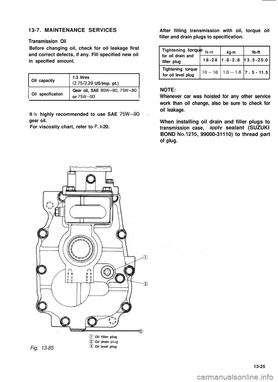
Fig. 13-85
@ Oil filler plug
@ Oil drain plup@ Oil level plug
After filling transmission with oil, torque oil
filler and drain plugs to specification.
Tightening torque N.m
for oil drain andkg-mlb-ft
filler plug18-28 1.8-2.8 13.5-20.0
Tightening torque
for oil level pluglo-161.0-1. 7.5-11.5
NOTE:
Whenever car was hoisted for any other service
work than oil change, also be sure to check for
oil leakage.
When installing oil drain and filler plugs to
transmission case,aipply sealant (SUZUKI
BOND No.1215, 99000-31110) to thread part
of plug.
13-25
Page 309 of 962
7) Install propeller shaft flanges and tighten
nuts to specified torque and talk the nuts.
8) Upon completion of entire assembly work,
install transfer in chassis body in reverse
sequence of removal. Pour gear oil into
transfer gear box.
Refer to information given in next oil and
oil capacity for oil to be used and specified
amount.
NOTE:
When installing oil filler and drain plugs to
transfer case, apply sealant (SUZUKI BOND
No.1215, 99000-31110) to thread part of plug.
14-9. MAINTENANCE SERVICES
Oil Level
Oil level must be checked with car held in
horizontal position in both front to rear and side
to side directions.
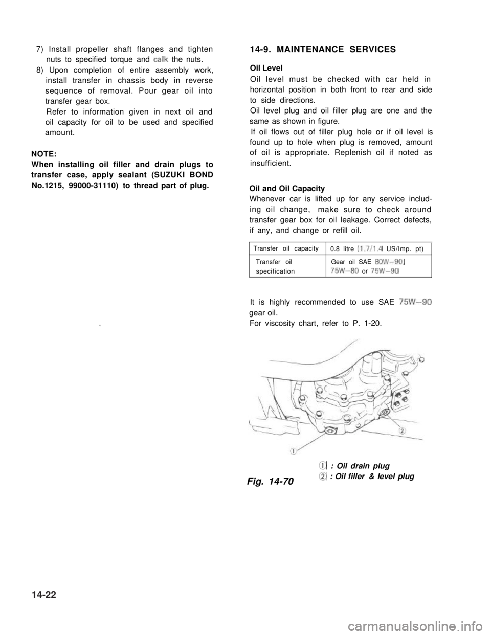
Oil level plug and oil filler plug are one and the
same as shown in figure.
If oil flows out of filler plug hole or if oil level is
found up to hole when plug is removed, amount
of oil is appropriate. Replenish oil if noted as
insufficient.
Oil and Oil Capacity
Whenever car is lifted up for any service includ-
ing oil change,make sure to check around
transfer gear box for oil leakage. Correct defects,
if any, and change or refill oil.
Transfer oil capacity0.8 litre (1.7/l .4 US/Imp. pt)
Transfer oilGear oil SAE 8OW-90,
specification75W-80 or 75W-90
It is highly recommended to use SAE 75W-90
gear oil.
For viscosity chart, refer to P. 1-20.
@ : Oil drain plug
Fig. 14-70@ : Oil filler & level plug
14-22
Page 334 of 962
16-7. MAINTENANCE SERVICES
Inspection
Inspect differential and differential housing for
evidence of oil leakage.
Oil level ‘is checked by means of its oil level
plug. Refer to p 1-20 for level inspection,
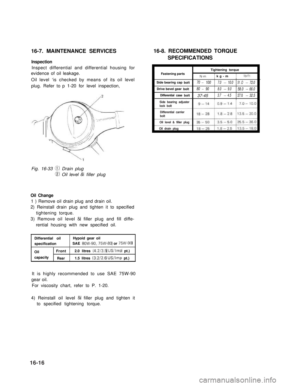
Fig. 16-33 @ Drain plug
CD Oil level & filler plug
Oil Change
1 ) Remove oil drain plug and drain oil.
2) Reinstall drain plug and tighten it to specified
tightening torque.
3) Remove oil level & filler plug and fill diffe-
rential housing with new specified oil.
Differential oilHypoid gear oil
specificationSAE 8OW-90,75W-80 or 75W-90
OilFront2.0 litres (4.2/3.5 US/Imp pt.)
capacityRear1.5 litres (3.2/2.6 US/Imp pt.)
It is highly recommended to use SAE 75W-90
gear oil.
For viscosity chart, refer to P. 1-20.
16-8. RECOMMENDED TORQUE
SPECIFICATIONS
ITightening torqueI
IFastening partsN.m1 kg-m 11
Side bearing capbolt70- 1007.0-10.051 .O-72.0
Drive bevel gearbolt80- 908.0-9.058.0-66.0
Differential casebolt37-453.7-4.527.0-32.5I
4) Reinstall oil level & filler plug and tighten it
to specified tightening torque.
16-16
Side bearing adjusterlock bolt
Differential carrier bolt
Oil level & filler plug
Oil drain plug
Page 392 of 962
![SUZUKI GRAND VITARA 1987 Service Repair Manual [Caliper OPERATION]
Single piston floating caliper type
The single piston floating caliper type brake is
employed in this model. One cylinder and one
piston are used for this type. (The cylinder is
co SUZUKI GRAND VITARA 1987 Service Repair Manual [Caliper OPERATION]
Single piston floating caliper type
The single piston floating caliper type brake is
employed in this model. One cylinder and one
piston are used for this type. (The cylinder is
co](/manual-img/20/57437/w960_57437-391.png)
[Caliper OPERATION]
Single piston floating caliper type
The single piston floating caliper type brake is
employed in this model. One cylinder and one
piston are used for this type. (The cylinder is
constructed as a monoblock with the caliper.)
Fluid pressure generated in the cylinder causes
the pad (1) on the piston side to press against
the disc. At the same time, the floating type
caliper body is moved to the right by the cylin-
der pressure, as shown in below figure, which
pulls pad (2) against the disc and so brakes the
wheel.
Caliper body
\Brake disc (rotor)
Fig. 19-6 - ’
The disc brake has no servo assistance as in drum
braking, and it is necessary to increase the work-
ing pressure of the piston and pad. For this pur-
pose, the wheel cylinder has a large bore. Even
only a little change in clearance between the disc
and pad has therefore a large influence on the
brake pedal stroke. It is necessary to have the
clearance adjusted to the minimum at all times,
by means of the piston (rubber) seal.
Piston seal (Rubber seal)Piston sealWinder (Rubber seal)
II
IPiston
Hydraulic pressure
“OFF“
Fig. 19-7
Clearance correction
Piston
Hydraulic pressure
“ON”
When oil pressure is applied to the piston, the
piston moves forward. The rubber seal, which
exerts considerable pressure against the piston,
moves with the cylinder. However, as a part of
the rubber seal has been fixed into a groove in
the cylinder, the shape of the rubber seal is dis-
torted toward internal end of the cylinder, as
shown in above figure. When pressure is taken
off from the foot brake pedal and fluid pressure
is released from the piston, a restoring force is
generated at the seal and pushes the piston back.
As the pads wear away and the clearance be-
tween the disc and pads becomes larger, the
piston moves a larger distance. The seal then
could change in shape further but, since the end
of the seal is fixed into the groove in the cylin-
der, the distortion is limited to the same amount
as previously described. The piston moves
further to cover the distance of clearance. The
piston returns by the same distance and the
rubber seal recovers its shape as described
above and thus the clearance between the disc
and pads are maintained in adjustment.
19-7
Cylinder