1987 SUZUKI GRAND VITARA check oil
[x] Cancel search: check oilPage 23 of 962
NOTE:
Steps 1) - 6) outlined above must be performed
with ENGINE NOT RUNNING. For step 7),
be sure to have adequate ventilation while
engine is running
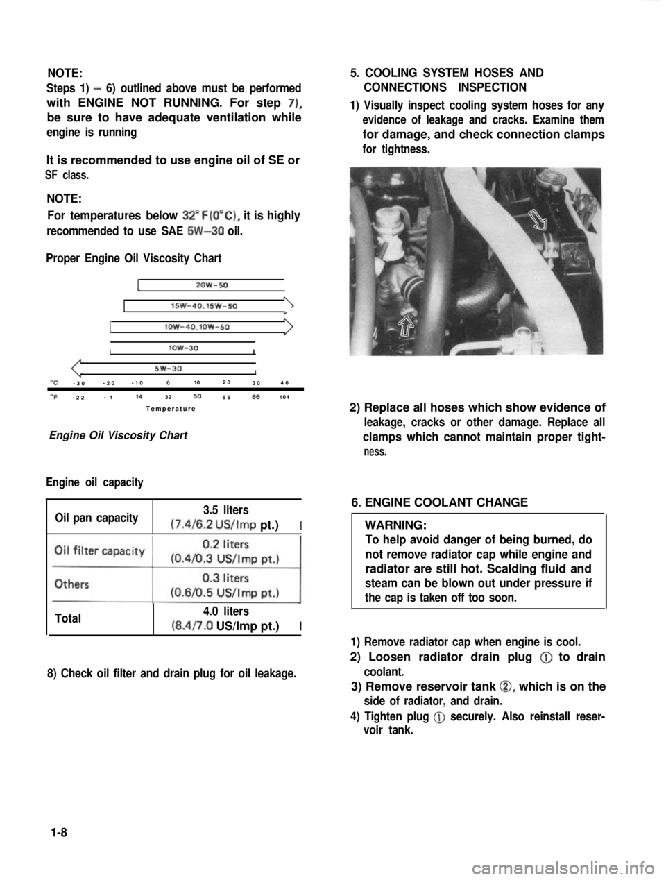
It is recommended to use engine oil of SE or
SF class.
NOTE:For temperatures below
32”F(O”C), it is highly
recommended to use SAE 5W-30 oil.
Proper Engine Oil Viscosity Chart
12OW-50
lSW-40.15w-501
Ilow-4O.lOW-50
Ilow-30I
5w-30I“C-3 0 -2
0 -1
0 0 102
0
30 4
0
OF-2 2 -
4 14
32506886104
Temperatur e
Engine Oil Viscosity Chart
Engine oil capacity
Oil pan capacity 3.5 liters (7.4/6.2
US/Imp pt.)I
Total 4.0 liters(8.4/7.0 US/Imp pt.)I
8) Check oil filter and drain plug for oil leakage.
5. COOLING SYSTEM HOSES AND
CONNECTIONS INSPECTION
1) Visually inspect cooling system hoses for any
evidence of leakage and cracks. Examine them
for damage, and check connection clamps
for tightness.
2) Replace all hoses which show evidence of
leakage, cracks or other damage. Replace all
clamps which cannot maintain proper tight-
ness.
6. ENGINE COOLANT CHANGE
WARNING:
To help avoid danger of being burned, do
not remove radiator cap while engine and
radiator are still hot. Scalding fluid and
steam can be blown out under pressure if
the cap is taken off too soon.
1) Remove radiator cap when engine is cool.
2) Loosen radiator drain plug @
to drain
coolant.
3) Remove reservoir tank 0, which is on the
side of radiator, and drain.
4) Tighten plug
@ securely. Also reinstall reser-
voir tank.
1-8
Page 24 of 962
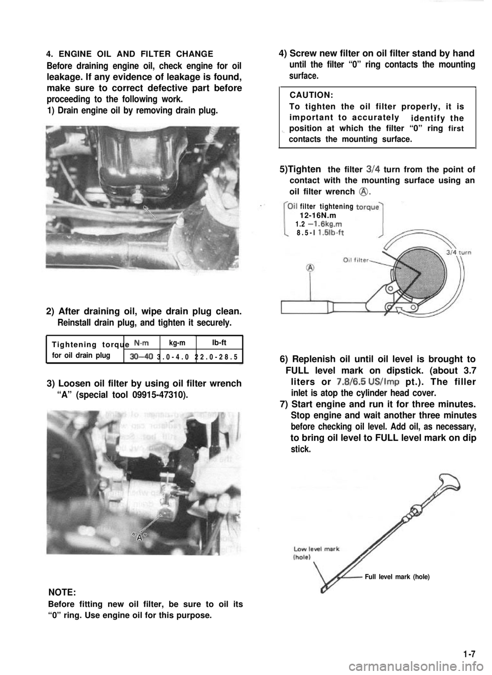
4. ENGINE OIL AND FILTER CHANGEBefore draining engine oil, check engine for oil
leakage. If any evidence of leakage is found,
make sure to correct defective part before
proceeding to the following work.
1) Drain engine oil by removing drain plug.
2) After draining oil, wipe drain plug clean.
Reinstall drain plug, and tighten it securely.
Tightening torque N-m kg-mlb-ft
for oil drain plug30-40 3.0-4.0 22.0-28.
5
3) Loosen oil filter by using oil filter wrench
“A” (special tool 09915-47310).
4) Screw new filter on oil filter stand by hand
until the filter “0” ring contacts the mounting
surface.
ICAUTION:
To tighten the oil filter properly, it is important to accurately identify the
1-position at which the filter “0” ring first
contacts the mounting surface.
5)Tighten the filter 3/4 turn from the point of
contact with the mounting surface using an
oil filter wrench
@.
filter tightening
12-16N.m
1.2
-1.6kg.m
8.5-l l.lilb-ft
6) Replenish oil until oil level is brought to
FULL level mark on dipstick. (about 3.7liters or 7.8/6.5
US/Imp pt.). The filler
inlet is atop the cylinder head cover.
7) Start engine and run it for three minutes.
Stop engine and wait another three minutes
before checking oil level. Add oil, as necessary,
to bring oil level to FULL level mark on dip
stick.
NOTE:
Before fitting new oil filter, be sure to oil its
“0” ring. Use engine oil for this purpose.
v
Full level mark (hole)
1-7
Page 29 of 962
NOTE:
When replacing plugs, make sure to use new
plugs of specified heat range and size.
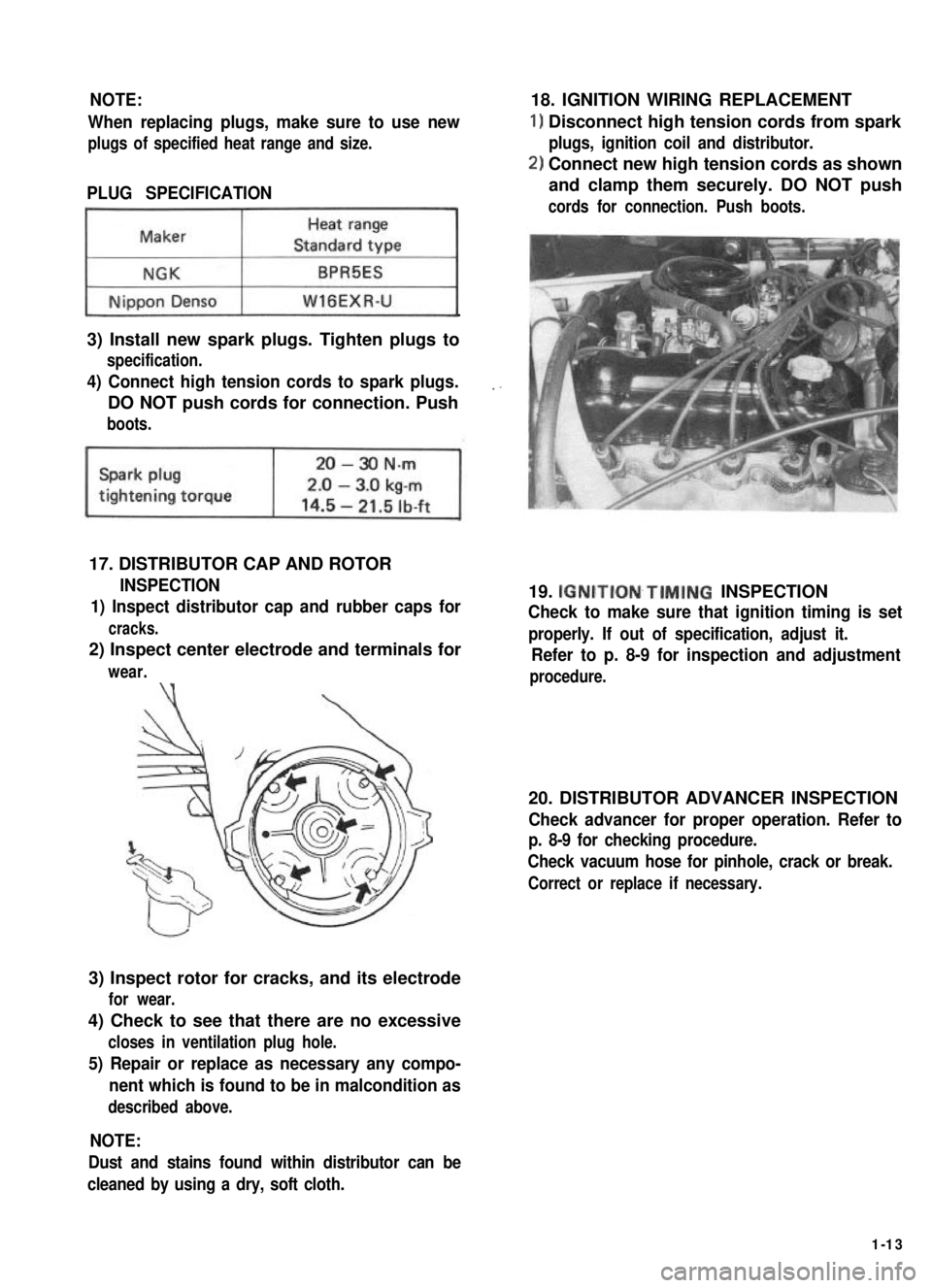
PLUG SPECIFICATION
~1
3) Install new spark plugs. Tighten plugs to
specification.
4) Connect high tension cords to spark plugs.
DO NOT push cords for connection. Push
boots.
17. DISTRIBUTOR CAP AND ROTOR
INSPECTION
1) Inspect distributor cap and rubber caps for
cracks.
2) Inspect center electrode and terminals for
wear.\‘(
3) Inspect rotor for cracks, and its electrode
for wear.
4) Check to see that there are no excessive
closes in ventilation plug hole.
5) Repair or replace as necessary any compo-
nent which is found to be in malcondition as
described above.
18. IGNITION WIRING REPLACEMENT
1) Disconnect high tension cords from spark
plugs, ignition coil and distributor.
2) Connect new high tension cords as shown
and clamp them securely. DO NOT push
cords for connection. Push boots.
19. IGNITION~TIMING INSPECTION
Check to make sure that ignition timing is set
properly. If out of specification, adjust it.
Refer to p. 8-9 for inspection and adjustment
procedure.
20. DISTRIBUTOR ADVANCER INSPECTION
Check advancer for proper operation. Refer to
p. 8-9 for checking procedure.
Check vacuum hose for pinhole, crack or break.
Correct or replace if necessary.
NOTE:
Dust and stains found within distributor can be
cleaned by using a dry, soft cloth.
1-13
Page 34 of 962
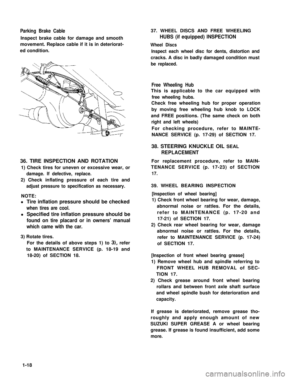
Parking Brake Cable
Inspect brake cable for damage and smooth
movement. Replace cable if it is in deteriorat-
ed condition.
36. TIRE INSPECTION AND ROTATION
1) Check tires for uneven or excessive wear, or
damage. If defective, replace.
2) Check inflating pressure of each tire and
adjust pressure to specification as necessary.
NOTE:
l Tire inflation pressure should be checked
when tires are cool.
l Specified tire inflation pressure should be
found on tire placard or in owners’ manual
which came with the car.
3) Rotate tires.
For the details of above steps 1) to 3), refer
to MAINTENANCE SERVICE (p. 18-19 and
18-20) of SECTION 18.
37. WHEEL DISCS AND FREE WHEELING
HUBS (if equipped) INSPECTION
Wheel Discs
Inspect each wheel disc for dents, distortion and
cracks. A disc in badly damaged condition must
be replaced.
Free Wheeling Hub
This is applicable to the car equipped with
free wheeling hubs.
Check free wheeling hub for proper operation
by moving free wheeling hub knob to LOCK
and FREE positions. (The same check on both
right and left wheels)
For checking procedure, refer to MAINTE-
NANCE SERVICE (p. 17-29) of SECTION 17.
38. STEERING KNUCKLE OIL SEAL
REPLACEMENT
For replacement procedure, refer to MAIN-
TENANCE SERVICE (p. 17-23) of SECTION
17.
39. WHEEL BEARING INSPECTION
[Inspection of wheel bearing]
1) Check front wheel bearing for wear, damage,
abnormal noise or rattles. For the details,
refer to MAINTENANCE (p. 17-20 and
17-21) of SECTION 17.
2) Check rear wheel bearing for wear, damage
abnormal noise or rattles. For the details,
refer to MAINTENANCE SERVICE (p. 17-24)
of SECTION 17.
[Inspection of front wheel bearing grease]
1) Remove wheel hub and spindle referring to
FRONT WHEEL HUB REMOVAL of SEC-
TION 17.
2) Check grease around front wheel bearing
rollars and between front axle shaft surface
and wheel spindle bush for deterioration and
capacity.
If grease is deteriorated, remove grease tho-
roughly and apply enough amount of new
SUZUKI SUPER GREASE A or wheel bearing
grease. If grease is found insufficient, add some
more.
1-18
Page 35 of 962
3) Install spindle, bearings, wheel hub, bearing
nut and brake disc referring to INSTALLA-
TION (p. 17-12) of SECTION 17.
4) Adjust bearing preload and then tighten
bearing lock nut to specification. Refer to
MAINTENANCE (p. 17-21) of SECTION 17.
5) Install drive flange or free wheeling hub (if
equipped), brake caliper with mounting and
wheel referring to INSTALLATION (p. 17-
12) of SECTION 17.
For tightening torque of each bolt and nut,
refer to torque table (p. 17-26) of SECTION
17.
40. SHOCK ABSORBERS INSPECTION
1) Inspect absorbers for evidence of oil leakage,
dents or any other damage on sleeves; and
inspect anchor ends for deterioration.
2) Depending on the results of the above inspec-
tion, replace absorbers.
2
1. Shock absorber
2. Leaf spring
WARNING:
When handling rear shock absorber in
which high-pressure gas is sealed, make
sure to observe the following precautions.
1. Don’t disassemble it.
2. Don’t put it into fire.
3. Don’t store it where it gets hot
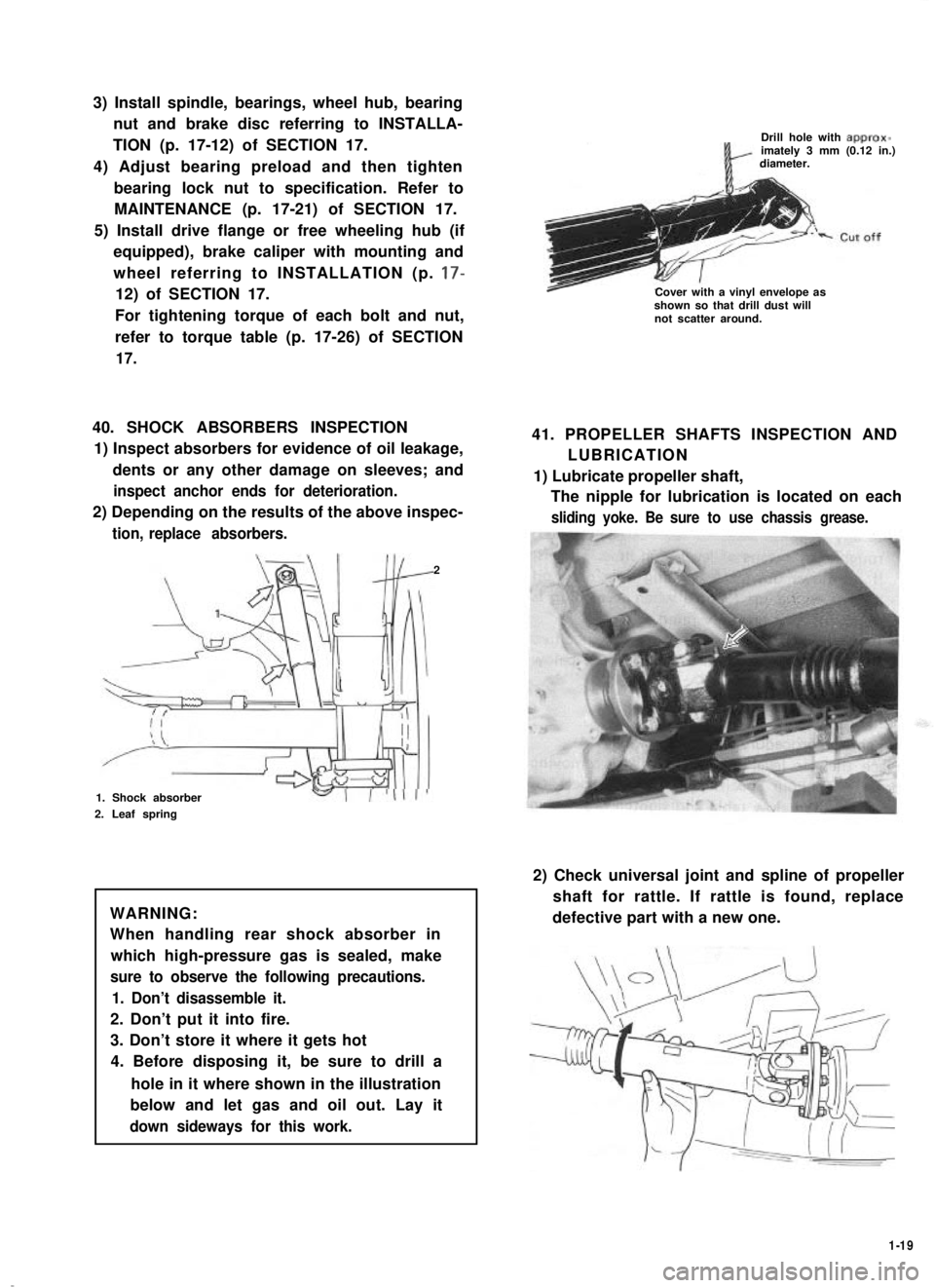
4. Before disposing it, be sure to drill a
hole in it where shown in the illustration
below and let gas and oil out. Lay it
down sideways for this work.
Drill hole with approx-imately 3 mm (0.12 in.)diameter.
Cover with a vinyl envelope asshown so that drill dust willnot scatter around.
41. PROPELLER SHAFTS INSPECTION AND
LUBRICATION
1) Lubricate propeller shaft,
The nipple for lubrication is located on each
sliding yoke. Be sure to use chassis grease.
2) Check universal joint and spline of propeller
shaft for rattle. If rattle is found, replace
defective part with a new one.
1-19
Page 36 of 962
3) Check propeller shaft (No. 1, No. 2, No. 3)
flange yoke bolts for tightness, and retighten
them as necessary:
N.mkg-mlb-ftTighteningtorque23-302.3-3.017.0-21.5
42. TRANSMISSION, TRANSFER,
DIFFERENTIAL OIL INSPECTION
AND CHANGE
[I nspectionl
1) Inspect transmission case, transfer case and
differential housing for evidence of oil leakage.
Repair leaky point if any.
2) Make sure that the car is placed level for oil
level check.
3) Remove each level plug of transmission,
transfer and differential (front and rear).
In any of these cases, oil level can be checked
roughly by means of level plug hole. That is,
,if oil flows out of level plug hole or if oil
level is found up to hole when level plug is
removed, oil is properly filled.
If oil is found insufficient, pour specified
amount of specified oil as given in the below
table.
[Change]
Oil change procedure is as follows.
Place the car level and drain oil by removing
drain plug. Pour specified amount of specified
oil as in the below table and tighten drain plug
and filler plug to specified torque.
It is highly recommended to use SAE 75W-90
gear oil.
Viscosity chart
SAE
75w-ao,75w-90
"C -30 --20 -10 0 10 20 30 40"F -22 -4lb 32 50 68 86104
Temperature
Transmission oil change
Oil capacity
Type of oil
1.3 liters
(2.7/2.3 US/Imp pt.)
Gear oil, SAE
8OW-90,75W-80 or
75w-90
l-20
18-28N.m
I ”’
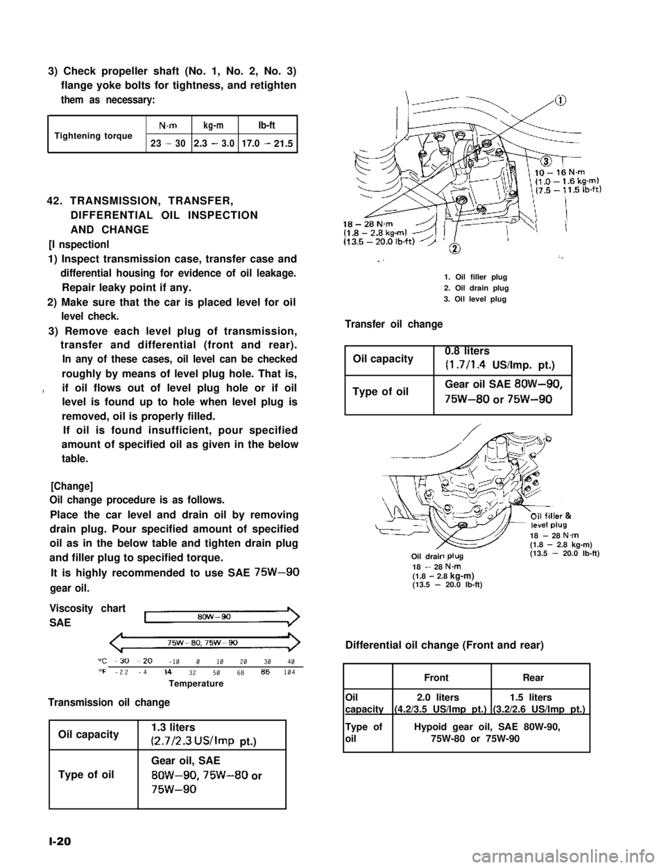
1. Oil filler plug
2. Oil drain plug
3. Oil level plug
Transfer oil change
Oil capacity0.8 liters
(1.7/l .4 US/Imp. pt.)
Type of oilGear oil SAE 8OW-90,
75W-80 or 75W-90
18 - 28 N.m(1.8 - 2.8 kg-m)(13.5 - 20.0 lb-ft)-R-Oil drair18 - 28 N&(1.8 - 2.8 kg-m)(13.5 - 20.0 lb-ft)
Differential oil change (Front and rear)
1.5 liters
(3.2/2.6 US/Imp pt.)
2.0 liters
(4.2/3.5 US/Imp pt.)
FrontRear
Oil
capacity
Type of
oil
Hypoid gear oil, SAE 80W-90,
75W-80 or 75W-90
Page 37 of 962
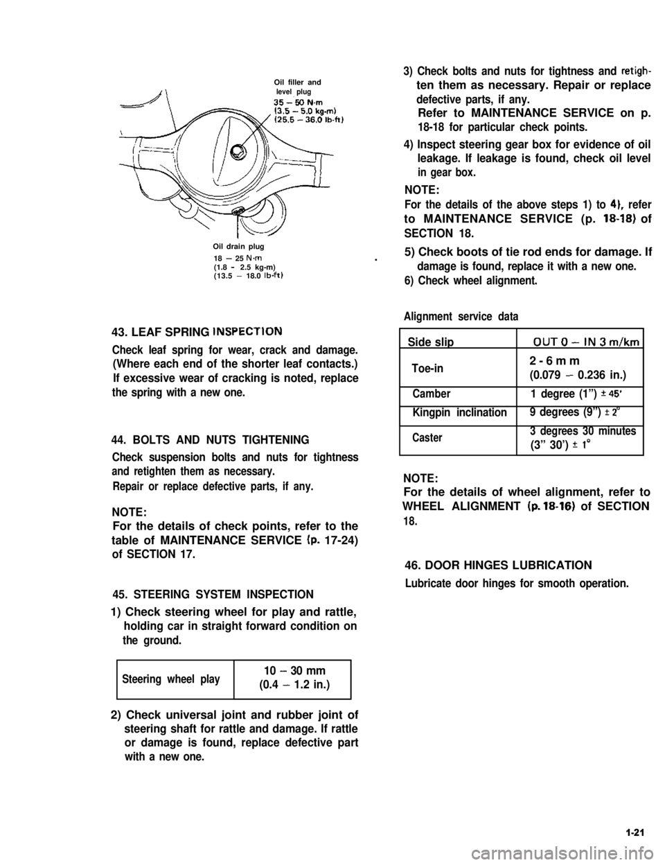
Oil filler andlevel plug
Oil drain plug
18 - 25 N.m(1.8 - 2.5 kg-m)(13.5 - 18.0 lb-ft)
43. LEAF SPRING lNSPECTlON
Check leaf spring for wear, crack and damage.
(Where each end of the shorter leaf contacts.)
If excessive wear of cracking is noted, replace
the spring with a new one.
44. BOLTS AND NUTS TIGHTENING
Check suspension bolts and nuts for tightness
and retighten them as necessary.
Repair or replace defective parts, if any.
NOTE:
For the details of check points, refer to the
table of MAINTENANCE SERVICE (p. 17-24)
of SECTION 17.
45. STEERING SYSTEM INSPECTION
1) Check steering wheel for play and rattle,
holding car in straight forward condition on
the ground.
Steering wheel play10 - 30 mm
(0.4 - 1.2 in.)
3) Check bolts and nuts for tightness and retigh-
ten them as necessary. Repair or replace
defective parts, if any.
Refer to MAINTENANCE SERVICE on p.
18-18 for particular check points.
4) Inspect steering gear box for evidence of oil
leakage. If leakage is found, check oil level
in gear box.
NOTE:
For the details of the above steps 1) to 41, refer
to MAINTENANCE SERVICE (p. 18-18) of
SECTION 18.
.5) Check boots of tie rod ends for damage. If
damage is found, replace it with a new one.
6) Check wheel alignment.
Alignment service data
Side slipOUTO-IN3m/km
Toe-in2-6mm
(0.079 - 0.236 in.)
Camber1 degree (1”) *45’
Kingpin inclination 9 degrees (9”) f 2’
Caster3 degrees 30 minutes
(3” 30’) f I0
NOTE:
For the details of wheel alignment, refer to
WHEEL ALIGNMENT (p. 18-16) of SECTION
18.
46. DOOR HINGES LUBRICATION
Lubricate door hinges for smooth operation.
2) Check universal joint and rubber joint of
steering shaft for rattle and damage. If rattle
or damage is found, replace defective part
with a new one.
1-21
Page 40 of 962

2-1. ENGINE
Cond it ion
Poor starting
(Hard starting)
Possible cause
Starter will not run
1. Main fuse blown off
2. Contact not closing in main switch, or this
switch open-circuited
3. Run-down battery
4. Defective magnetic switch of starter
5. Loose battery terminal connection
6. Defective brushes in starter
7. Loose battery cord connection
8. Open in field or armature circuit of starter.
Correction
Replace
Repair or replace
Recharge
Replace
Clean and retighten
Replace
Retighten
Repair or replace
No sparking
1. Defective spark plugAdjust gap, or replace
2. High tension cord short-circuited (grounded)Repair or replace
3. Cracked rotor or cap in distributorReplace
4. Defective signal generator or ignitorReplace
5. Maladjusted signal rotor air gap.Adjust
6. Contact not closing positively in main switch,Replace
or this switch open-circuited
7. Loose or blown fuseSet right or replace
8. Improper ignition timingAdjust
9. Defective ignition coil.Replace
Faulty intake and exhaust systems
1. Carburetor out of adjustment
2. Fuel pump not discharging adequately
3. Clogged fuel filter
4. Defective choke mechanism
5. Loose intake manifold
6. Dirty and clogged carburetor
7. Float level out of adjustment
8. Clogged fuel hose or pipe
9. Not enough fuel in the tank
10. Malfunctioning fuel cut solenoid valve
Adjust
Replace
Clean, or replace
Repair or replace
Retighten
Disassemble and clean
Adjust
Clean or replace
Refill
Check solenoid valve for
proper operation and
replace if necessary
Abnormal engine internal condition
1. Ruptured cylinder head gasket
2. Improper valve clearance
3. Weakened or broken valve spring
4. Loose manifold, permitting air to be
drawn in
5. Worn pistons, rings or cylinders
Replace
Adjust
Replace
Retighten and, as neces-
sary, replace gasket
Replace worn rings and
pistons and rebore as
necessary
2-2