1987 SUZUKI GRAND VITARA parking brake
[x] Cancel search: parking brakePage 31 of 962
1) Replace fuel hoses (pipe to fuel pump, pipe to
fuel filter and breather hose) in fuel feed and
return lines with new ones.
2) Remove fuel tank.
3) Replace return hose (tank to return pipe)
with new one.
4) Clamp hoses securely.
5) Install fuel tank referring to p. 4-35.
6) After installation, start engine and check it
for leaks.
27. IDLE SPEED INSPECTION
NOTE:
Before starting engine, place transmission gear
shift lever in “Neutral”, and set parking brake
and block drive wheels.
1) Warm up engine to normal operating tempe-
rature.
2) Check to ensure that idle speed is within
750 - 850 r/min (rpm).
3) If idle speed is not within specified range,
adjust idle speed. Refer to MAINTENANCE
SERVICE (p. 4-26) for procedures to check
and adjust idle speed.
28. IDLE MIXTURE INSPECTION
1) Warm up engine to normal operating tem-
perature.
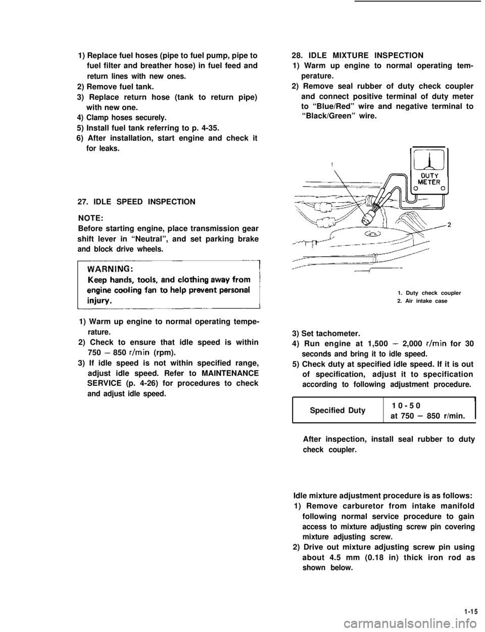
2) Remove seal rubber of duty check coupler
and connect positive terminal of duty meter
to “Blue/Red” wire and negative terminal to
“Black/Green” wire.
1
1. Duty check coupler
2. Air intake case
3) Set tachometer.
4) Run engine at 1,500 - 2,000 r/min for 30
seconds and bring it to idle speed.
5) Check duty at specified idle speed. If it is out
of specification,adjust it to specification
according to following adjustment procedure.
Specified Duty10-50
at 750 - 850 r/min.I
After inspection, install seal rubber to duty
check coupler.
Idle mixture adjustment procedure is as follows:
1) Remove carburetor from intake manifold
following normal service procedure to gain
access to mixture adjusting screw pin covering
mixture adjusting screw.
2) Drive out mixture adjusting screw pin using
about 4.5 mm (0.18 in) thick iron rod as
shown below.
1-15
Page 32 of 962
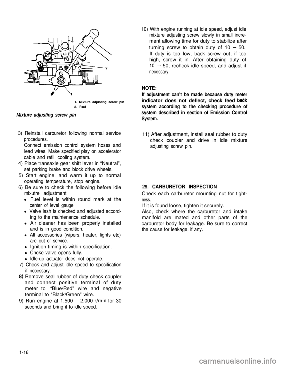
1. Mixture adjusting screw pin
2. Rod
Mixture adjusting screw pin
10) With engine running at idle speed, adjust idle
mixture adjusting screw slowly in small incre-
ment allowing time for duty to stabilize after
turning screw to obtain duty of 10 - 50.
If duty is too low, back screw out; if too
high, screw it in. After obtaining duty of
10- 50, recheck idle speed, and adjust if
necessary.
NOTE:
If adjustment can’t be made because duty meter
indicator does not deflect, check feed baCk
system according to the checking procedure of
system described in section of Emission Control
System.
3) Reinstall carburetor following normal service
procedures.
Connect emission control system hoses and
lead wires. Make specified play on accelerator
cable and refill cooling system.
11) After adjustment, install seal rubber to duty
check coupler and drive in idle mixture
adjusting screw pin.
4) Place transaxle gear shift lever in “Neutral”,
set parking brake and block drive wheels.
5) Start engine, and warm it up to normal
operating temperature, stop engine.
6) Be sure to check the following before idle
mixutre adjustment.
l Fuel level is within round mark at the
center of level gauge.
l Valve lash is checked and adjusted accord-
ing to the maintenance schedule.
l Air cleaner has been properly installed
and is in good condition.
l All accessories (wipers, heater, lights etc)
are out of service.
29. CARBURETOR INSPECTION
Check each carburetor mounting nut for tight-
ness.
If it is found loose, tighten it securely.
Also, check where the carburetor and intake
manifold are mated and other parts of the
carburetor body for leakage. Be sure to correct
the cause for leakage, if any.
l Ignition timing is within specification.
l Choke valve opens fully.
l Idle-up actuator does not operate.
7) Check and adjust idle speed to specification
if necessary.
8) Remove seal rubber of duty check coupler
and connect positive terminal of duty
meter to“Blue/Red” wire and negative
terminal to “Black/Green” wire.
9) Run engine at 1,500 - 2,000 r/min for 30
seconds and bring it to idle speed.
1-16
Page 33 of 962
1-3. CHASSIS AND BODY
30. CLUTCH PEDAL INSPECTION
1) Check clutch pedal height. It should be the
same as brake pedal height.
2) Check clutch pedal free travel.
Clutch pedal free travel20 - 30 mm
(0.8 - 1.1 in.)
For the details of the above steps 1) and 2),
refer to MAINTENANCE SERVICE (p. 11-8) of
SECTION 11.
31. BRAKE DISCS, PADS, BRAKE DRUMS
AND SHOES INSPECTION
Brake Discs and Pads
I) Remove wheel and caliper but don’t discon-
nect brake hose from caliper.
2) Check front disc brake pads and discs for
excessivewear,damageand deflection.
Replace parts as necessary. For the details,
refer to p. 19-I 6 and 19-I 7 of SECT ION 19.
Be sure to torque caliper guide pins to specifi-
cation for reinstallation.
Brake Drums and Shoes
I) Remove wheel and brake drum.
2) Check rear brake drums and brake linings for
excessive wear and damage, while wheels and
drums are removed. Also check wheel cylin-
ders for leaks, at the same time. Replace
these parts as necessary.
For the details, refer to p. 19-21 and p. 19-
22 of SECTION 19.
32. BRAKE HOSES AND PIPES INSPECTION
Check brake hoses and pipes for proper hook-
up, leaks, cracks, chafing and other damage.
Replace any of these parts as necessary.
CAUTION:
After replacing any brake pipe or hose, be
sure to carry out air purge operation.
33. BRAKE FLUID INSPECTION AND
CHANGE
[INSPECTION]
1) Check around master cylinder and reservoir
for fluid leakage.
If found leaky, correct.
2) Check fluid level
If fluid level is lower than the minimum level
of reservoir, refilling is necessary. Fill reservoir
with specified brake fluids.
Brake fluid Speifi;t3ons
For the details, refer to MAINTENANCE
SERVICE (p. 19-42) of SECTION 19.
CAUTION:
Since the brake system of this car is factory-
filled with glycol-base brake fluid, do not
use or mix different type of fluid when
refilling the system; otherwise serious
damage will occur. Do not use old or used
brake fluid, or one taken from unsealed
container.
[CHANGE]
1) Change brake fluid. As fluid change procedure,
drain existing fluid from brake system com-
pletely, fill the system with above recom-
mended fluid and carry out air purge opera-
tion.
For description of air purge, refer to p. 19-46
and 19-47 of SECTION 19.
34. BRAKE PEDAL INSPECTION
Check brake pedal travel.
For -checking procedure, refer to PEDAL TRA-
VEL CHECK (p. 19-43) of SECTION 19.
35. BRAKE LEVER AND CABLE
INSPECTION
Parking Brake Lever
I) Check tooth tip of each notch for damage or
wear. If any damage or wear is found, replace
parking lever.
2) Check parking brake lever for proper opera-
tion and stroke, and adjust it if necessary.
For checking and adjusting procedures,
refer to PARKING BRAKE INSPECTION
AND ADJUSTMENT (p. 19-44) of SECTION
19.
1-17
Page 34 of 962
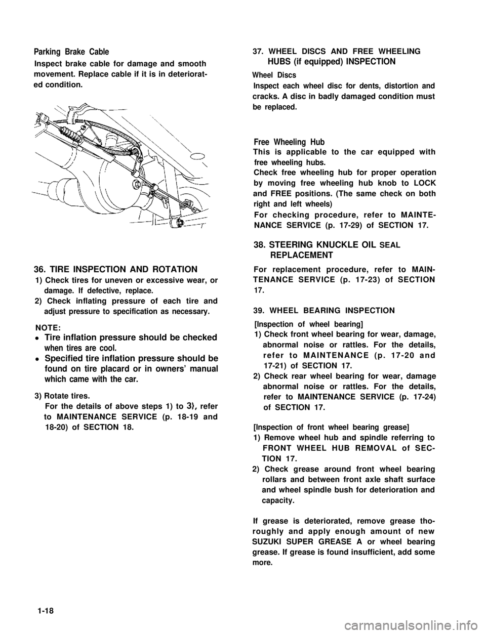
Parking Brake Cable
Inspect brake cable for damage and smooth
movement. Replace cable if it is in deteriorat-
ed condition.
36. TIRE INSPECTION AND ROTATION
1) Check tires for uneven or excessive wear, or
damage. If defective, replace.
2) Check inflating pressure of each tire and
adjust pressure to specification as necessary.
NOTE:
l Tire inflation pressure should be checked
when tires are cool.
l Specified tire inflation pressure should be
found on tire placard or in owners’ manual
which came with the car.
3) Rotate tires.
For the details of above steps 1) to 3), refer
to MAINTENANCE SERVICE (p. 18-19 and
18-20) of SECTION 18.
37. WHEEL DISCS AND FREE WHEELING
HUBS (if equipped) INSPECTION
Wheel Discs
Inspect each wheel disc for dents, distortion and
cracks. A disc in badly damaged condition must
be replaced.
Free Wheeling Hub
This is applicable to the car equipped with
free wheeling hubs.
Check free wheeling hub for proper operation
by moving free wheeling hub knob to LOCK
and FREE positions. (The same check on both
right and left wheels)
For checking procedure, refer to MAINTE-
NANCE SERVICE (p. 17-29) of SECTION 17.
38. STEERING KNUCKLE OIL SEAL
REPLACEMENT
For replacement procedure, refer to MAIN-
TENANCE SERVICE (p. 17-23) of SECTION
17.
39. WHEEL BEARING INSPECTION
[Inspection of wheel bearing]
1) Check front wheel bearing for wear, damage,
abnormal noise or rattles. For the details,
refer to MAINTENANCE (p. 17-20 and
17-21) of SECTION 17.
2) Check rear wheel bearing for wear, damage
abnormal noise or rattles. For the details,
refer to MAINTENANCE SERVICE (p. 17-24)
of SECTION 17.
[Inspection of front wheel bearing grease]
1) Remove wheel hub and spindle referring to
FRONT WHEEL HUB REMOVAL of SEC-
TION 17.
2) Check grease around front wheel bearing
rollars and between front axle shaft surface
and wheel spindle bush for deterioration and
capacity.
If grease is deteriorated, remove grease tho-
roughly and apply enough amount of new
SUZUKI SUPER GREASE A or wheel bearing
grease. If grease is found insufficient, add some
more.
1-18
Page 38 of 962

FINAL INSPECTION
Carry out road test in safe place.
WARNING:
When carrying out the following road
tests, select a safe place where no man or
no running car is seen so as to prevent any
accident.
1) Engine start
Check engine start for readiness.
2) Clutch
Check the following:
l that clutch is completely released when
depressing clutch pedal,
l that no slipping clutch occurs when releas-
ing pedal and accelerating,
l and that clutch itself is free from any
abnormal condition.
3) Gearshift Lever (Transmission and Transfer)
Check gearshift lever for smooth shifting
to all positions and for good performance of
transmission and transfer in any position.
4) Brake
[Foot brake]
Check the following when depressing brake
pedal while driving;
l that brake works properly,
l that it is free from noise,
l and that braking force applies equally on
all wheels.
[Parking brake]
Check to ensure that parking brake is fully
effective when the car is stopped on the slop
and brake lever is pulled all the way.
5) Steering
Check to ensure that steering wheel is free
from instability, or abnormally heavy feeling
while driving.
1-22
Page 51 of 962

Condition
Excessive pedal travel
(Pedal stroke too
large)
Possible cause
1. Partial brake system failure
2. Insufficient fluid in master
cylinder reservoirs
Correction
Check diagonal brake systems and
repair as necessary
Fill reservoirs with approved brake
fluid. Check for leaks and air in
brake systems. Check warning light.
Bleed system if necessary.
3. Air in system (Pedal soft/spongy)Bleed system
4. Rear brake system not adjustedAdjust rear brakes (Repair auto
(malfunctioning auto adjustingadjusting mechanism)
mechanism)
5. Bent brake shoesReplace brake shoes
6. Worn rear brake shoesReplace brake shoes.
Dragging brakes (A
very light drag is pre-
sent in all disc brakes
immediately after
pedal is released)
1. Master cylinder pistons not
returning correctly
2. Clogged return port in master
cylinder
3. Restricted brake tubes or hoses
4. Incorrect parking brake
adjustment
5. Weakened or broken return
springs in the brake
Repair master cylinder
Clean
Check for soft hoses or damaged tubes
and replace with new hoses and/or
new double-walled steel brake tubing
Check and adjust to correct specifica-
tions
Replace
6. Sluggish parking-brake cables or
linkage
Repair or replace
7. Wheel cylinder or caliper piston
sticking
Repair as necessary
Pedal pulsation1. Damaged or loose wheel bearingsReplace wheel bearings
(Pedal pulsates when2. Excessive disc lateral runout Check per instructions. If not within
depressed for braking)specifications, replace or machine the
disc.
3. Parallelism not within specifica-Check per instructions. If not within
tionsspecifications, replace or machine the
disc.
4. Rear drums out of roundCheck runout.
Braking noise1. Glazed shoe linings, or foreignRepair or replace shoe lining
matters stuck to linings
2. Worn or distorted shoe liningsReplace shoe lining (or pad)
3. Loose front wheel bearingsReplace wheel bearings
4. Distorted backing plates or looseReplace or retighten securing bolts
mounting bolts
2-13
Page 141 of 962
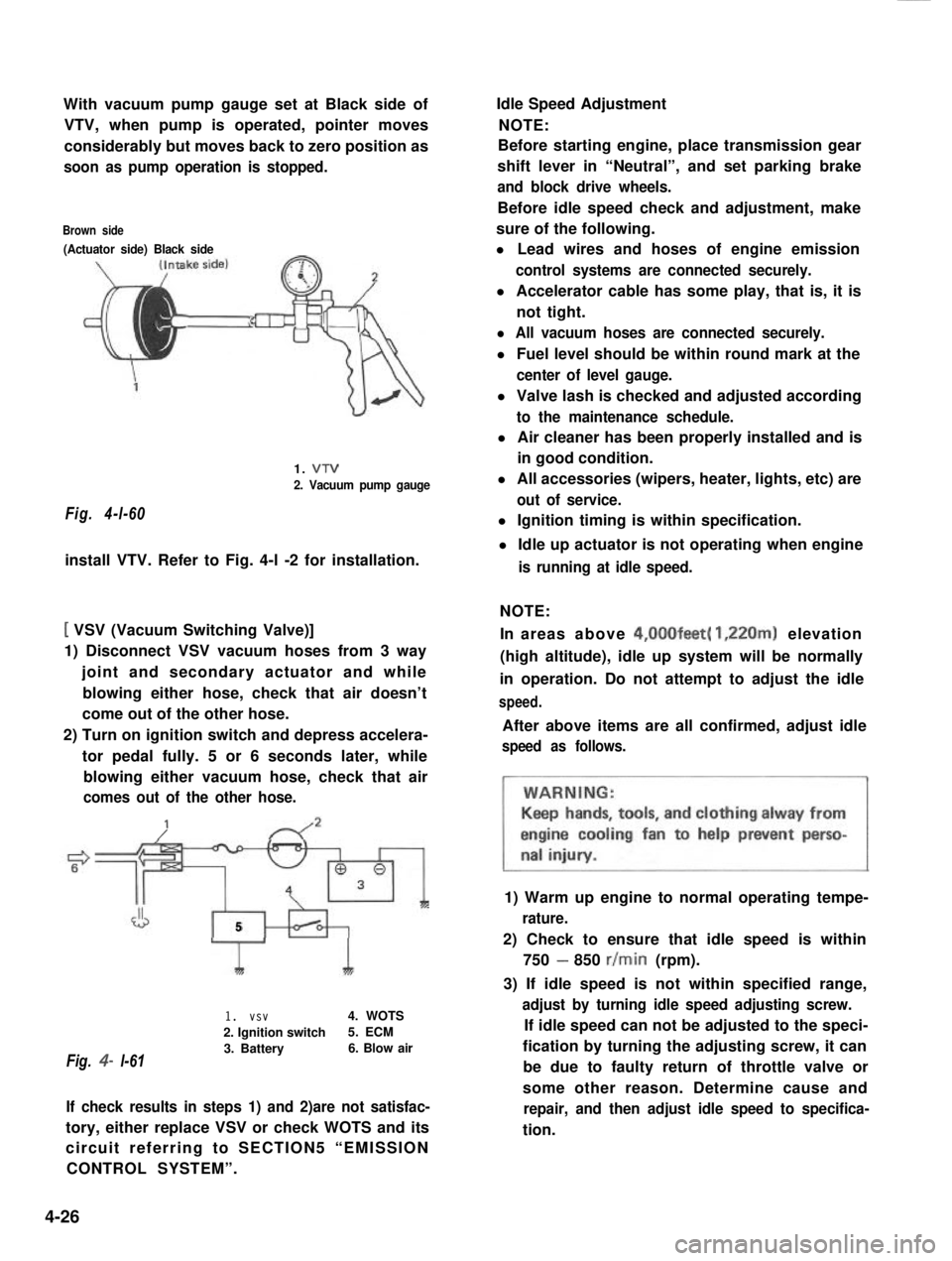
With vacuum pump gauge set at Black side of
VTV, when pump is operated, pointer moves
considerably but moves back to zero position as
soon as pump operation is stopped.
Brown side
(Actuator side) Black side
Fig. 4-l-60
1. VTV
2. Vacuum pump gauge
install VTV. Refer to Fig. 4-l -2 for installation.
[ VSV (Vacuum Switching Valve)]
1) Disconnect VSV vacuum hoses from 3 way
joint and secondary actuator and while
blowing either hose, check that air doesn’t
come out of the other hose.
2) Turn on ignition switch and depress accelera-
tor pedal fully. 5 or 6 seconds later, while
blowing either vacuum hose, check that air
comes out of the other hose.
J5
Fig. 4- l-61
1I
1. vsv4. WOTS
2. Ignition switch5. ECM
3. Battery6. Blow air
If check results in steps 1) and 2)are not satisfac-
tory, either replace VSV or check WOTS and its
circuit referring to SECTION5 “EMISSION
CONTROL SYSTEM”.
Idle Speed Adjustment
NOTE:
Before starting engine, place transmission gear
shift lever in “Neutral”, and set parking brake
and block drive wheels.
Before idle speed check and adjustment, make
sure of the following.
l Lead wires and hoses of engine emission
control systems are connected securely.
l Accelerator cable has some play, that is, it is
not tight.
l All vacuum hoses are connected securely.
l Fuel level should be within round mark at the
center of level gauge.
l Valve lash is checked and adjusted according
to the maintenance schedule.
l Air cleaner has been properly installed and is
in good condition.
l All accessories (wipers, heater, lights, etc) are
out of service.
l Ignition timing is within specification.
l Idle up actuator is not operating when engine
is running at idle speed.
NOTE:
In areas above 4,00Ofeet( 1,220m) elevation
(high altitude), idle up system will be normally
in operation. Do not attempt to adjust the idle
speed.
After above items are all confirmed, adjust idle
speed as follows.
1) Warm up engine to normal operating tempe-
rature.
2) Check to ensure that idle speed is within
750 - 850 r/min (rpm).
3) If idle speed is not within specified range,
adjust by turning idle speed adjusting screw.
If idle speed can not be adjusted to the speci-
fication by turning the adjusting screw, it can
be due to faulty return of throttle valve or
some other reason. Determine cause and
repair, and then adjust idle speed to specifica-
tion.
4-26
Page 143 of 962

3) Reinstall carburetor following normal service
procedures.
Connect emission control system hoses and
lead wires. Make specified play on accelerator
cable and refill cooling system.
4) Place transaxle gear shift lever in “Neutral”,
set parking brake and block drive wheels.
5) Start engine, and warm it up to normal
operating temperature, stop engine.
6) Be sure to check the following before idle
mixture adjustment.
l Fuel level is within round mark at the
center of level gauge.
l Valve lash is checked and adjusted accord-
ing to the maintenance schedule.
l Air cleaner has been properly installed
and is in good condition.
l All accessories (wipers, heater, lights etc)
are out of service.
l Ignition timing is within specification.
l Choke valve opens fully.
l Idle-up actuator does not operate.
7) Check and adjust idle speed to specification
if necessary.
8) Remove seal rubber of duty check coupler
and connect positive terminal of duty
meter to“Blue/Red” wire and negative
terminal to “Black/Green” wire.
9) Run engine at 1,500 - 2,000 r/min for 30
seconds and bring it to idle speed.
10) With engine running at idle speed, adjust idle
mixture adjusting screw slowly in small incre-
ment allowing time for duty to stabilize after
turning screw to obtain duty of 10 - 50.
If duty is too low, back screw out; if too
high, screw it in. After obtaining duty of
10 - 50, recheck idle speed, and adjust if
necessary.
NOTE:
If adjustment can’t be made because duty meter
indicator does not deflect, check feed back
system according to the checking procedure of
system described in section of Emission Control
System.
11) After adjustment, install seal rubber to duty
check coupler and drive in idle mixture
adjusting screw pin.
4-28