1987 SUZUKI GRAND VITARA parking brake
[x] Cancel search: parking brakePage 244 of 962
![SUZUKI GRAND VITARA 1987 Service Repair Manual [Carrier and hold-down]
The battery carrier and hold-down clamp should
be clean and free from corrosion before instal-
ling the battery. The carrier should be in good
condition so that it will support SUZUKI GRAND VITARA 1987 Service Repair Manual [Carrier and hold-down]
The battery carrier and hold-down clamp should
be clean and free from corrosion before instal-
ling the battery. The carrier should be in good
condition so that it will support](/manual-img/20/57437/w960_57437-243.png)
[Carrier and hold-down]
The battery carrier and hold-down clamp should
be clean and free from corrosion before instal-
ling the battery. The carrier should be in good
condition so that it will support the battery
securely and keep it level.
Make certain there are no parts in carrier before
installing the battery.
To prevent the battery from shaking in its
carrier, the hold-down bolts should be tight but
not over tightened.
[Visual inspection]
Check for obvious damage, such as cracked or
broken case or cover, that could permit loss of
electrolyte. If obvious damage is noted, replace
the battery. Determine cause of damage and
correct as needed.
Check the battery terminal and cords for corro-
sion. If any, it should be cleaned.
[Built-in indicator]
This sealed battery has a built-in temperature
compensated indicator in the top of the battery.
This indicator is to be used with the following
diagnostic procedure. When observing the
indicator, make sure that the battery has a clean
top. A light may be needed in some poorly-lit
areas.
Under normal operation, two indications can
be seen
2
Clear
RedCHARGING
NECESSARY
Fig. lo-23
l Clear with Red Dot
This means the discharging battery. In this case,
charge the battery until the indicator will be
blue with red dot. The charging and electrical
systems should also be checked at this time. If
any defective is found, correct it. While charging
it, if the battery feels hot 52°C (125” F), or if
violent gassing or spewing of electrolyte through
the vent hole occurs, discontinue charging or
reduce charging rate.
[Jump starting in case of emergency with
auxiliary (booster) battery]
NOTE:
l Do not push or tow the vehicle to start.
Damage to the emission system and/or to
other parts of the vehicle may result.
8 Both booster and discharged battery should
be treated carefully when using jumper cables.
Follow the procedure outlined below, being
careful not to cause sparks:
CAUTION:
l Departure from these conditions or the
procedure below could result in: (1)
Serious personal injury (particularly to
eyes) or property damage from such
causes as battery explosion, battery acid,
or electrical burns; and/or (2) damage to
electronic components of either vehicle.
l Never expose battery to open flame or
electric spark-batteries generate a gas
which is flammable and explosive.
l Remove rings,watches,and other
jewelry. Wear approved eye protection.
l Do not allow battery fluid to contact
eyes, skin, fabrics, or painted surfaces -
fluid is a corrosive acid. Flush any con-
tacted area with water immediately and
thoroughly. Be careful that metal tools
or jumper cables do not contact the
positive battery terminal (or metal in
contact with it) and any other metal on
the car, because a short circuit could
occur. Batteries should always be kept
out of the reach of children.
1) Set parking brake and place transmission in
neutral. Turn off the ignition, turn off lights
and all other electrical loads.
2) Check electrolyte level. If level is below low
level line, replace battery.
NOTE:
When jump starting an engine with charging
equipment, be sure equipment used is 12volt
and negative ground. Do not use 24volt charging
equipment. Using each equipment can cause
serious damage to the electrical system or
electronic parts.
10-11
Page 322 of 962
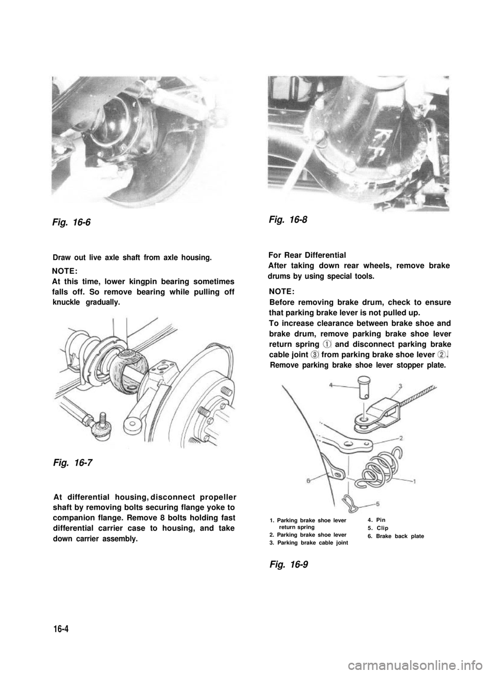
Fig. 16-6Fig. 16-8
Draw out live axle shaft from axle housing.
NOTE:
At this time, lower kingpin bearing sometimes
falls off. So remove bearing while pulling off
knuckle gradually.
Fig. 16-7
At differential housing, disconnect propeller
shaft by removing bolts securing flange yoke to
companion flange. Remove 8 bolts holding fast
differential carrier case to housing, and take
down carrier assembly.
For Rear Differential
After taking down rear wheels, remove brake
drums by using special tools.
NOTE:
Before removing brake drum, check to ensure
that parking brake lever is not pulled up.
To increase clearance between brake shoe and
brake drum, remove parking brake shoe lever
return spring @ and disconnect parking brake
cable joint @ from parking brake shoe lever 0.
Remove parking brake shoe lever stopper plate.
1. Parking brake shoe leverreturn spring2. Parking brake shoe lever 3. Parking brake cable joint
4. Pin
5. Clip
6. Brake back plate
Fig. 16-9
16-4
Page 386 of 962
SECTION 19
BRAKES
CONTENTS
19-1. GENERAL DESCRIPTION................................. 19-2
19-2. FRONT DISC BRAKE..................................... 19-14
19-3. REAR DRUM BRAKE..................................... 19-20
19-4. MASTER CYLINDER..................................... 19-27
19-5. BRAKE BOOSTER....................................... 19-30
19-6. PARKING BRAKE........................................ 19-38
19-7. BRAKE PIPES AND HOSES . . . . . . . . . . . . . . . . . . . . . . . . . . . . . . . 19-39
19-8. MAINTENANCE SERVICE . . . . . . . . . . . . . . . . . . . . . . . . . . . . . . . . 19-42
19-9. TORQUE SPECIFICATION.. . . . . . . . . . . . . . . . . . . . . . . . . . . . . . . 19-49
NOTE:
All brake fasteners are important attaching parts in that they could affect the performance
of vital parts and systems, and/or could result in major repair expense. They must be
replaced with one of same part number or with an equivalent part if replacement becomes
necessary. Do not use a replacement part of lesser quality or substitute design. Torque
values must be used as specified during reassembly to assure proper retention of all parts.
There is to be no welding as it may result in extensive damage and weakening of the
metal.
WARNING:
When servicing wheel brake parts, do not create dust by grinding, sanding brake linings,
or by cleaning wheel brake parts with a dry brush or with compressed air. Many wheel
brake parts contain asbestos fibers which can become airborned if dust is created dur-
ing servicing. Breathing dust containing asbestos fibers may cause serious bodily harm.
A water dampened cloth or water based solution should be used to remove any dust
on brake parts. Equipment is commercially available to perform this washing function.
These wet methods will prevent asbestos fibers from becoming airborne.
19-1
Page 387 of 962
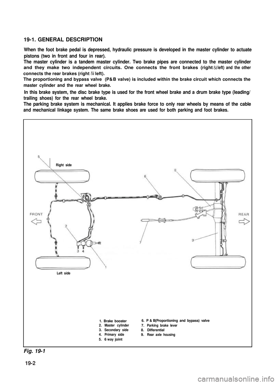
19-1. GENERAL DESCRIPTION
When the foot brake pedal is depressed, hydraulic pressure is developed in the master cylinder to actuate
pistons (two in front and four in rear).
The master cylinder is a tandem master cylinder. Two brake pipes are connected to the master cylinder
and they make two independent circuits. One connects the front brakes (right & left) and the other
connects the rear brakes (right & left).
The proportioning and bypass valve (P& B valve) is included within the brake circuit which connects the
master cylinder and the rear wheel brake.
In this brake system, the disc brake type is used for the front wheel brake and a drum brake type (leading/
trailing shoes) for the rear wheel brake.
The parking brake system is mechanical. It applies brake force to only rear wheels by means of the cable
and mechanical linkage system. The same brake shoes are used for both parking and foot brakes.
\Right side
Left side
1. Brake booster2.Master cylinder
3.Secondary side
4.Primary side
5.6 jointway
6. P & B (Proportioning and bypass) valve
7.Parking brake lever
8.Differential
9.Rear axle housing
Fig. 19-1
19-2
Page 405 of 962
Inspection for Front Brake After installing
Mount tires and make certain that they rotate
smoothly, with a force of less than 3.0 kg (6.6
lb).
NOTE:
For the above check, the following must be
observed.
1) Jack up front wheels, both right and left,
off the ground.
2) Set free wheeling hubs of both right and left
wheels to “LOCK”, if equipped.
3) Shift transfer shift lever to 2H (rear wheel)
position.
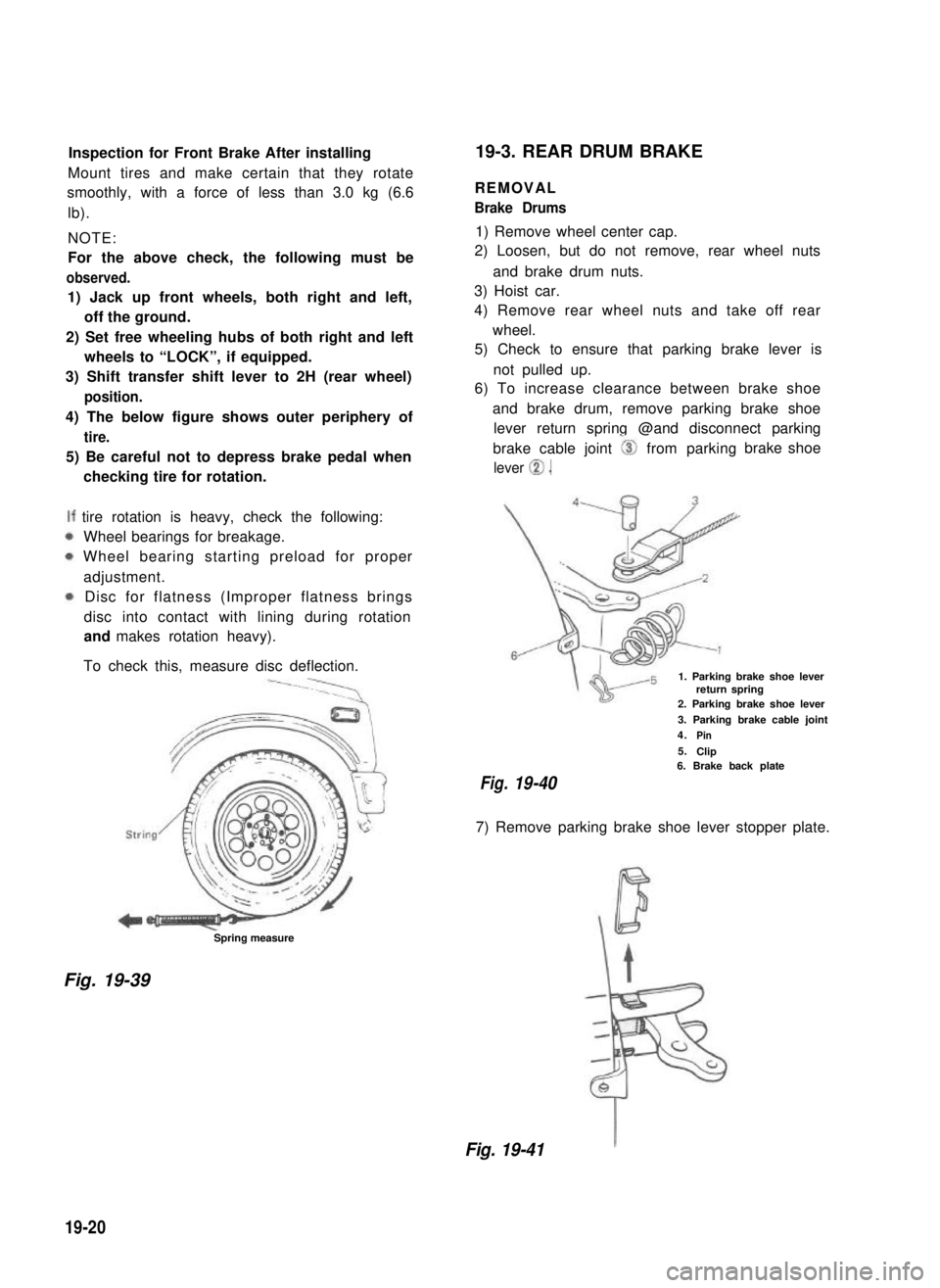
4) The below figure shows outer periphery of
tire.
5) Be careful not to depress brake pedal when
checking tire for rotation.
tire rotation is heavy, check the following:
Wheel bearings for breakage.
Wheel bearing starting preload for proper
adjustment.
Disc for flatness (Improper flatness brings
disc into contact with lining during rotation
and makes rotation heavy).
To check this, measure disc deflection.
Spring measure
19-3. REAR DRUM BRAKE
REMOVAL
Brake Drums
1) Remove wheel center cap.
2) Loosen, but do not remove, rear wheel nuts
and brake drum nuts.
3) Hoist car.
4) Remove rear wheel nuts and take off rear
wheel.
5) Check to ensure that parking brake lever is
not pulled up.
6) To increase clearance between brake shoe
and brake drum, remove parking brake shoe
lever return spring @and disconnect parking
brake cable joint 0 from parking
lever 0.
brake shoe
1. Parking brake shoe leverreturn spring2. Parking brake shoe lever
3. Parking brake cable joint
4.Pin
5.Clip6. Brake back plate
Fig.19-40
7) Remove parking brake shoe lever stopper plate.
Fig. 19-39
Fig. 19-41
19-20
Page 408 of 962
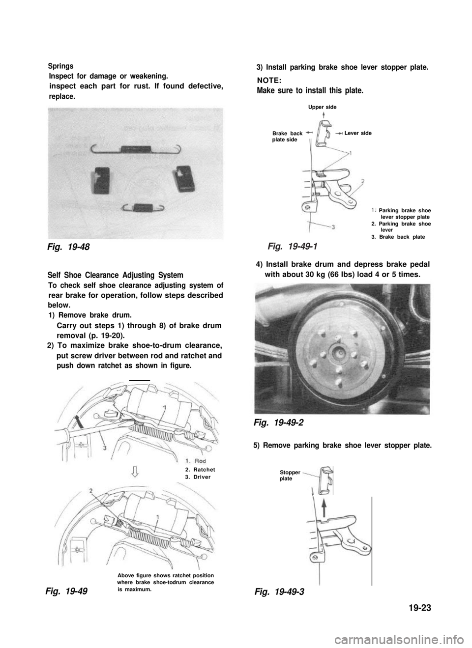
Springs
Inspect for damage or weakening.
inspect each part for rust. If found defective,
replace.
Fig. 19-48
Self Shoe Clearance Adjusting System
To check self shoe clearance adjusting system of
rear brake for operation, follow steps described
below.
1) Remove brake drum.
Carry out steps 1) through 8) of brake drum
removal (p. 19-20).
2) To maximize brake shoe-to-drum clearance,
put screw driver between rod and ratchet and
push down ratchet as shown in figure.
2. Ratchet3. Driver
Above figure shows ratchet positionwhere brake shoe-todrum clearance
3) Install parking brake shoe lever stopper plate.
NOTE:
Make sure to install this plate.
Upper side
t
Brake back -plate side
I
-W Lever side
1. Parking brake shoelever stopper plate2. Parking brake shoelever
3. Brake back plate
4) Install brake drum and depress brake pedal
with about 30 kg (66 Ibs) load 4 or 5 times.
Fig. 19-49-2
5) Remove parking brake shoe lever stopper plate.
Stopper -plate
3\
t
F
c,rG
8
Fig. 19-49is maximum.Fig. 19-49-3
19-23
Fig. 19-49-1
Page 410 of 962
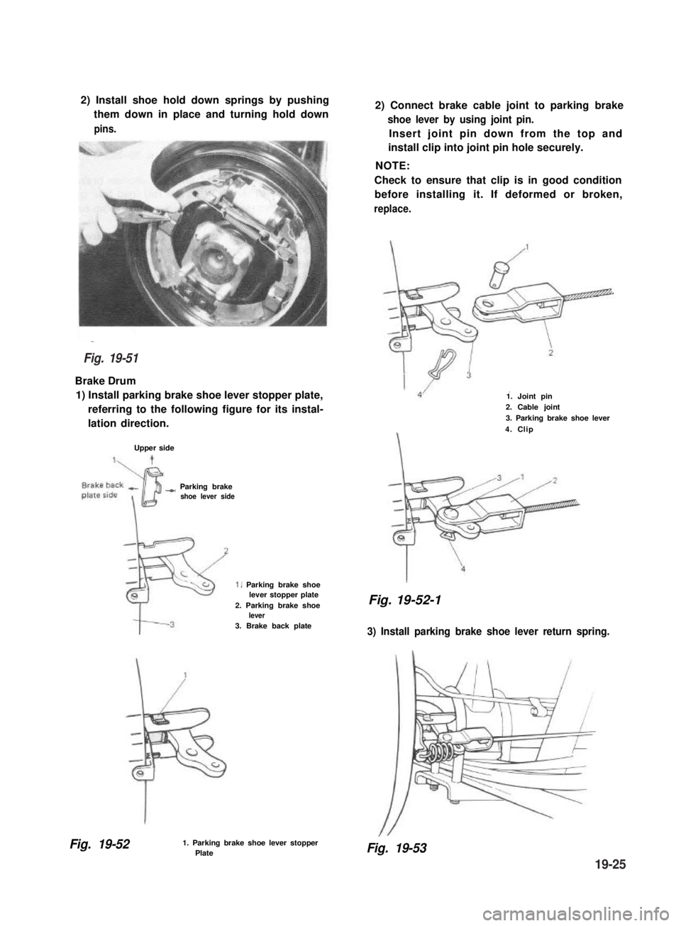
2) Install shoe hold down springs by pushing
them down in place and turning hold down
pins.
Brake Drum
1) Install parking brake shoe lever stopper plate,
referring to the following figure for its instal-
lation direction.
Upper side
-) Parking brakeshoe lever side
1. Parking brake shoelever stopper plate2. Parking brake shoelever3. Brake back plate
Fig. 19-521. Parking brake shoe lever stopperPlate
2) Connect brake cable joint to parking brake
shoe lever by using joint pin.
Insert joint pin down from the top and
install clip into joint pin hole securely.
NOTE:
Check to ensure that clip is in good condition
before installing it. If deformed or broken,
replace.
1. Joint pin2. Cable joint
3. Parking brake shoe lever
4. Clip
Fig. 19-52-1
3) Install parking brake shoe lever return spring.
Fig. 19-53
Fig. 19-51
19-25
Page 411 of 962
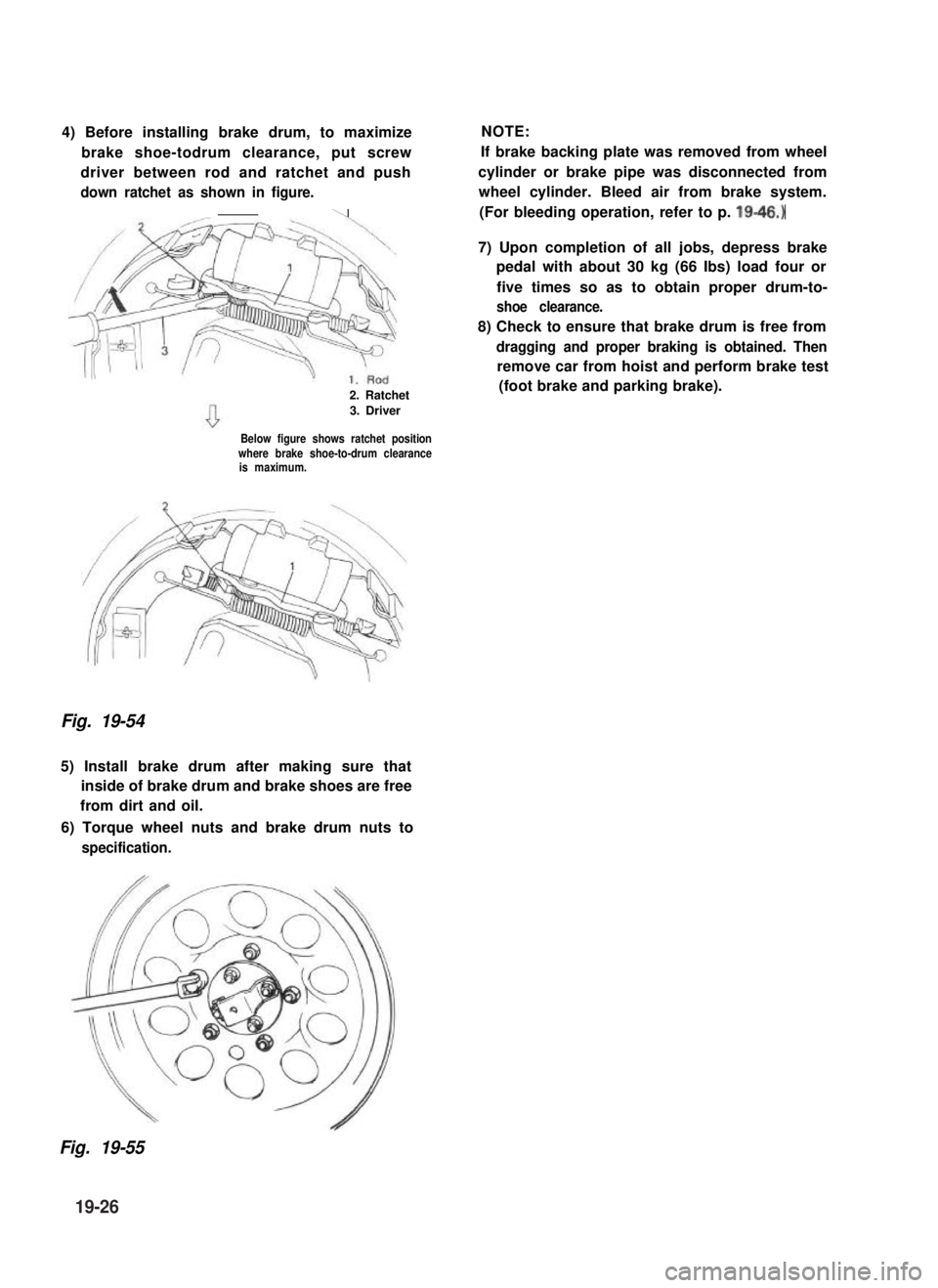
4) Before installing brake drum, to maximize
brake shoe-todrum clearance, put screw
driver between rod and ratchet and push
down ratchet as shown in figure.
\
2. Ratchet
3. Driver
Below figure shows ratchet positionwhere brake shoe-to-drum clearanceis maximum.
Fig. 19-54
5) Install brake drum after making sure that
inside of brake drum and brake shoes are free
from dirt and oil.
6) Torque wheel nuts and brake drum nuts to
specification.
NOTE:
If brake backing plate was removed from wheel
cylinder or brake pipe was disconnected from
wheel cylinder. Bleed air from brake system.
(For bleeding operation, refer to p. 19-46.)
7) Upon completion of all jobs, depress brake
pedal with about 30 kg (66 Ibs) load four or
five times so as to obtain proper drum-to-
shoe clearance.
8) Check to ensure that brake drum is free from
dragging and proper braking is obtained. Then
remove car from hoist and perform brake test
(foot brake and parking brake).
Fig. 19-55
19-26