1987 SUZUKI GRAND VITARA charging
[x] Cancel search: chargingPage 2 of 962
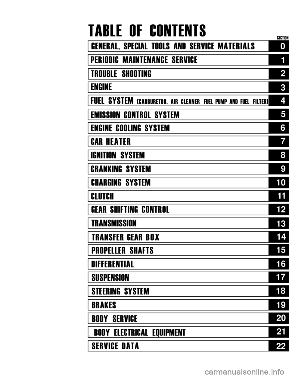
TABLE OF CONTENTS
GENERAL, SPECIAL TOOLS AND SERVICE MATERIALS
PERIODIC MAINTENANCE SERVICE
TROUBLE SHOOTING
ENGINE
FUEL SYSTEM (CARBURETOR, AIR CLEANER FUEL PUMP AND FUEL FILTER)
EMISSION CONTROL SYSTEM
ENGINE COOLING SYSTEM
CAR HEATER
IGNITION SYSTEM
CRANKING SYSTEM
CHARGING SYSTEM
CLUTCH
GEAR SHIFTING CONTROL
TRANSMISSION
TRANSFER GEAR BOX
PROPELLER SHAFTS
DIFFERENTIAL
SUSPENSION
STEERING SYSTEM
BRAKES
BODY SERVICE
,i BODY ELECTRICAL EQUIPMENT
SERVICE DATA
0
1
2
5
6
7
8
9
10
1111
12
13
14
15
16
17
18
19
20
21
22
4
3
SECTION
Page 40 of 962

2-1. ENGINE
Cond it ion
Poor starting
(Hard starting)
Possible cause
Starter will not run
1. Main fuse blown off
2. Contact not closing in main switch, or this
switch open-circuited
3. Run-down battery
4. Defective magnetic switch of starter
5. Loose battery terminal connection
6. Defective brushes in starter
7. Loose battery cord connection
8. Open in field or armature circuit of starter.
Correction
Replace
Repair or replace
Recharge
Replace
Clean and retighten
Replace
Retighten
Repair or replace
No sparking
1. Defective spark plugAdjust gap, or replace
2. High tension cord short-circuited (grounded)Repair or replace
3. Cracked rotor or cap in distributorReplace
4. Defective signal generator or ignitorReplace
5. Maladjusted signal rotor air gap.Adjust
6. Contact not closing positively in main switch,Replace
or this switch open-circuited
7. Loose or blown fuseSet right or replace
8. Improper ignition timingAdjust
9. Defective ignition coil.Replace
Faulty intake and exhaust systems
1. Carburetor out of adjustment
2. Fuel pump not discharging adequately
3. Clogged fuel filter
4. Defective choke mechanism
5. Loose intake manifold
6. Dirty and clogged carburetor
7. Float level out of adjustment
8. Clogged fuel hose or pipe
9. Not enough fuel in the tank
10. Malfunctioning fuel cut solenoid valve
Adjust
Replace
Clean, or replace
Repair or replace
Retighten
Disassemble and clean
Adjust
Clean or replace
Refill
Check solenoid valve for
proper operation and
replace if necessary
Abnormal engine internal condition
1. Ruptured cylinder head gasket
2. Improper valve clearance
3. Weakened or broken valve spring
4. Loose manifold, permitting air to be
drawn in
5. Worn pistons, rings or cylinders
Replace
Adjust
Replace
Retighten and, as neces-
sary, replace gasket
Replace worn rings and
pistons and rebore as
necessary
2-2
Page 42 of 962

ConditionPossible causeCorrection
Not enough powerEmission control
1. Malfunctioning EGR valve
Check and replace as
necessary.
Check and replace as
2. Malfunctioning bowl vent solenoid valve.necessary.
Check and replace as
3. Malfunctioning high altitude switch.necessary
Check nad replace as
4. Malfunctioning throttle position switch
(wide open switch)
necessary
Others
1. Dragging brakes
2. Slipping clutch
.Repair or replace
Adjust or replace
Engine hesitatesAbnormal condition in electrical systems
(Momentary lack of1. Defective spark plug or plug gap out ofReplace or adjust gap
response as the acceler-
ator
adjustment
is depressed. Can2. Cracked rotor or cap in distributor,Replace
occur at all car speeds.resulting in leakage
Usually most severe3. Deteriorated ignition coil, or crackReplace
when first trying toresulting in leakage
make the car move, as4. Leaky high-tension cordsReplace
from a stop sign.)5. Ignition timing out of adjustmentAdjust as prescribed
Abnormal condition in fuel system
1. Improper adjustment of float level
2. Clogged carburetor jets
3. Malfunctioning accelerator pump
Adjust
Clean
Check and replace as
necessary
4. Inadequately discharging fuel pumpReplace
Abnormal condition in engine
1. Loss of compression pressure due to leaky
cylinder head gasket
Replace
2. Compression pressure too low because ofReplace and rebore as
worn pistons, rings, cylinders or burnt valvesnecessary
Emission control
1. Malfunctioning bowl vent solenoid valveCheck and replace as
necessary
2. Malfunctioning throttle position switch
(wide open switch)
3. Malfunctionnig high altitude switch
4. Malfunctioning EGR valve
Check and replace as
necessary
Check and replace as
necessary
Check and replace as
necessary
5. Malfunctioning thermostatically controlled
air cleaner
Check and replace as
necessary
2-4
Page 55 of 962
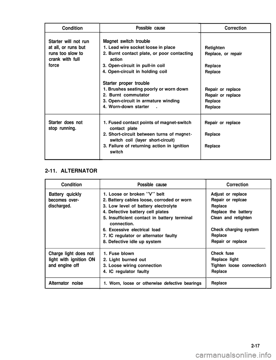
Condition
Starter will not run
at all, or runs but
runs too slow to
crank with full
force
Starter does not
stop running.
2-11. ALTERNATOR
Condition
Battery quickly
becomes over-
discharged.
Charge light does not
light with ignition ON
and engine off
Alternator noise
Possible cause
Magnet switch trouble
1. Lead wire socket loose in place
2. Burnt contact plate, or poor contacting
action
3. Open-circuit in pull-in coil
4. Open-circuit in holding coil
Starter proper trouble
1. Brushes seating poorly or worn down
2. Burnt commutator
3. Open-circuit in armature winding
4. Worn-down starter.
1. Fused contact points of magnet-switch
contact plate
2. Short-circuit between turns of magnet-
switch coil (layer short-circuit)
3. Failure of returning action in ignition
switch
Possible cause
1. Loose or broken “V” belt
2. Battery cables loose, corroded or worn
3. Low level of battery electrolyte
4. Defective battery cell plates
5. Insufficient contact in battery terminal
connection.
6. Excessive electrical load
7. IC regulator or alternator faulty
8. Defective idle up system
1. Fuse blown
2. Light burned out
3. Loose wiring connection
4. IC regulator faulty
1. Worn, loose or otherwise defective bearings
Correction
Retighten
Replace, or repair
Replace
Replace
Repair or replace
Repair or replace
Replace
Replace
Repair or replace
Replace
Replace
Correction
Adjust or replace
Repair or replcae
Replace
Replace the battery
Clean and retighten
Check charging system
Replace
Repair or replace
Check fuse
Replace light
Tighten loose connection!
Replace
i
Replace
2-17
Page 234 of 962
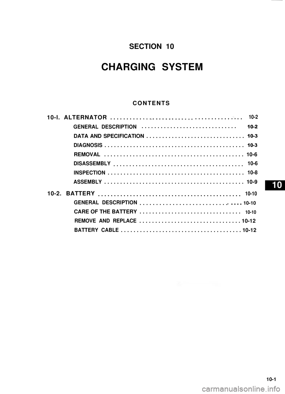
SECTION 10
CHARGING SYSTEM
CONTENTS
10-l. ALTERNATOR. . . . . . . . . . ..L.............. . . . . . . . . . . .:. . .
GENERAL DESCRIPTION10-2
DATA AND SPECIFICATION...............................10-3
DIAGNOSIS............................................10-3
REMOVAL............................................ 10-6
DISASSEMBLY.........................................10-6
INSPECTION...........................................10-8
ASSEMBLY............................................ 10-9
10-2. BATTERY.............................................10-10
GENERAL DESCRIPTION................................ 10-10
CARE OF THE BATTERY................................10-10
REMOVE AND REPLACE................................ 10-12
BATTERY CABLE...................................... 10-12
..............................
10-2
10
10-1
Page 235 of 962
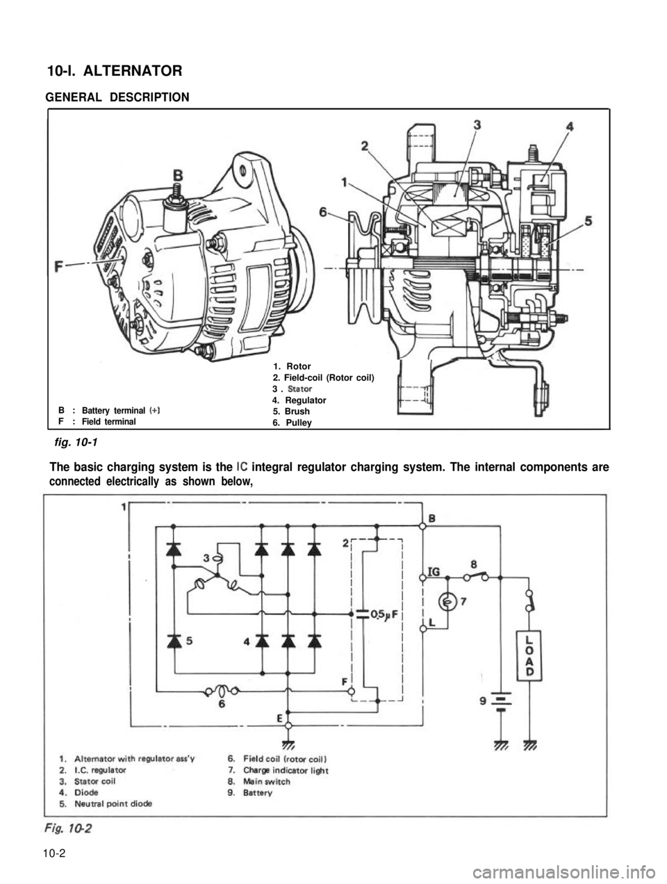
10-l. ALTERNATOR
GENERAL DESCRIPTION
B :F :Battery terminal (+)
-1. Rotor
2. Field-coil (Rotor coil)
3. Stator
4. Regulator5. BrushField terminal6. Pulley
The basic charging system is the IC integral regulator charging system. The internal components are
connected electrically as shown below,
ThTh*
1. Alternator with regulator ass’y6. Field coil (rotor coil)
2.IX. regulator7.Charge indicatorlight
3.Stator coil8.Mein switch
4.Diode9.Battery5. Neutral point diode
fig. 10-1
10-2
Page 236 of 962
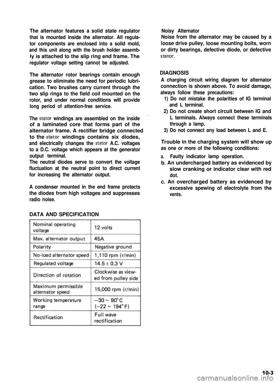
The alternator features a solid state regulator
that is mounted inside the alternator. All regula-
tor components are enclosed into a solid mold,
and this unit along with the brush holder assemb-
ly is attached to the slip ring end frame. The
regulator voltage setting cannot be adjusted.
The alternator rotor bearings contain enough
grease to eliminate the need for periodic lubri-
cation. Two brushes carry current through the
two slip rings to the field coil mounted on the
rotor, and under normal conditions will provide
long period of attention-free service.
The stator windings are assembled on the inside
of a laminated core that forms part of the
alternator frame. A rectifier bridge connected
to the stator windings contains six diodes,
and electrically changes the stator A.C. voltages
to a D.C. voltage which appears at the generator
output terminal.
The neutral diodes serve to convert the voltage
fluctuation at the neutral point to direct current
for increasing the alternator output.
A condenser mounted in the end frame protects
the diodes from high voltages and suppresses
radio noise.
DATA AND SPECIFICATION
Nominal operating
voltaga
Max. alternator output
12 volts
45A
No-load alternator speed
IDirection of rotationClockwise as view-
ed from oullev side
Maximum permissible
alternator speed
Working temperature
range
Rectification
15,000 rpm (r/min)
-3o- 90°C
(-22 - 194” F)
Full wave
rectification
Noisy Alternator
Noise from the alternator may be caused by a
loose drive pulley, loose mounting bolts, worn
or dirty bearings, defective diode, or defective
stator.
DIAGNOSIS
A charging circuit wiring diagram for alternator
connection is shown above. To avoid damage,
always follow these precautions:
1) Do not mistake the polarities of IG terminal
and L terminal.
2) Do not create short circuit between IG and
L terminals. Always connect these terminals
through a lamp.
3) Do not connect any load between L and E.
Trouble in the charging system will show up
as one or more of the following conditions:
a.Faulty indicator lamp operation.
b. An undercharged battery as evidenced by
slow cranking or indicator clear with red
dot.
c. An overcharged battery as evidenced by
excessive spewing of electrolyte from the
vents.
10-3
Page 237 of 962
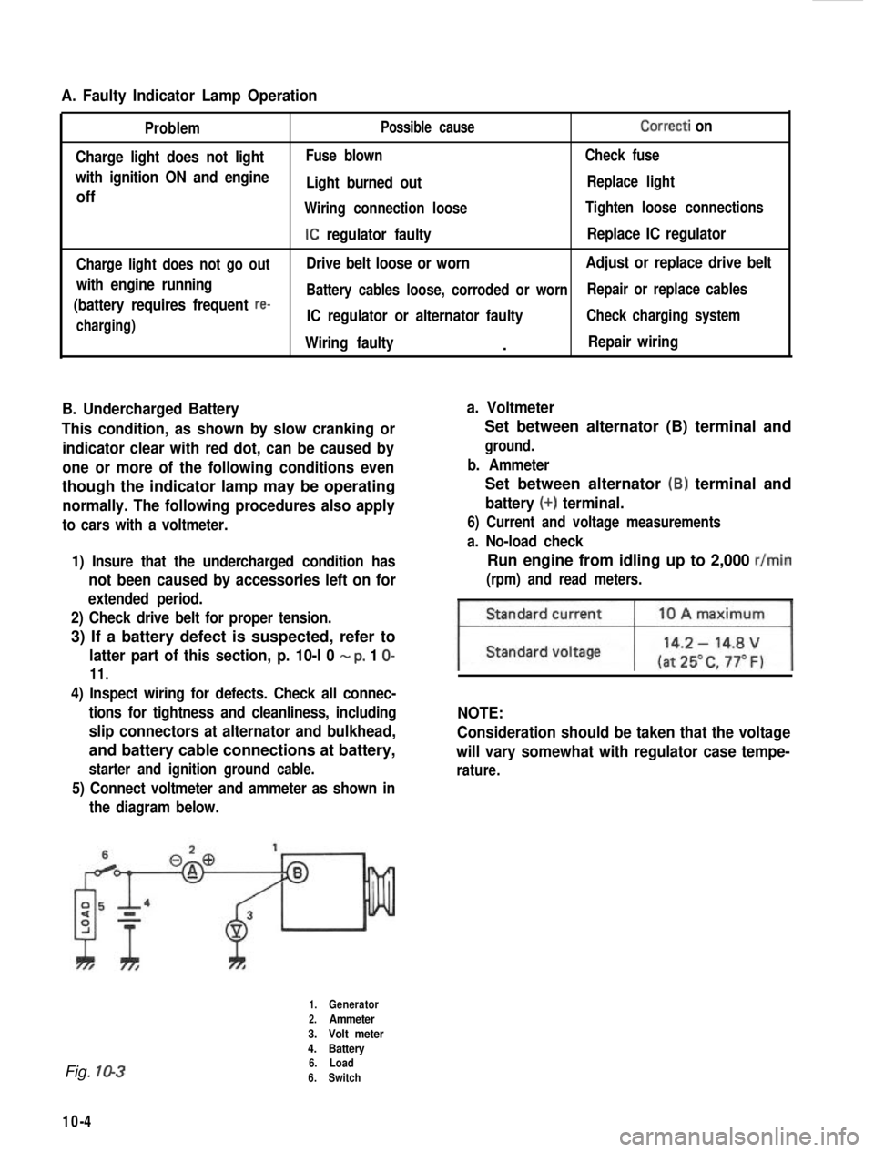
A. Faulty Indicator Lamp Operation
Problem
Charge light does not light
with ignition ON and engine
off
Charge light does not go out
with engine running
(battery requires frequent
re-
charging) Possible cause
Correcti on
Fuse blown
Check fuse
Light burned outReplace light
Wiring connection loose Tighten loose connections
IC regulator faultyReplace IC regulator
Drive belt loose or worn Adjust or replace drive belt
Battery cables loose, corroded or worn Repair or replace cables
IC regulator or alternator faultyCheck charging system
Wiring faulty.Repair wiring
B. Undercharged Battery a. Voltmeter
This condition, as shown by slow cranking or indicator clear with red dot, can be caused by
one or more of the following conditions even
though the indicator lamp may be operating
normally. The following procedures also apply
to cars with a voltmeter.
1) Insure that the undercharged condition has
not been caused by accessories left on for
extended period.
2) Check drive belt for proper tension.
3) If a battery defect is suspected, refer to
latter part of this section, p. 10-l 0 - p, 1 O-
11.
4) Inspect wiring for defects. Check all connec- tions for tightness and cleanliness, including
slip connectors at alternator and bulkhead,
and battery cable connections at battery,
starter and ignition ground cable.
5) Connect voltmeter and ammeter as shown inthe diagram below.
Set between alternator (B) terminal and
ground.
b. Ammeter
Set between alternator (B) terminal and
battery (+) terminal.
6) Current and voltage measurements
a. No-load check
Run engine from idling up to 2,000 r/min
(rpm) and read meters.
NOTE:
Consideration should be taken that the voltage
will vary somewhat with regulator case tempe-
rature.
Fig. 10-3
10-4
1.Generator
2.Ammeter
3. Volt meter
4. Battery
6. Load
6. Switch